
Industrial Controller
All product are in stock,guaranteed delivery within 3-7 days.


PRODUCT
PICTURE
BRAND
DESCRIBE
STOCK
DOWNLOAD
Technical Parameters Parameter / Feature Specification / Detail Series / Model RT7B, Part No. 2TLA010028R1000 Supply Voltage (Coil) 24 V DC Contact Configuration (Safety Outputs) 4 safety outputs: 2× NO (instantaneous) + 2× NO (delayed) + 1 NC auxiliary contact (i.e. 2NO/2NO/1NC) Delayed Output Timings Delay selectable: 0 s, 1 s, 2 s, or 3 s (for soft-stop function) Input Configuration Single‑channel or dual‑channel inputs supported (for redundant safety wiring) Additional Outputs 3 voltage‑free transistor “information” outputs (status signalling of inputs/outputs/delay) Reset Modes Manual supervised reset or automatic reset (configurable per installation) Contact Material & Protection Contact material: AgSnO₂ with Au flash; support for external fuses: outputs 1/2: 5 A gL/gG, outputs 3/4: 3 A gL/gG; suitable for safe switching of loads. Power Consumption ~ 4.6 W (at 24 V DC supply) Mounting & Connections Mounts on standard 35 mm DIN‑rail; screw / plug‑in terminal blocks; quick‑release connector blocks supported Enclosure / Protection Rating Housing: IP40; Terminals / connection blocks: IP20 Operating Temperature –10 °C to +55 °C Standards / Safety Category Safety Category up to Cat. 4 (with correct wiring), compliant with relevant safety standards (e.g. EN 62061, EN ISO 13849‑1) Mechanical / Electrical Endurance Long lifetime, designed for many switching cycles (suitable for safety‑critical applications) Dimensions Approx. 84 mm height × 45 mm width × 120 mm depth Typical Applications Guard‑door / gate interlocks, emergency stop circuits, light‑curtain / beam safety, safety mats/edges, enabling‑device monitoring, machine output contactor safety control, safety output expansion, “soft‑stop” on safety event, general machine safety circuits.
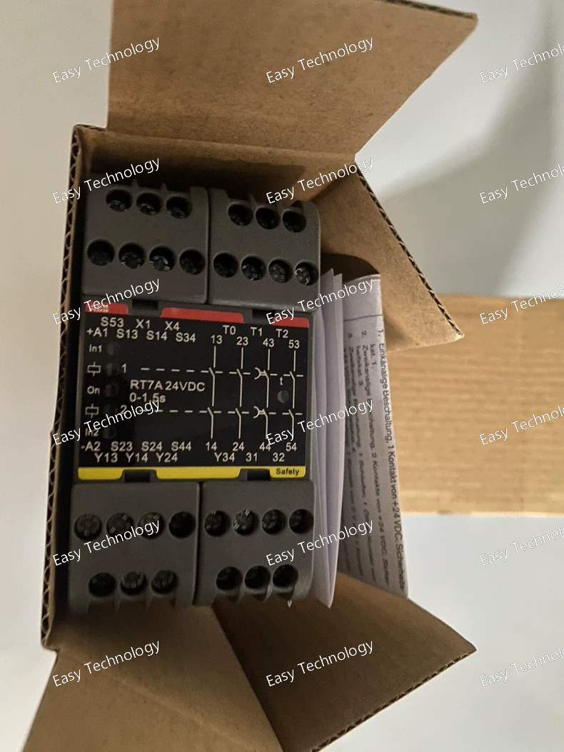
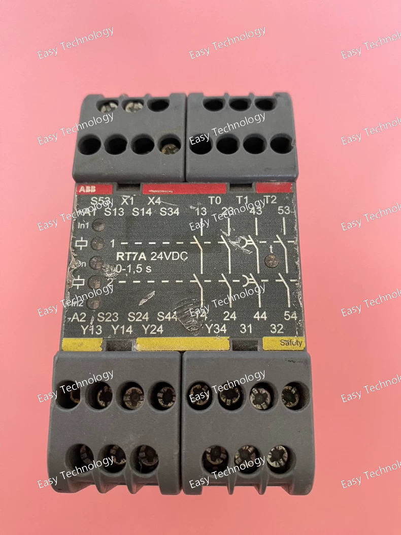
Technical Parameters Parameter / Feature Specification / Detail Product / Series RT7A safety relay — 2TLA010028R2000 Supply Voltage (Coil) 24 V DC Output Contacts (Safety Outputs) 2 × NO (normally open) + 2 × NO (second set, or delayed) + 1 × NC (normally closed) — often described as 2NO/2NO/1NC output form Delayed Outputs Two outputs have a delay function (1.5 s nominal) for controlled safety stop Input Channels Single‑ or dual‑channel input configuration (for redundancy / safety wiring) Reset Mode Automatic reset or manual supervised reset selectable Auxiliary / Information Outputs 1 NC “information” output + up to 3 potential‑free transistor information outputs (for status signaling, not safety outputs) Mounting / Terminals 35 mm DIN‑rail mounting; screw‑clamp terminal blocks / quick release terminal blocks Enclosure / Protection Rating Enclosure: IP40; Terminals: IP20 Dimensions (W × H × D) 45 mm × 84 mm × 120 mm Power Consumption / Supply ~ 4.6 W (with 24 V DC supply) Safety Category / Performance Level Safety Category 4 (when correctly wired), suitable for safety‑relevant applications (guard interlocks, emergency stop, light‑curtains etc.) Typical Applications Safety‑interlocks, emergency‑stop circuits, light‑curtain or light‑beam monitoring, safety gate/door guards, enabling devices, safety‑mat / edge detection, output expansions with safety functionality, delayed output stop, machine safety circuits
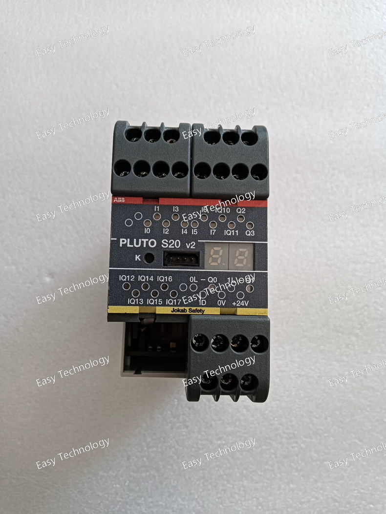
Technical Parameters Parameter / Feature Specification / Detail Product / Model Pluto S20 v2 Safety PLC — 2TLA020070R4700 Supply Voltage (Us) 24 V DC Total I/O Count 20 I/O (mixed) Failsafe Inputs 8 inputs Configurable Outputs / Inputs (safe / non‑safe) 8 channels (can be non‑failsafe outputs or failsafe‑inputs) Failsafe Outputs 4 total — consisting of 2 relay outputs + 2 transistor outputs Safety Outputs 2 failsafe relay outputs (potential‑free), 2 failsafe transistor outputs Non‑safety Outputs Up to 8 channels (if configured as non‑safe outputs / safe inputs) Safety Category / Performance Level / Safety Integrity Up to Performance Level (PL) e; complies with highest safety standards (SIL 3 / Cat. 4 level in safety systems) Diagnostic Coverage High (for safety‑critical applications) Protocol / Communication Supports internal protocols (e.g. StatusBus / MODBUS‑ASCII) for system integration / communication between modules Mounting / Enclosure / Protection DIN‑rail mounting; Enclosure protection IP40, Terminals protection IP20 Dimensions (W × H × D) 45 mm × 84 mm × 120 mm Net Weight ~ 0.39 kg Typical Use Cases / Applications Machine safety control, safety‑circuit logic, emergency stop handling, interlocking guards/doors, multi‑sensor safety interlocks, modular safety systems, general industrial automation safety
Technical Parameters Parameter / Feature Specification / Detail Product / Series Pluto B20 v2 Safety PLC — model 2TLA020070R4600 Supply Voltage (Control / Power) 24 V DC I/O Configuration 20 I/O total: 8 failsafe inputs + 8 non-failsafe outputs/failsafe‑inputs + 2 individually failsafe relay outputs + 2 individually failsafe transistor outputs Safe Outputs 2 failsafe relay outputs (NO/NC type) + 2 failsafe transistor outputs Other Outputs / Non‑safety Outputs 8 non-failsafe outputs / failsafe‑inputs (configurable I/O) Safety Performance Level Up to PL e (Performance Level e) — suitable for highest category safety applications (Cat. 4 SIL 3) Diagnostic Coverage High diagnostic coverage Communication / Bus (if used) Pluto Safety Bus (for connecting multiple Pluto units/modules) Mounting / Mechanical DIN‑rail mounting (standard 35 mm rail) Enclosure / Protection Rating Enclosure: IP40; Terminals: IP20 (per datasheet) Dimensions (W × H × D) 45 mm × 84 mm × 120 mm Weight (net) ~ 0.39 kg Operating Temperature Range −10 °C to +55 °C (per module spec) Typical Applications Machine safety control, safety‑circuit logic, emergency‑stop handling, multi‑sensor safety interlock systems, safety bus networks, modular safety systems for industrial automation
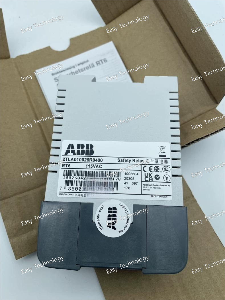
Technical Parameters Parameter / Feature Specification / Detail Series / Model RT6 Safety Relay — 115 AC version (2TLA010026R0400) Supply (Coil) Voltage 115 V AC (A1–A2) Input Channels 1 or 2 (single- or dual‑channel configuration) Safety Inputs Supported Emergency stop, safety mats/edges, light curtains/beams, safety switches / interlocks, gates/doors, enabling devices, contact strips, etc. Reset Modes Manual supervised reset or Automatic reset (configurable) Safety Output Contacts 3 × NO (normally open) + 1 × NC (normally closed) — total 4 safety‑rated contacts Contact Rating / Switching Capacity (Resistive Load) 6 A @ up to 250 V AC (resistive) / up to 1500 VA maximum Inductive Load Capacity e.g. AC‑15: 2 A @ 240 V AC; DC‑13: 1 A @ 24 V DC (when used on DC) Maximum Total Switching Capacity 12 A distributed across all outputs Minimum Load Capacity 10 mA @ 10 V (if contact load does not exceed 100 mA) Auxiliary / Information Outputs Two voltage‑free transistor “info” outputs (Y14, Y24) — for status signalling (not to be used as safety outputs) Auxiliary Output Supply / Load External +5 V … +30 V DC supply; max 15 mA per output; max voltage drop ~2.4 V at full load Mounting / Terminals 35 mm DIN‑rail mounting; plug‑in / screw‑clamp terminal blocks Enclosure / Protection Housing: IP40; Terminals: IP20 Product Dimensions Width: ~45 mm; Height: ~84 mm; Depth: ~120 mm Weight (net) ~ 0.485 kg Mechanical Endurance > 10⁷ operations (long lifetime) Safety Category / Standard Compliance Safety Category 4 / Performance Level e (when properly wired, dual‑channel, with monitoring) — compliant with safety‑relay standards for machine safety
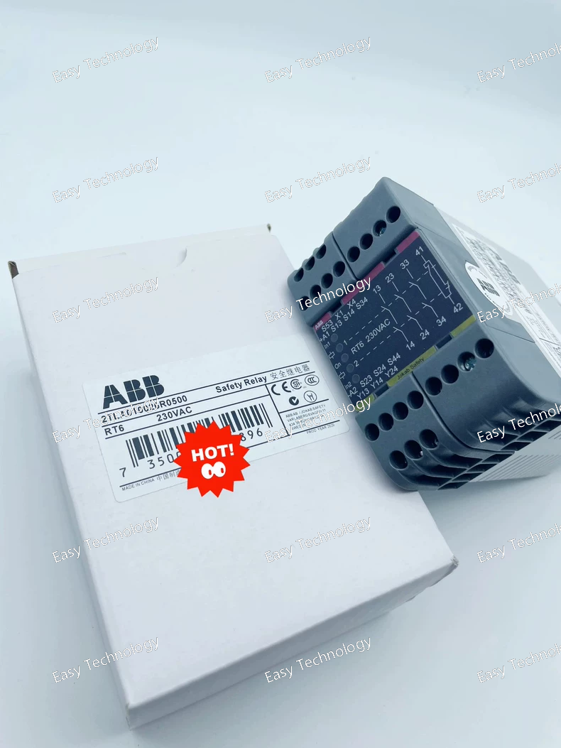
Technical Parameters Parameter / Feature Specification / Detail Product / Series RT6 230 AC Safety Relay (Part No. 2TLA010026R0500) Control Supply Voltage (Coil) 230 V AC Input Modes Single‑channel or dual‑channel safety inputs; supports various safety devices (E‑stop, mats/edges, light curtains, interlocks, enabling devices, etc.) Reset Mode Manual supervised reset or automatic reset (configurable) Output Contacts (Safety Outputs) 3 × Normally‑Open (NO) contacts + 1 × Normally‑Closed (NC) contact (3NO + 1NC) Contact Current Rating 6 A Contact Voltage (AC) Up to 250 V AC (nominal) Relay Mounting / Enclosure DIN‑rail mounting; screw‑terminal connections; enclosure protection IP40 (housing), terminals rated IP20 Mechanical / Electrical Life High durability (typical for RT6 series, long operational life) Auxiliary / Information Outputs Two voltage‑free transistor “information” outputs (for status indication) Housing / Dimensions Width ~ 45 mm; Depth ~ 120 mm; Height ~ 84 mm; net weight ~ 0.485 kg Standards / Safety Performance Safety Category 4, Performance Level e (PL e), SIL 3 (for safety‑related applications) Typical Applications Emergency stop circuits; safety mats/edges; light curtains/beams; interlocked gates/doors; enabling devices; guard/door monitoring; general safety‑circuit supervision and output expansion
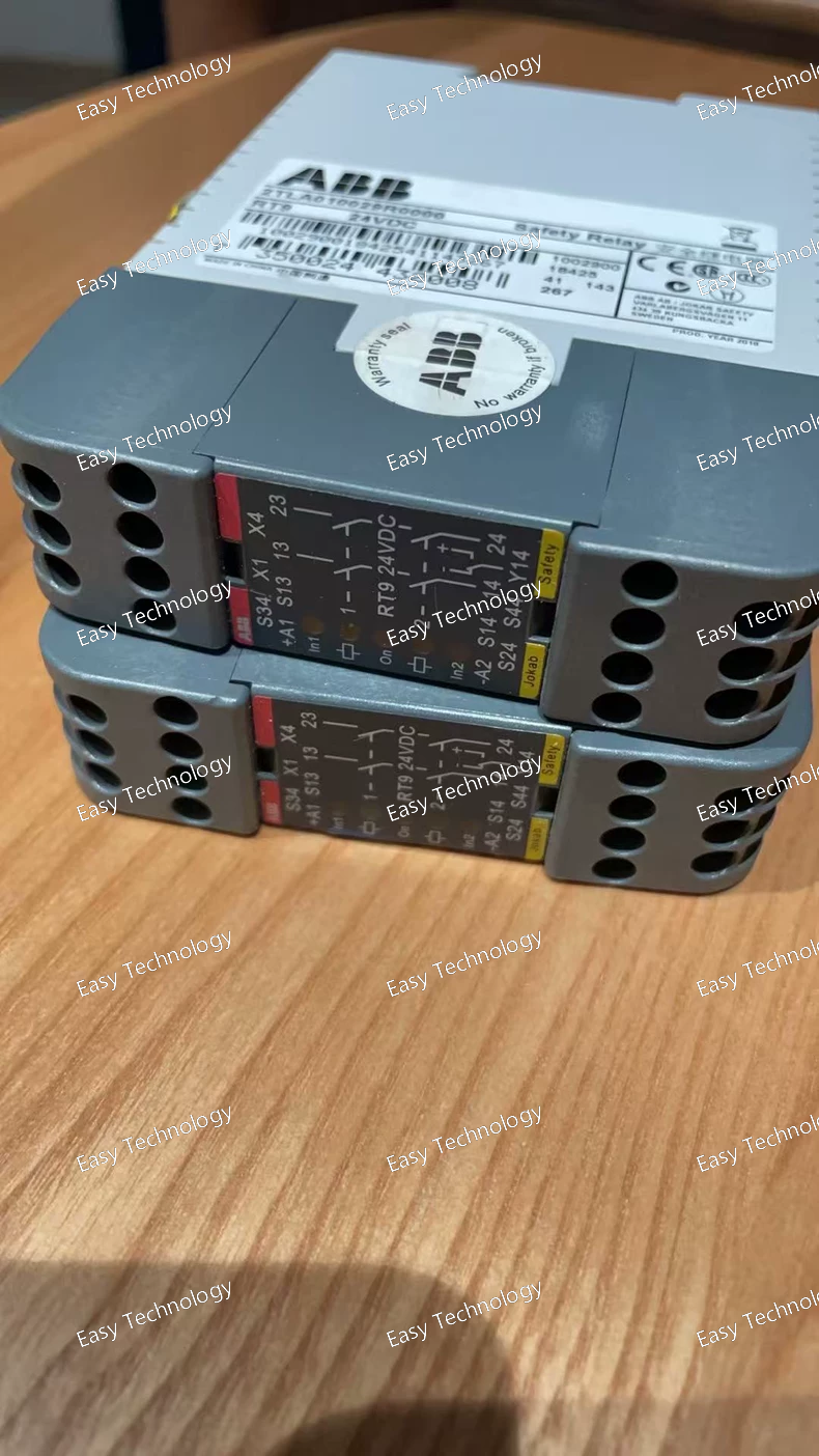
Technical Parameters Parameter / Feature Specification / Detail Part Number / Series 2TLA010029R0000 — RT9 24 VDC Safety Relay Control Supply Voltage (Us) 24 V DC Accepted Input Types Single‑channel or dual‑channel inputs (supports e.g. OSSD, safety mats, emergency stop, safety switches, interlocks, light curtains, enabling devices, foot controls, contact strips, etc.) Reset Modes Manual supervised reset or automatic reset selectable Supervision / Reset Input Test/reset input to verify external contactor/valve drop before reset Output Contacts (Safety Outputs) 2 × NO (two “safety” outputs) Contact Rating / Switching Capacity 6 A @ 250 V AC (resistive), or 6 A @ 24 V DC (resistive); total switching capacity distributed across contacts; minimum load ~ 10 mA @ 10 V Contact Material Silver + Au‑flash (Ag + Au flash) Information Output One information (auxiliary) output (for system status signalling) Mounting / Connection 35 mm DIN‑rail mounting; screw‑clamp terminals / terminal‑block connection Enclosure / Terminal Protection / IP Rating Enclosure IP40; terminals IP20 Dimensions (W × H × D) 22.5 mm × 84 mm × 120 mm Mechanical / Electrical Life Mechanical life > 10⁷ operations; dielectric / impulse withstand (for safe isolation) Safety Category / Performance Level Up to Category 4 / Performance Level e (per safety standards) — suitable for safety‑relevant applications Typical Applications Emergency‑stop circuits, safety‑interlocks (guards/doors), safety mats/edges, light curtains/beams, enabling devices, safety‑switches, gate/hatch interlocking, safety output expansion, general machine safety circuits
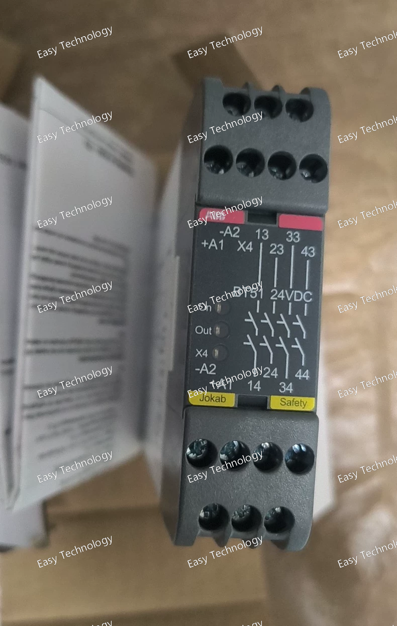
Technical Parameters Parameter / Feature Specification / Detail Supply Voltage (coil / control) 24 V DC Relay Type / Series BT51 24 VDC Safety / Expansion Relay Output Contacts 4 × Normally‑Open (4 NO) safety contacts Contact Rating / Switching Capacity (Resistive Load) 6 A @ 250 V AC (max 1500 VA), or 6 A @ 24 V DC (max 150 W) Inductive Load Capacity 2 A @ 240 V AC (AC‑15), 1 A @ 24 V DC (DC‑13) Maximum Total Switching Capacity (all contacts) 12 A (distributed among contacts) Minimum Load Capacity 10 mA @ 10 V (when contact load ≤ 100 mA) Reset / Supervision Features Internal supervision; test/reset input to ensure contactors/valves have dropped before restart Input‑Output Isolation / Safety Category Safety Category: Cat. 4 / Performance Level (PL): e (per ISO 13849‑1) / SIL 3 (per IEC 61508) Terminals / Connection Screw‑type terminals, DIN‑rail mounting (35 mm rail) Enclosure / Protection Rating IP40 (housing); terminals rated IP20 Operating Temperature –10 °C … +55 °C Dimensions (W × D × H) 22.5 mm × 120 mm × 84 mm Power Consumption Approx. 1.4 … 1.8 W Contact Material Silver with gold flash (Ag + Au flash)
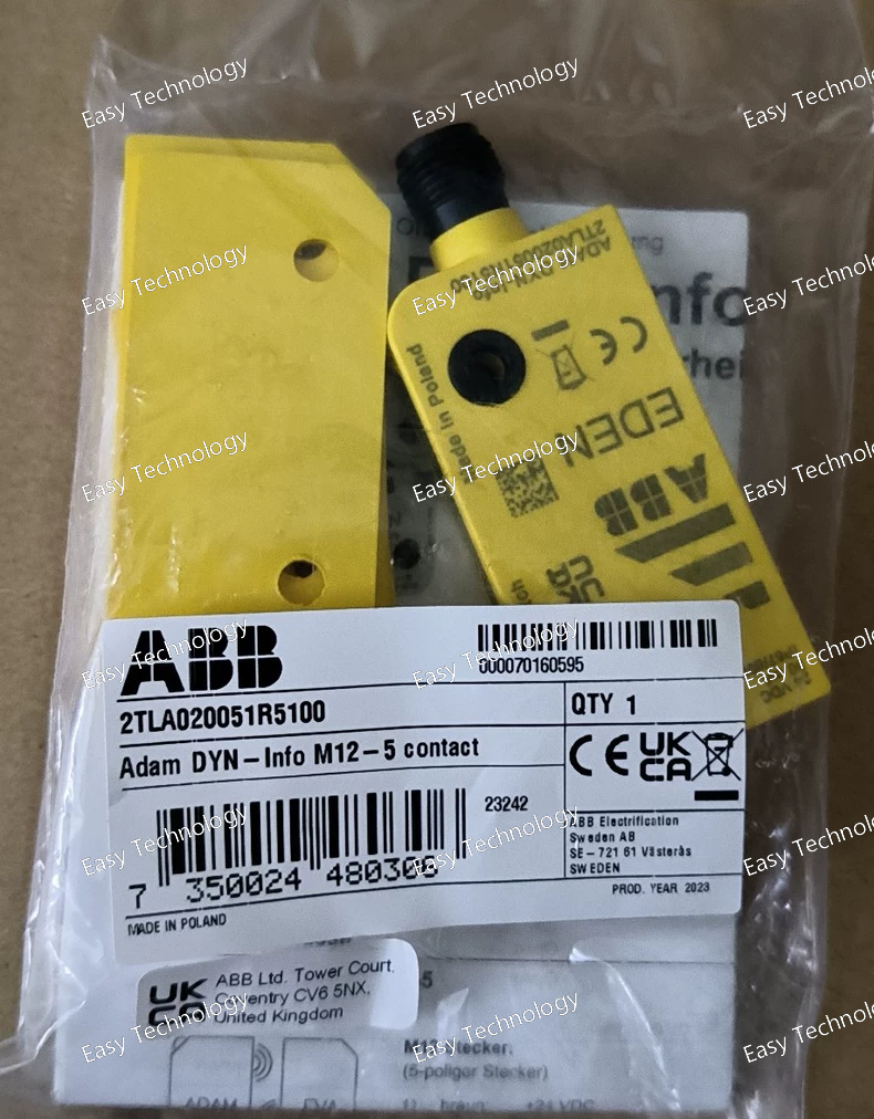
Technical Parameters Parameter / Feature Specification / Detail Part Number 2TLA020051R5100 Series / Type Eden — Adam DYN‑Info M12‑5 Function Non‑contact safety sensor (interlock / position monitoring) Supply Voltage 24 V DC Output Type DYNlink signal + information output (non-failsafe “info” output) Number of Outputs 1 information output (semiconductor) — no safety‑rated contacts in this variant Sensing / Switching Principle Magnetic / reed (non‑contact detection) Maximum Sensing / Operating Distance 15 mm Connection Type M12‑5 male connector (fixed 5‑pole) Enclosure / Protection IP67, IP69K (suitable for dust, water, wash‑down conditions) Material Plastic housing (often PBT) Dimensions Width ~ 30 mm, Depth ~ 12 mm, Height ~ 75.2 mm Weight (net) ~ 0.026 kg Operating Temperature Range –40 °C … +70 °C Certifications / Safety Level Can be used in safety‑relevant applications (Eden safety sensor series) — often used to reach high safety performance levels when combined with appropriate safety controller; UL/CSA/CE compliance typical Mounting / Installation 360° mounting allowed, actuator (Eva) must be ordered separately
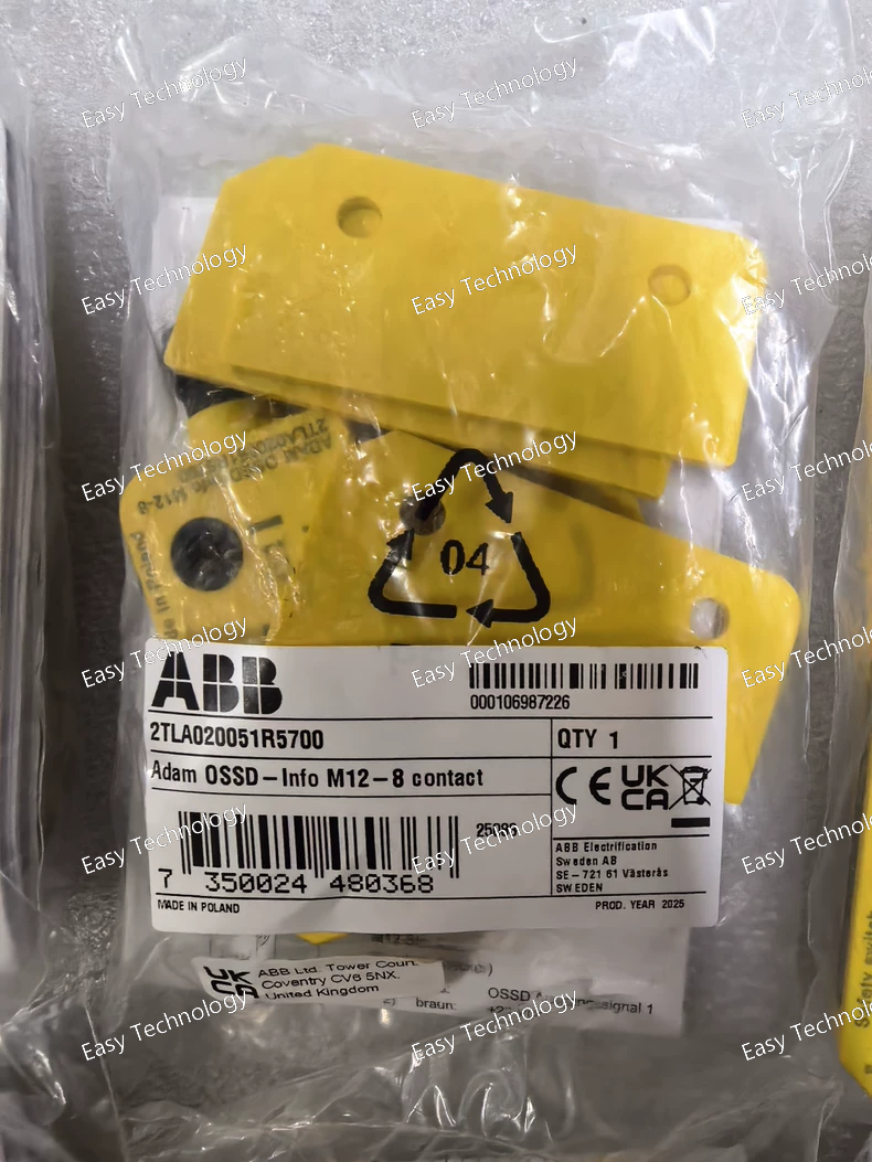
Technical Parameters Parameter / Feature Specification / Detail Product Non‑contact safety sensor — Adam OSSD‑Info M12‑8 (Eden series) Part Number 2TLA020051R5700 Interface / Connector M12‑8 male connector Supply Voltage 24 V DC Output Type OSSD output + information output (non‑failsafe semiconductor output) Sensing Principle Magnetic / reed non‑contact detection (requires matching actuator “Eva”) Sensing / Switching Distance Up to 15 mm Supply Current ~ 30 mA Protection / Enclosure Rating IP67 and IP69K (suitable for wet/harsh conditions) Operating Temperature Range –40 °C to +70 °C Housing Material Plastic (polybutylene terephthalate, PBT) Dimensions (approx.) Height 75.2 mm × Width 30 mm × Depth 12 mm Mounting / Mounting Flexibility 360° mounting possibility (versatile installation orientation) Application / Use Case Safety interlocking, guard/door monitoring, safe‑position detection, OSSD‑based safety circuits
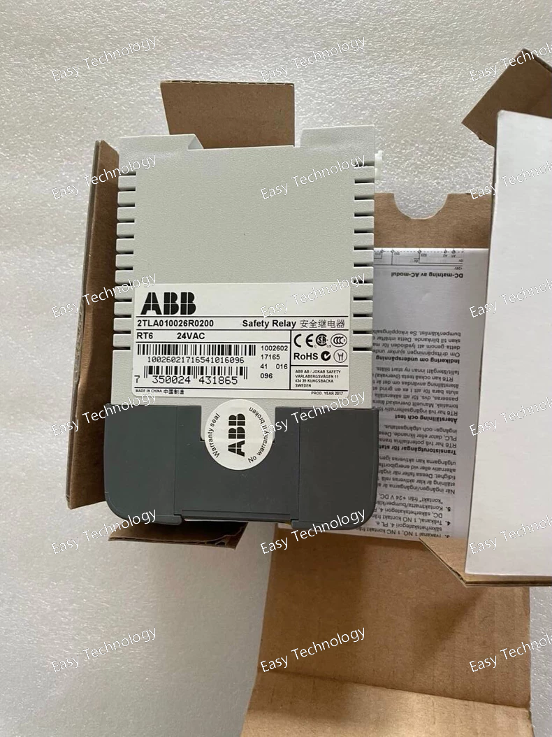
Technical Parameters Parameter / Feature Specification Control (Coil) Supply Voltage (A1–A2) 24 VAC Product Type / Series RT6 safety relay Safety Contact Outputs 3 × NO + 1 × NC safety‑rated contacts (safety outputs) Contact Current Rating 6 A @ 250 VAC (resistive) Max Switching Capacity (Resistive) 1500 VA (AC) Inductive Load Capacity AC‑15: 2 A @ 240 VAC DC Load Capacity 6 A @ 24 VDC (resistive) / 1 A @ 24 VDC (inductive) Minimum Load 10 mA @ 10 V (when load on contact ≤ 100 mA) Total Max Switching Capacity 12 A (distributed across all contacts) Mechanical Lifespan > 10^7 operations (high durability) Mounting 35 mm DIN‑rail Housing / Protection Enclosure: IP40; Connection terminals: IP20 Reset Modes Manual or Automatic reset supported Information / Transistor Outputs Two short‑circuit‑protected auxiliary outputs (for status signals), external supply +5 to +30 VDC — typical load 15 mA / output Indicators LED status indication (supply OK, input and output status) Safety Standards / Category Safety category 4 (according to EN/ISO safety standards) — suitable for safety‑relevant applications (e.g. mats, interlocks, safety light curtains) Application Examples Safety mats/edges, safety light curtains/beams, emergency stop circuits, safety interlocks, access gates/guards/doors monitoring
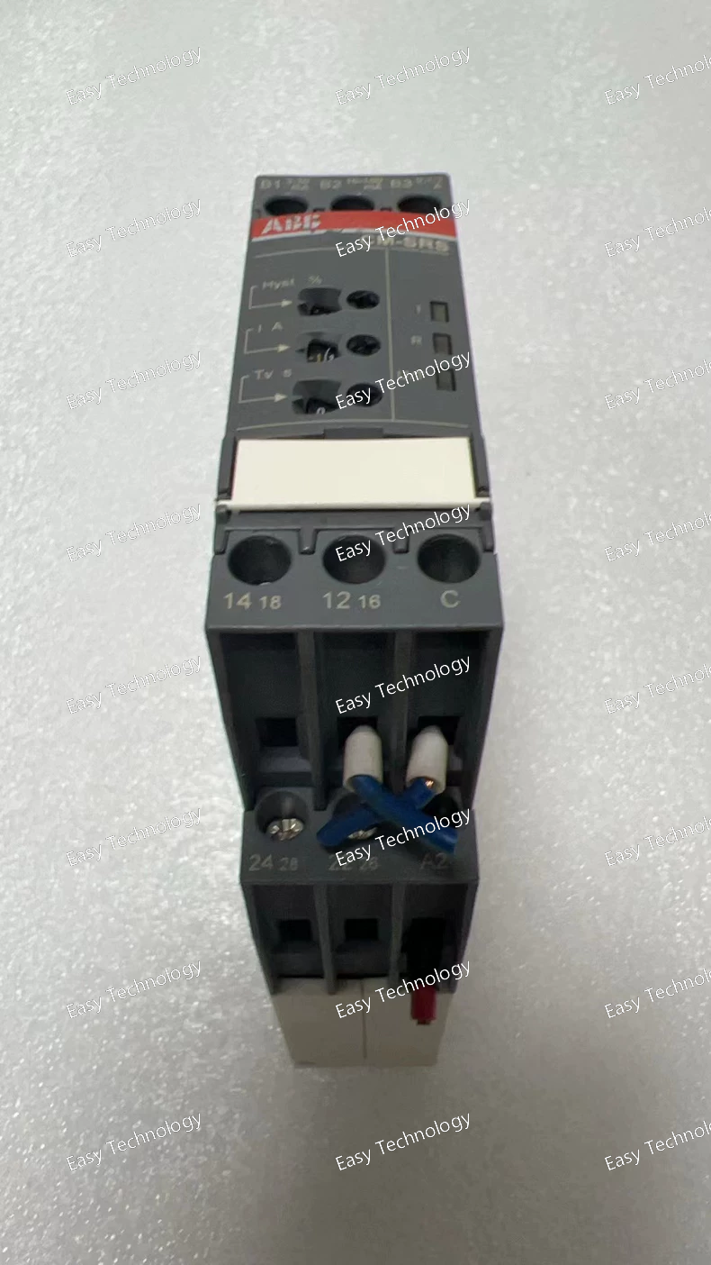
Technical Parameters Parameter / Feature Specification Supply (Control) Voltage 220–240 V AC Measured Current Ranges (RMS) 3–30 mA, 10–100 mA, 0.1–1 A Functionality Over‑current monitoring and under‑current monitoring (configurable) Output Contacts 2 × changeover contacts (SPDT / 2 c/o) Contact Rating 250 V AC / 4 A (resistive load) Tripping Delay / Time Setting Instantaneous (0 s) or adjustable delay 0.1–30 s (ON) Hysteresis (Threshold Dead‑band) Adjustable: 3%–30% of threshold level Connection / Terminals Screw‑type terminals (double‑chamber/cage connection) Mounting DIN‑rail (TH35 per IEC 60715) Dimensions (W × H × D) 22.5 mm × 85.6 mm × 103.7 mm Operating Ambient Temperature –20 °C … +60 °C Storage Temperature –40 °C … +85 °C Insulation / Overvoltage / Protection Rated insulation voltage between measuring and output circuits; output circuit max 300 V; housing IP50 / terminals IP20; pollution degree 3, overvoltage category III Application Single‑phase current monitoring (AC or DC), over‑/under‑current protection in control panels, machinery or industrial installations
 TEL: Grace +86 13600179521
  Mail: info@hongkongeasy.com jilineasyyi@outlook.com
 Q Q:615739355
 ADDRESS:Unit 12, 20th Floor, Good View Commercial Centre, 2-16 Garden Street, Mong Kok, Hong Kong
 whats app


