
Industrial Controller
All product are in stock,guaranteed delivery within 3-7 days.


PRODUCT
PICTURE
BRAND
DESCRIBE
STOCK
DOWNLOAD
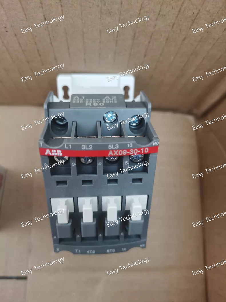
Technical Parameters Electrical Ratings Rated Control Coil Voltage (Uc): 220 – 230 V AC (50 Hz) / 230 – 240 V AC (60 Hz) Number of Poles (Main Contacts): 3 NO (normally open) Auxiliary Contacts: 1 NO (normally open) Rated Insulation Voltage (Ui): 690 V AC (IEC 60947‑4‑1) Rated Operational Voltage (Main Circuit): up to 690 V AC Rated Operational Current (IE): AC‑1: ~22 A @ 220/240 V AC (55 °C) and ~22 A @ 690 V AC (40 °C) AC‑3: ~9 A @ 220‑240 V AC; ~9 A @ 380‑440 V AC; ~7 A @ 690 V AC Rated Operational Power (AC‑3): ~2.2 kW @ 220‑240 V AC ~4 kW @ 380‑440 V AC ~5.5 kW @ 500‑690 V AC Performance & Switching Rated Operational Current (AC‑15): up to ~6 A (control duty) Rated Operational Current (DC‑13): ~0.55 A to ~6 A depending on DC voltage Maximum Breaking Capacity: ~250 A @ 440 V AC / ~90 A @ 690 V AC Conventional Free‑Air Thermal Current (Ith): ~24 A Operate Times: Coil energization to NO contact closing: ~10 ms to 26 ms Coil de‑energization to NO contact opening: ~4 ms to 11 ms Switching Frequency: AC‑1: ~600 cycles/hour AC‑3/AC‑15: ~1200 cycles/hour DC‑13: ~900 cycles/hour Mechanical: ~3600 cycles/hour Mechanical & Connection Terminal Type: Screw terminals for main, control, and auxiliary circuits Tightening Torque: ~1 N·m on all terminals Degree of Protection: IP20 (main, auxiliary, and coil terminals) Mounting: Panel or DIN‑rail compatible with appropriate accessories Dimensions: Approx. 44 mm (W) × ~77 mm (D) × ~74 mm (H) Weight: ~0.27 kg Ambient Operating Temperature: With thermal overload relay: −25 °C to +55 °C Without thermal overload relay: −40 °C to +70 °C Storage Temperature: −60 °C to +80 °C Maximum Altitude (without derating): ~3000 m
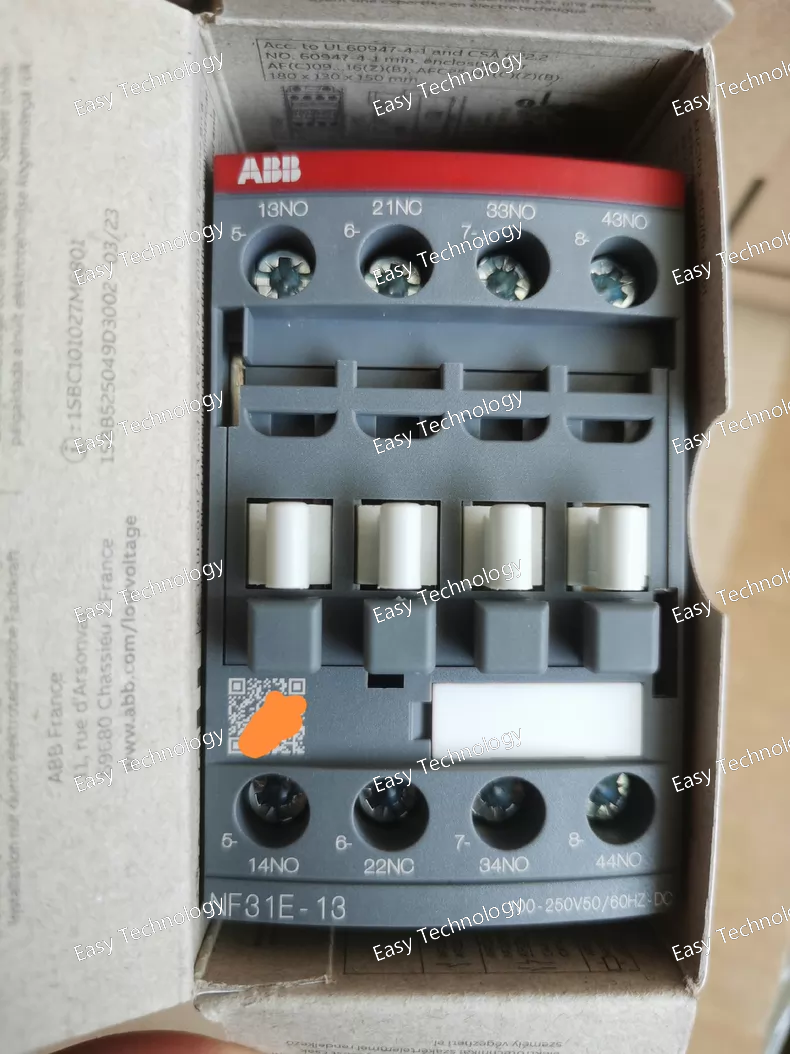
Technical Parameters Control & Coil Control (Coil) Voltage Range: 100 … 250 V AC or DC (wide range) Rated Frequency: 50 / 60 Hz Coil Type: AC/DC coil with wide voltage acceptance Contacts & Switching Contact Configuration: 3 NO + 1 NC (four auxiliary contacts total) Number of Poles: 4 Rated Insulation Voltage (Ui): up to 690 V AC Rated Operational Voltage: up to 690 V AC (auxiliary/main circuit) Conventional Free‑Air Thermal Current (Ith): 16 A Rated Operational Current (AC‑15): ~6 A @ 24 … 127 V AC ~4 A @ 220 … 240 V AC ~3 A @ 400 … 440 V AC ~2 A @ 500 … 690 V AC Rated Operational Current (DC‑13): ~6 A @ 24 V DC ~2.8 A @ 48 V DC ~1 A @ 72 V DC ~0.55 A @ 110 / 125 V DC ~0.27 A @ 220 / 250 V DC Lower DC currents at higher voltages to ~600 V DC Rated Short‑Time Withstand Current (Icw): ~140 A for 0.1 s ~100 A for 1 s Performance & Endurance Maximum Electrical Switching Frequency: AC‑15: ~1200 cycles per hour DC‑13: ~900 cycles per hour Maximum Mechanical Switching Frequency: ~6000 cycles per hour Mechanical & Installation Terminal Type: Screw terminals Mounting: DIN‑rail TH35 or panel mount with screws Dimensions: approx. 45 mm width × 77 mm depth × 86 mm height Net Weight: ~0.27 kg Degree of Protection: IP20 (housing and terminals) Operating Ambient Temperature: approx. –40 °C to +70 °C Altitude: Suitable for installations up to ~3000 m
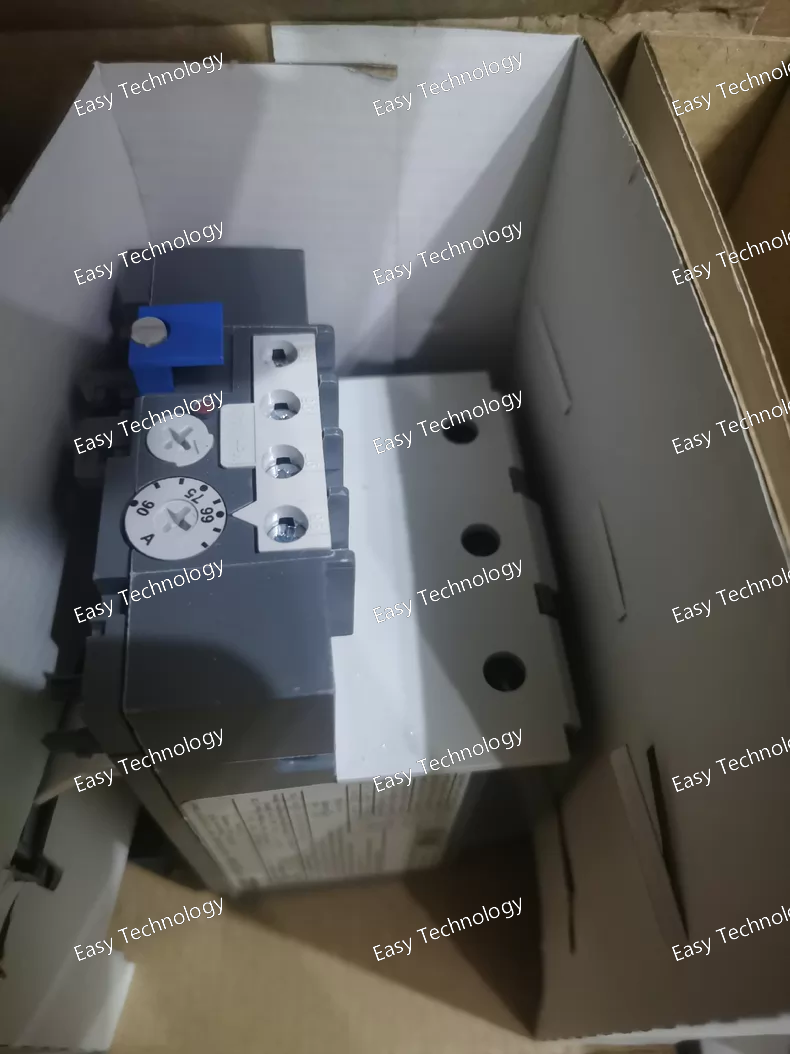
Technical Parameters Electrical Ratings Current Setting Range: ~65–90 A (adjustable) Number of Poles: 3 (protects three phases) Trip Class: 10A (industrial motor protection characteristic) Rated Operational Voltage (Main Circuit): up to 690 V AC Rated Insulation Voltage (Ui): 690 V Rated Impulse Withstand Voltage (Uimp): 6 kV Rated Frequency: 50 / 60 Hz (AC) and also operable for DC auxiliary circuits Protection & Functional Features Motor Protection: Thermal overload protection with phase loss sensitivity Reset Options: Manual or automatic reset selectable Trip‑Free Mechanism: Yes Stop & Test Functions: Integrated on front Ambient Temperature Compensation: Yes (for reliable trip response over –25 °C to +55 °C) Trip Indication: Visible on front Auxiliary Contacts Auxiliary Contact Configuration: 1 NC (normally closed) — trip contact 1 NO (normally open) — signal contact Auxiliary Contact Ratings (AC‑15): ~3 A @ 120 V AC ~1.5 A @ 240 V AC ~1.9 A @ 400 V AC ~1 A @ 440–500 V AC Auxiliary Contact Ratings (DC‑13): ~1.25 A @ 24 V DC ~0.25 A @ 125 V DC ~0.12 A @ 250 V DC Installation & Connection Mounting: Direct mount on compatible contactors (e.g., A/AF line) or separate base mounting with accessory kit Terminal Type: Screw terminals for main and auxiliary circuits Connecting Capacity: Main Circuit: Flexible/rigid conductors up to ~35 mm² Auxiliary Circuit: Flexible with ferrules ~0.75–2.5 mm², rigid up to ~4 mm² Tightening Torque: Main circuit ~7.2 … 9.6 N·m Auxiliary circuit ~1.0 … 1.3 N·m Environmental & Mechanical Degree of Protection: Housing: IP20 Main Circuit Terminals: IP10 Pollution Degree: 3 Operating Ambient Temperature: approx. –25 °C to +55 °C with compensation Storage Temperature Range: approx. –40 °C to +70 °C Mounting Position: Standard vertical orientation recommended Approx. Dimensions: ~80 mm (W) × 120 mm (H) × 120 mm (D) Net Weight: ~0.75 kg
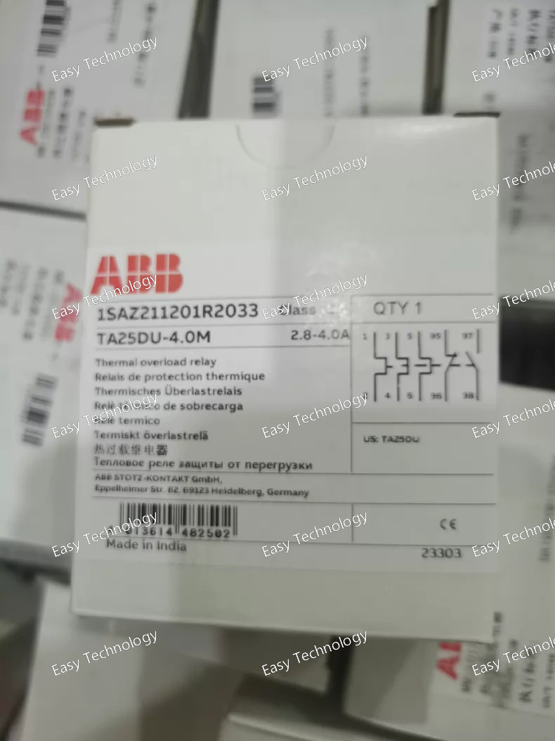
Technical Parameters Basic Electrical Ratings Type: Thermal overload relay Adjustable Current Setting Range: 2.8 … 4.0 A Rated Operational Current (Ie): 4 A Number of Poles / Protected Poles: 3 Trip Class: Class 10A Rated Insulation Voltage (Ui): 690 V Rated Impulse Withstand Voltage (Uimp): ~6 kV Rated Frequency: 50 / 60 Hz Contacts Auxiliary Contacts: 1 NC (normally closed) — trip contact 1 NO (normally open) — signal contact Contact Ratings: AC‑15 / control duties: up to ~3 A (NC) and ~1.5–1.2 A (NO) depending on voltage level Typical auxiliary rating examples: ~3 A @ 120 V AC (NC) ~1.2 A @ 240 V AC (NO) Protection & Functional Features Motor Protection: Overload protection with phase failure sensitivity Temperature Compensation: Included for stable trip performance across ambient ranges Trip‑Free Mechanism: Yes (prevents welded closed in overload) Reset Options: Manual or automatic reset selectable Stop & Test Functions: Integrated Mechanical & Installation Mounting: Direct mount on compatible ABB contactors (TA/TF series) Terminal Type: Screw terminals Connecting Capacity: Flexible conductors: 0.75 … 4 mm² Rigid conductors: 0.75 … 4 mm² Flexible with ferrules: 1 or 2 conductors per terminal Degree of Protection: IP20 on housing; IP10 at main circuit terminals Pollution Degree: 3 Physical & Environmental Approx. Dimensions: ~44 mm (W) × ~80 mm (H) × ~94 mm (D) Approx. Weight: ~0.15 kg Ambient Operating Temperature: –25 °C to +55 °C Storage Temperature Range: –40 °C to +70 °C
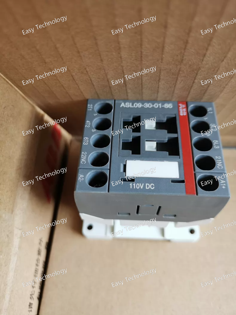
Technical Parameters General & Electrical Ratings Product Type: Electromechanical Contactor (DC operated) Series: ASL09 Number of Poles: 3 main poles Auxiliary Contacts: 1 normally closed (1 NC) built‑in auxiliary contact Rated Control Circuit Voltage (Uc): DC 110 V Rated Operational Voltage (Main Circuit): up to 690 V AC / up to 690 V AC environment rating Rated Insulation Voltage (Ui): 690 V Rated Impulse Withstand Voltage (Uimp): 6 kV Control & Coil Coil Type: DC coil designed for low consumption Coil Operating Voltage: 110 V DC Control Frequency: n/a (DC coil) Operational Performance Conventional Free‑Air Thermal Current (Ith): ~22 A Rated Operational Current (AC‑1): ~22 A at 690 V AC (temperature‑dependent) Rated Operational Current (AC‑3): ~9 A at 220–415 V AC ~8 A at 440–500 V AC ~5–7 A at 690 V AC Rated Operational Power (AC‑3): ~2.2 kW @ 220–240 V AC ~4–5.5 kW @ 400–690 V AC Rated Operational Current (AC‑15 Control): ~4 A @ 220–240 V AC ~2–3 A @ 380–690 V AC Rated Operational Current (DC‑13): ~0.55–1.1 A @ 110–125 V DC ~0.27 A @ 220–250 V DC ~2.8 A @ 400 V DC ~1–2.8 A @ 250–500 V DC Switching & Endurance Mechanical Switching Frequency: Up to ~3600 cycles/hour Electrical Switching Frequency: AC‑1: ~600 cycles/hour AC‑15 / AC‑3: ~1200 cycles/hour DC‑13: ~900 cycles/hour Operate/Release Times: ~7–21 ms to open/close contacts on coil energization/de‑energization Mechanical & Connection Terminal Type: Screw terminals Wire Stripping Length: ~9 mm Connecting Capacity: Designed for standard control and power wiring sizes Environmental & Physical Ambient Operating Temperature: −40 °C to +70 °C (varies with relay or overload fitted) Storage Temperature: −60 °C to +80 °C Degree of Protection: IP20 at terminals Maximum Permissible Altitude: ~3000 m Approx. Dimensions: ~45 mm (W) × ~68 mm (H) × ~72.5 mm (D) Net Weight: ~0.28 kg
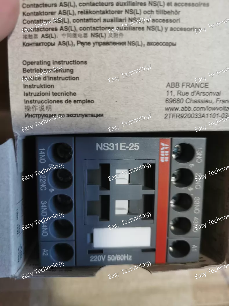
Technical Parameters Control & Contact Configuration Product Type: Contactor Relay (Auxiliary Contact Switching Unit) Number of Poles (Contacts): 4 3 Normally Open (3 NO) 1 Normally Closed (1 NC) Rated Control (Coil) Voltage: 220 V AC, 50/60 Hz Coil Type: AC magnetic coil actuation Electrical Ratings Rated Operational Voltage (Main & Auxiliary): up to 690 V AC Conventional Free‑Air Thermal Current (Ith): ~10 A (typical auxiliary circuit rating) Rated Operational Current (AC‑15): ~4 A @ 220 / 240 V AC ~3 A @ 400 / 440 V AC ~2 A @ 500 / 690 V AC Rated Operational Current (DC‑13): ~6 A @ 24 V DC ~0.55 A @ 110 V DC ~0.27 A @ 220 / 250 V DC Rated Insulation Voltage (Ui): ~690 V AC Rated Impulse Withstand Voltage (Uimp): ~6 kV Short‑Time Withstand Current (Icw): ~140 A for 0.1 s ~100 A for 1 s Switching Frequency: AC‑15: ~1200 operations/hour DC‑13: ~900 operations/hour Mechanical & Installation Terminal Type: Screw or spring terminals depending on configuration Connection Capacity: standard industrial wire sizes compatible with auxiliary control circuits Mounting: DIN‑rail or panel mount Mechanical Endurance: Designed for high cycle life in control applications Environmental & Physical Operating Ambient Temperature: approx. −40 °C to +70 °C Degree of Protection: typically IP20 (installed inside panel) Dimensions: Compact relay form factor Approximate Weight: ~0.20–0.25 kg
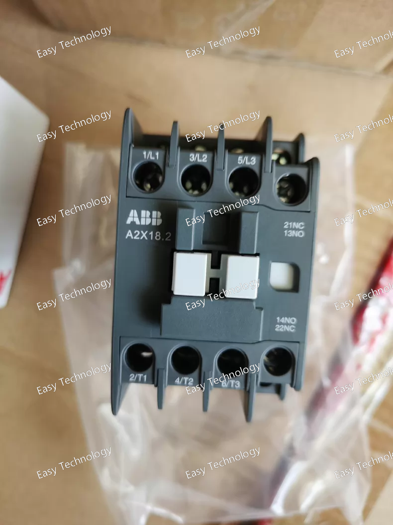
Technical Parameters Electrical Ratings Type: AC contactor, electromechanical Number of Poles: 3 main poles Auxiliary Contacts: Typically 1 NO + 1 NC (or similar auxiliary arrangement for control feedback) Rated Operational Current (AC‑1): Suitable for general power switching in low‑voltage AC circuits Control Coil Voltage: Coil variants available; common factory versions include 220–240 V AC 50/60 Hz Rated Operational Voltage (Main Circuit): Typically up to 690 V AC (depending on configuration) Compliance: Designed to meet IEC/EN 60947‑4‑1 / 60947‑1 standards for industrial contactors Performance & Capability Load Types: Three‑phase motors, resistive heating elements, inductive loads Switching Frequency: Suitable for typical industrial on/off switching cycles Durability: Engineered for long mechanical and electrical life under rated load conditions Coil Operation: AC coil actuation with reliable magnetic operation Mechanical & Installation Mounting: DIN‑rail or panel mounting (modular contactor footprint) Terminal Type: Screw clamp terminals for secure connection of power and control wiring Connection Capacity: Designed for standard industrial cable sizes compatible with the contactor’s current rating Mechanical Construction: Rugged, compact housing suitable for control panels and distribution boards Environmental Operating Temperature Range: Typical industrial ambient range Degree of Protection: IP20 at terminals (installed inside enclosure) Typical Applications Motor starting and stopping Industrial automation controls Lighting and heating circuit switching Power distribution panels
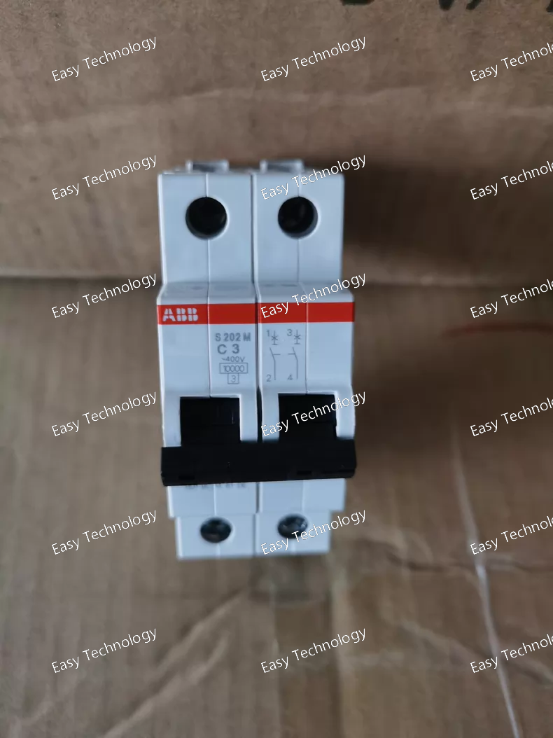
Technical Parameters Electrical Ratings Rated Current (In): 3 A (C‑curve) Number of Poles: 2P (two poles) Rated Operational Voltage: up to 400 V AC (IEC standards) / 440 V AC Rated Insulation Voltage (Ui): 440 V Rated Frequency: 50 / 60 Hz Rated Short‑Circuit Breaking Capacity (Icn): 10 kA at 230/400 V AC Rated Ultimate Breaking Capacity (Icu): up to 15 kA Current Limiting Class: 3 Overvoltage Category: III Rated Impulse Withstand Voltage (Uimp): 4 kV Operational Voltage Range: 12 V AC/DC — 440 V AC (typical) DC Interrupting Capability (approx.): up to 125 V DC Contact Position Indication: Red “ON” / Green “OFF” Mechanical & Installation Mounting: Standard DIN‑rail (TH35) mounting Terminal Type: Screw terminals with bi‑directional cylinder‑lift design Tightening Torque: ~2 N·m Mechanical Endurance: ~20,000 operations Electrical Endurance: ~20,000 AC cycles Mounting Position: Any orientation allowed Housing Material / Color: Group II insulation, RAL 7035 light grey Auxiliary Accessories: Compatible with bottom‑fitting auxiliary contacts and other add‑ons in the S200M range Environmental & Physical Ambient Operating Temperature: approximately ‑25 °C to +55 °C Pollution Degree: 3 Protection: IP20 (with enclosure) Dimensions (approx.): Width: 2 modules (~35 mm) Height: ~88 mm Depth: ~69 mm Weight: ~0.25 kg
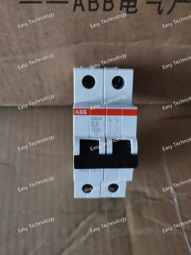
Technical Parameters Electrical Ratings Rated Current (In): 2 A (C‑curve) Number of Poles: 2P Rated Operational Voltage: up to 400 V AC (IEC 60898‑1) / 440 V AC (IEC 60947‑2) Rated Insulation Voltage (Ui): 440 V Rated Frequency: 50 / 60 Hz Rated Short‑Circuit Breaking Capacity (Icn): 10 kA at 230 / 400 V AC Rated Ultimate Short‑Circuit Breaking Capacity (Icu): up to 15 kA Current Limiting Class: 3 Overvoltage Category: III Rated Impulse Withstand Voltage (Uimp): 4 kV Operational Voltage Range: 12 V AC/DC — 440 V AC DC Interrupting Capability: up to 125 V DC Red/Green Contact Position Indication: ON (red) / OFF (green) Standards Compliance: IEC/EN 60898‑1, IEC/EN 60947‑2 Mechanical & Mounting Mounting: Standard DIN‑rail (TH35) Terminal Type: Screw terminals; bi‑directional cylinder‑lift design Tightening Torque: ~2 N·m Mechanical Endurance: ~20,000 operations Electrical Endurance: ~20,000 AC cycles Mounting Position: Any Housing Material / Color: Group II insulation, light grey Auxiliary Accessories: Optional bottom‑fitting auxiliary contact compatible with S200M series Environmental & Physical Ambient Operating Temperature: −25 °C to +55 °C Pollution Degree: 3 Protection: IP20 (with enclosure) Dimensions (approx): Width: 2 modules (~35 mm), Depth: ~69 mm, Height: ~88 mm Weight: ~0.25 kg
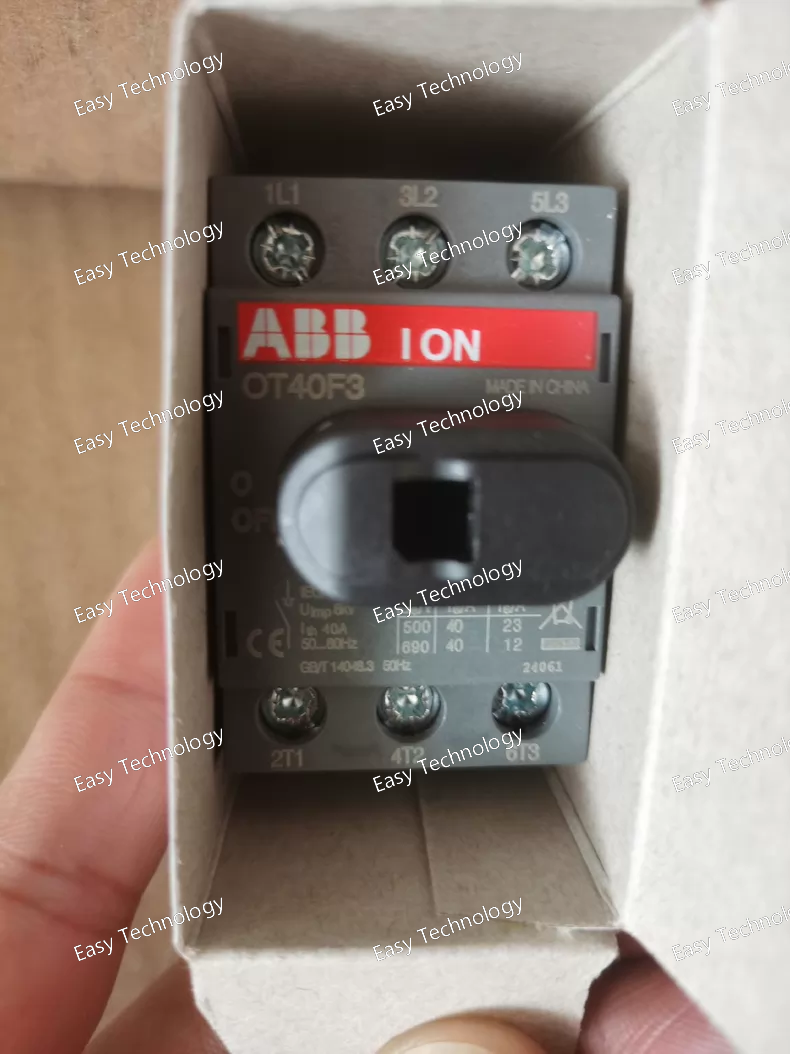
Technical Parameters Electrical Ratings Rated Operational Current (Ie): 40 A (AC‑21A / AC‑22A) Rated Operational Voltage: Up to 750 V AC (max) Rated Operational Power (AC‑23A): 11 kW @ 400–415 V AC ~5.5 kW @ 220–240 V AC Rated Insulation Voltage (Ui): ~750 V Rated Short‑Time Withstand Current (Icw): ~0.5 kA Rated Short‑Circuit Making Capacity (Icm): ~0.7 kA (690 V) Utilization Category: Suitable for mains isolation and load‑break duties Frequency: 50/60 Hz Mechanical & Installation Number of Poles: 3 Operating Mode: Front‑operated manual handle Handle & Shaft: Not included (ordered separately) Mounting Type: Base mountable; DIN‑rail compatible Terminal Type: Screw terminals Conductor Size Range: ~0.75 … 10 mm² (Cu) Tightening Torque: ~0.8 N·m Mechanical Durability: ~20,000 operations Protection & Environmental Degree of Protection (Front): IP20 Pollution Degree: 3 Standards Compliance: IEC 60947‑3, UL 508, CSA C22.2 No.14 Ambient Temperature: Typical industrial range Physical Data Approx. Width: ~35 mm Approx. Height: ~68 mm Approx. Depth: ~56 mm Approx. Weight: ~0.09 kg
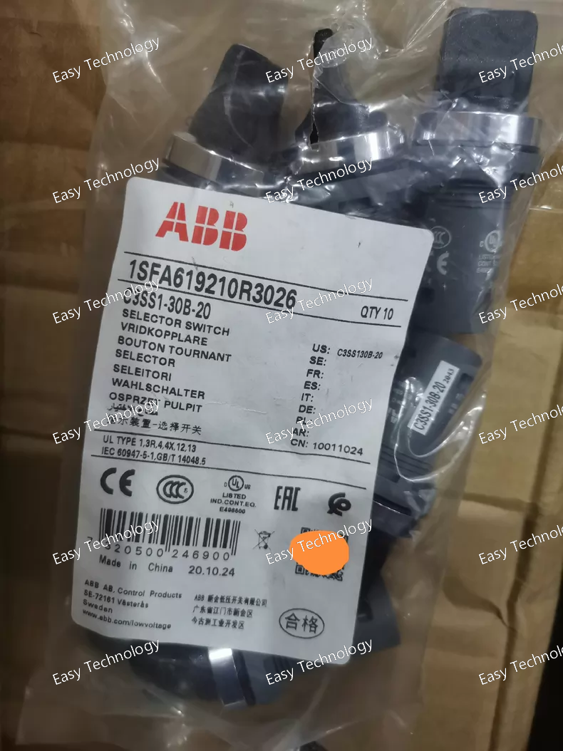
Technical Parameters General Characteristics Product Type: Selector Switch Family / Series: Compact selector switch Actuator Type: Short handle knob, non‑illuminated Number of Positions: 3 (maintained in all positions) Operation Mode: Maintained (not spring‑return) Electrical Ratings Rated Operational Voltage: up to 300 V AC/DC Rated Current (AC‑15): approx. 2 A @ 240 V AC Rated Current (DC‑13): approx. 0.3 A @ 24 V DC (typical) Contact Configuration: 2 Normally Open (2 NO), 0 Normally Closed (0 NC) Rated Insulation Voltage: typically around 300 V Rated Impulse Withstand Voltage: approx. 6 kV (typical for compact pilot devices) Mechanical & Connection Panel Cut‑out / Mounting Hole: 22 mm diameter for standard industrial controls Bezel / Front Ring: Chrome metal Terminal Type: Screw terminals Mechanical Durability: Typically ~500,000 operations Handle Color: Black Environmental & Protection Degree of Protection: IP20 (front) with compatibility for higher NEMA/IP enclosure ratings (NEMA 1, 3R, 4X, 12, 13) Operating Temperature: approx. ‑25 °C to +70 °C Storage Temperature: approx. ‑40 °C to +85 °C Mounting: Panel mount with secure nut/clip
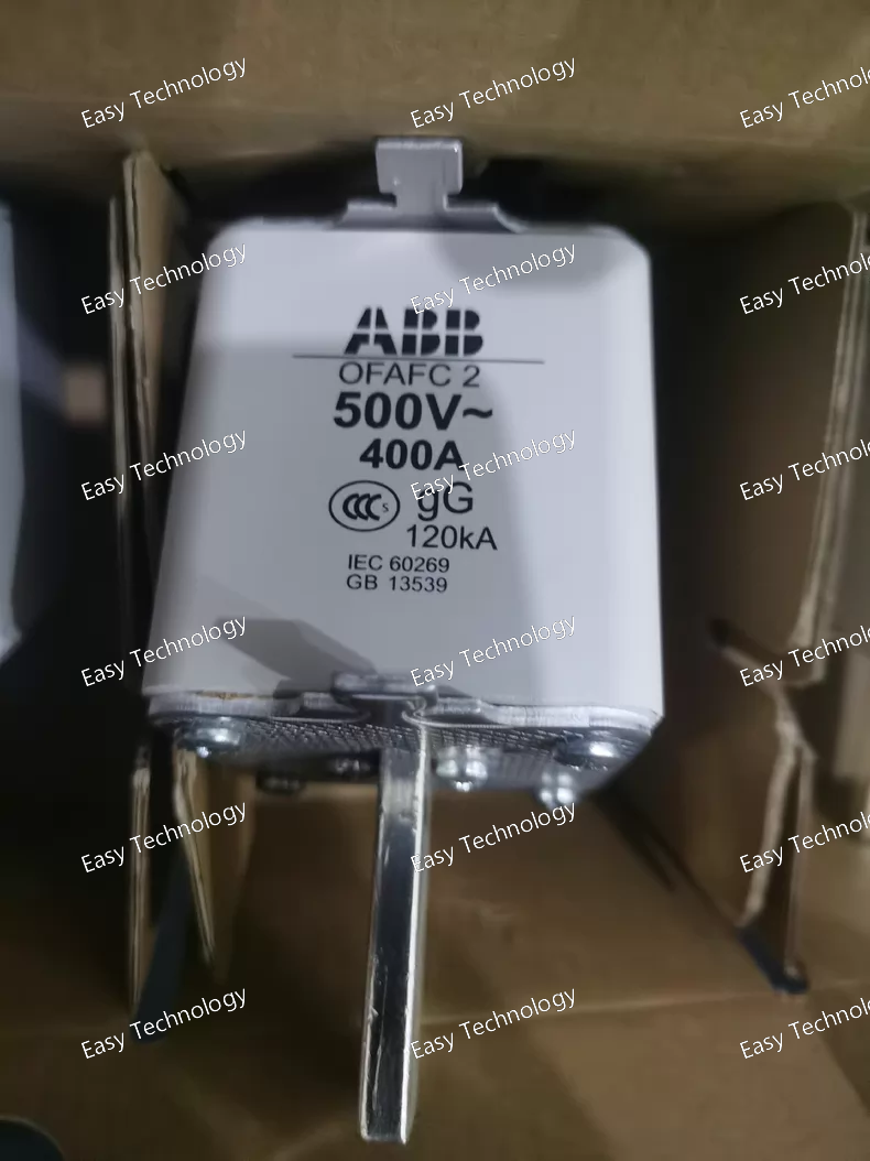
Technical Parameters Electrical Ratings Rated Current: 400 A Utilization Category: gG (general purpose protection for overloads and short circuits) Rated Voltage: 500 V AC (typical application voltage for low‑voltage systems) Breaking Capacity: High Rupturing Capacity suitable for up to approx. 80 kA short‑circuit currents at rated voltage Fuse Size / Type: Size 2 “C2” (NH2 / flat knife fuse link style) used in compatible fuse holders Standards Compliance: Designed to meet IEC/EN 60269 series for low‑voltage HRC fuse links Functional Summary Type: High Rupturing Capacity Fuse Link Current Rating: 400 A Voltage Rating: up to 500 V AC Protection Category: gG (general purpose) Breaking Capacity: ~80 kA class for robust fault interruption Usage & Application The ABB OFAFC2GG400 is suitable for: Protection of distribution circuits in industrial, commercial and utility systems Use in NH‑type fuse holders / switch‑fuse disconnectors Motor feeders, transformer protection, cable trains, and general overload/short‑circuit safeguarding Backup protection ahead of circuit breakers
 TEL: Grace +86 13600179521
  Mail: info@hongkongeasy.com jilineasyyi@outlook.com
 Q Q:615739355
 ADDRESS:Unit 12, 20th Floor, Good View Commercial Centre, 2-16 Garden Street, Mong Kok, Hong Kong
 whats app


