
Industrial Controller
All product are in stock,guaranteed delivery within 3-7 days.


PRODUCT
PICTURE
BRAND
DESCRIBE
STOCK
DOWNLOAD
Technical Parameters Parameter Specification Product Series CP Series (Compact Plug-in Relay) Model Decoding CP1-10R-10 • CP1: Basic series designation. • 10: Nominal Coil Voltage = 24V DC. (Note: In common CP series coding, "10" often corresponds to 24V DC. "12" is 12V DC. Always verify.) • R: Contact Arrangement = 1 Changeover (Form C, 1 CO). • 10: Final code, typically indicating a 10A contact rating. Contact Configuration 1 Changeover (Form C / SPDT) - 1 Common (C), 1 Normally Open (NO), 1 Normally Closed (NC). Contact Material Fine Silver or Silver Alloy. Rated Load (Resistive) 10A @ 250V AC 10A @ 30V DC Maximum Switching Voltage 250V AC, 30V DC Maximum Switching Power 2,500 VA (AC), 300 W (DC) Minimum Switching Load 100 mA at 5V DC (to ensure reliable contact cleaning). Coil Voltage 24V DC (Nominal). Standard operating range: 19.2V DC to 28.8V DC (80% - 120% of nominal). Coil Power Consumption Approx. 0.9W (for DC coil). Nominal Coil Current Approx. 37.5 mA @ 24V DC. Operate Time Typically ≤ 10 ms. Release Time Typically ≤ 5 ms. Electrical Life ≥ 100,000 operations at rated resistive load. Mechanical Life ≥ 10,000,000 operations (no load). Insulation Resistance > 100 MΩ (at 500V DC). Dielectric Strength (Hi-Pot) Coil to Contacts: 4,000V AC, 50/60Hz for 1 min. Between Open Contacts: 1,000V AC, 50/60Hz for 1 min. Ambient Temperature Range -40°C to +70°C (Operation and storage). Shock & Vibration Resistance Suitable for standard industrial environments. Mounting Pluggable onto a standard 8-pin or 10-pin socket (e.g., ABB PF083A or PF103A). Socket is DIN-rail or PCB mountable. Terminals (via Socket) Screw clamp terminals on the socket. Standards Compliance IEC/EN 61810-1, UL 508, CSA C22.2 No. 14, CE, RoHS. Safety Approvals UL Recognized (Component), CSA Certified. Dimensions (Relay only) Approx. 20mm (W) x 10mm (H) x 25mm (D) (for 8-pin type). Dimensions vary slightly by pin count. Weight Approx. 15g.
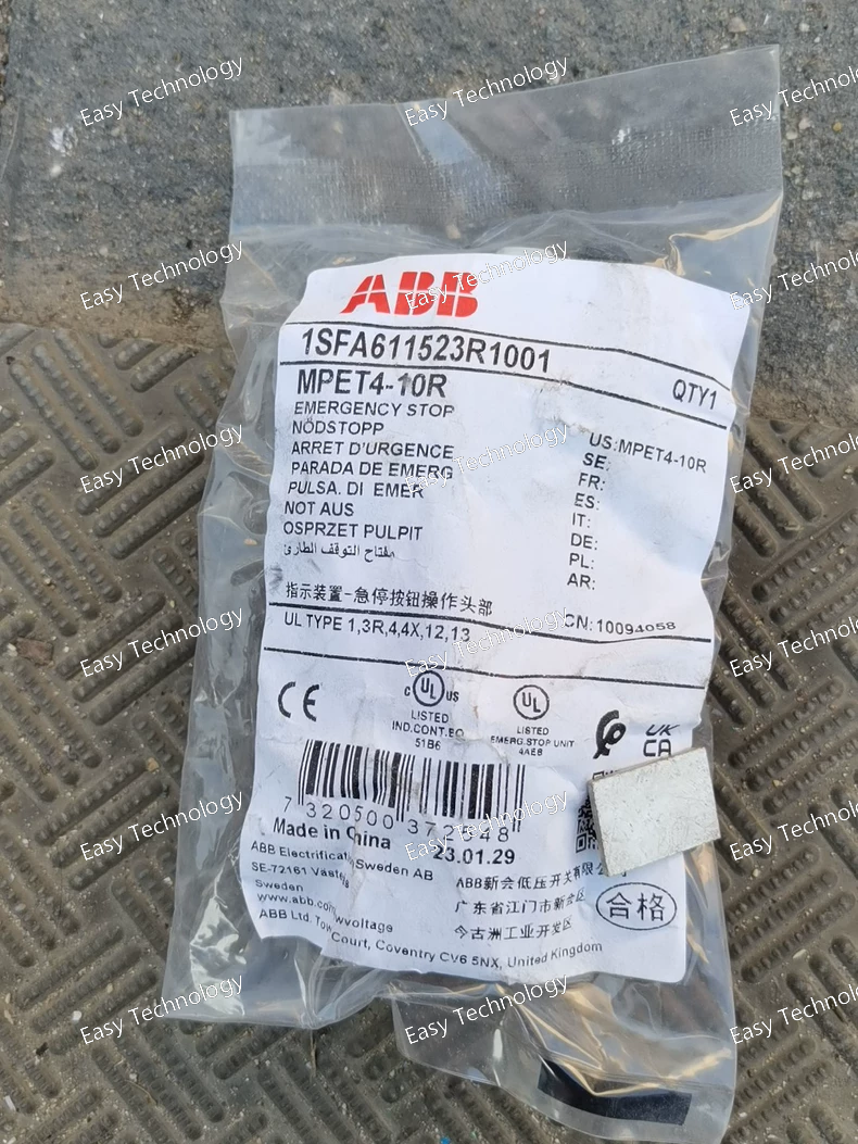
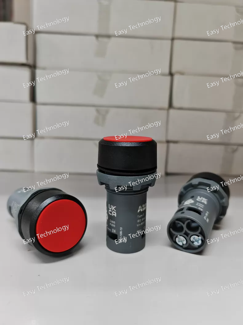
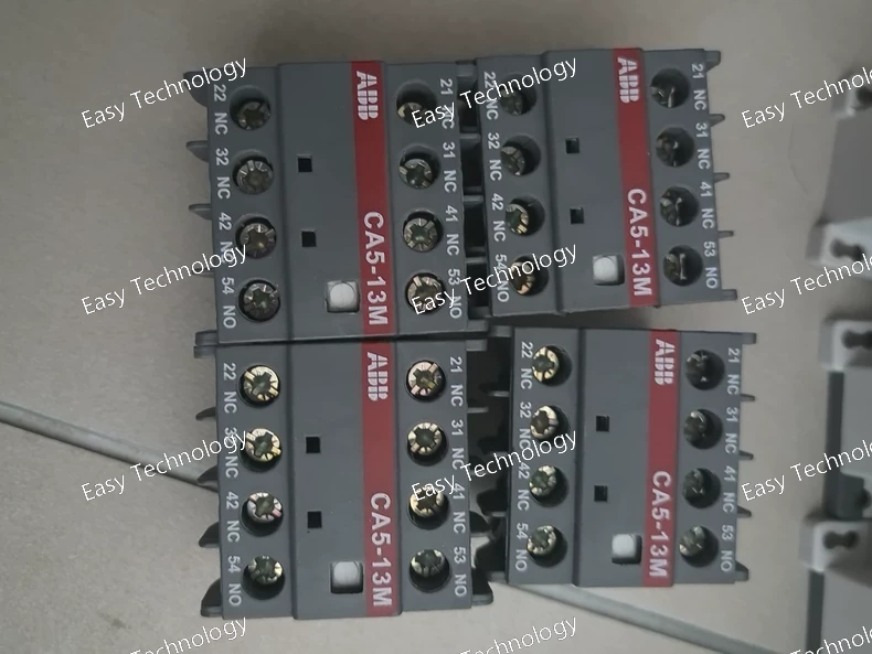
Technical Parameters Parameter Specification Product Series MPT / MET Series (Thermal Overload Relay) Model Decoding MPET4-10R • MPET: Series and frame size designation. • 4: Likely indicates the current range setting scale or frame size level (e.g., covering a specific FLA range). • 10: Trip Class 10. This means it will trip within 10 seconds at 720% of its set current. • R: Manual Reset operation. Rated Operational Current (Iᵉ) Depends on the specific "4" frame. Typical range for an MPET4 is approximately 0.11A - 25A (or similar). The exact adjustable range is critical and must be verified. Trip Class Class 10 (Standard for general-purpose motors). Poles / Protected Phases 3 Poles (for three-phase motor protection). Ambient Temperature Compensation Yes, typically for -20°C to +60°C. Trip Current Adjustment Continuous dial adjustment within the relay's specified range (e.g., 0.11 - 0.16A up to 18 - 25A). Auxiliary Contacts Typically: • 1 NO (97-98) - Can be used for trip indication. • 1 NC (95-96) - Connected to break the contactor coil circuit. Configuration may vary. Reset Mode Manual Reset (R). Requires physical push-button reset after a trip. Mounting Direct snap-on/plug-on mounting to the side of compatible ABB contactors (e.g., AF09, AF12, AF16, etc.). Can also be mounted separately with a bus kit. Compatible Contactors ABB A, AF, AX series of corresponding sizes. Standards & Approvals IEC/EN 60947-4-1, UL 508, CSA C22.2 No. 14, CE, CCC. Electrical Durability ≥ 5,000 operating cycles (at rated current). Mechanical Durability ≥ 10,000 operating cycles. Screw Terminals For main power (L1, L2, L3 / T1, T2, T3) and auxiliary contacts. Insulation Voltage 690V / 1000V (Ui / Ue). Utilization Category AC-3 (Squirrel cage motor switching).
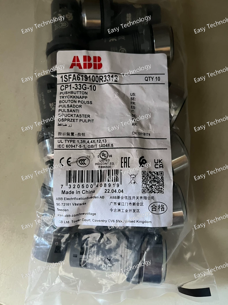
Technical Parameters Parameter Specification Product Series CP Series (Compact Plug-in Relay) Model Decoding CP1-33G-10 • CP1: Series designation. • 33: Nominal Coil Voltage = 110V AC (Common code: 33 often corresponds to 110V AC, 50/60Hz). • G: Contact Arrangement = 3 Changeover (3 Form C / 3PST-NO/NC). • 10: Variation code, typically indicating a 10A per contact rating. Contact Configuration 3 Changeover (3 Form C) - 3 poles, each with Common (C), Normally Open (NO), and Normally Closed (NC) terminals. Contact Material Silver Alloy (e.g., AgSnO₂) for high arc resistance and long life. Rated Load (Resistive, per contact) 10A @ 250V AC 10A @ 30V DC Maximum Switching Voltage 250V AC, 30V DC Maximum Switching Power (per contact) 2,500 VA (AC), 300 W (DC) Coil Voltage 110V AC, 50/60 Hz. Operable within a standard range (e.g., 80% to 110% of nominal). Coil Power Consumption Approx. 2.2 VA (for AC coil). Nominal Coil Current Approx. 20 mA @ 110V AC. Operate / Release Time Typically ≤ 20 ms. Note: AC coils have inherent zero-crossing behavior affecting timing. Electrical Life ≥ 100,000 operations at rated resistive load. Mechanical Life ≥ 10,000,000 operations (no load). Insulation Resistance > 100 MΩ (at 500V DC). Dielectric Strength (Hi-Pot) Coil to Contacts: 4,000V AC, 50/60Hz for 1 min. Between Open Contacts: 1,500V AC, 50/60Hz for 1 min. Between Poles: 2,000V AC, 50/60Hz for 1 min. Ambient Temperature Range -40°C to +70°C (Operation). Mounting Pluggable onto an 11-pin socket (e.g., ABB PF113A). The socket is DIN-rail mountable. Terminals (via Socket) Screw clamp terminals on the socket. Standards Compliance IEC/EN 61810-1, UL 508, CSA C22.2 No. 14, CE, RoHS. Safety Approvals UL Recognized, CSA Certified. Dimensions (Relay only) Approx. 29mm (W) x 25mm (H) x 36mm (D). Weight Approx. 55g.
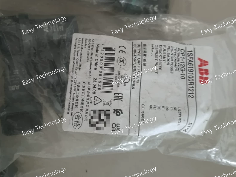
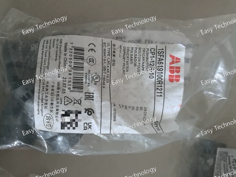
Technical Parameters / Specifications Parameter Specification Product Series CP Series (Compact Plug-in Relay) Model Decoding CP1-12G-10 • CP1: Basic series designation. • 12: Nominal Coil Voltage = 12V DC. • G: Contact Arrangement = 1 Changeover (Form C, 1 CO). (Note: 'G' often denotes a specific, higher-power variant within the 1CO range). • 10: Variation code, typically confirming a 10A contact rating. Contact Configuration 1 Changeover (Form C / SPDT) - 1 common (C), 1 normally open (NO), 1 normally closed (NC). Contact Material Fine Silver or Silver Alloy (AgSnO₂). Rated Load (Resistive) 10A @ 250V AC 10A @ 30V DC Maximum Switching Voltage 250V AC, 30V DC Maximum Switching Power 2,500 VA (AC), 300 W (DC) Minimum Switching Load 100 mA at 5V DC (for reliable contact wiping). Coil Voltage 12V DC (Nominal). Standard operating range: 9V DC to 15V DC. Coil Power Consumption Approx. 1.1 W (for DC coil). Nominal Coil Current Approx. 92 mA @ 12V DC. Operate Time Typically ≤ 15 ms. Release Time Typically ≤ 10 ms. Electrical Life ≥ 100,000 operations at rated resistive load. Mechanical Life ≥ 10,000,000 operations (no load). Insulation Resistance > 100 MΩ (at 500V DC). Dielectric Strength (Hi-Pot) Coil to Contacts: 4,000V AC, 50/60Hz for 1 min. Between Open Contacts: 1,000V AC, 50/60Hz for 1 min. Between Poles & Frame: 2,500V AC, 50/60Hz for 1 min. Ambient Temperature Range -40°C to +70°C (Operation and storage). Shock & Vibration High resistance, suitable for industrial environments. Mounting Pluggable onto a standard 11-pin socket (e.g., ABB PF113A). The socket is DIN-rail mountable. Terminals (via Socket) Screw clamp terminals on the socket for secure wiring. Standards Compliance IEC/EN 61810-1, UL 508, CSA C22.2 No. 14, CCC, CE, RoHS. Safety Approvals UL Recognized (Component), CSA Certified. Dimensions (Relay only) Approx. 29mm (W) x 25mm (H) x 36mm (D). Weight Approx. 40g.
Technical Parameters Parameter Specification Product Series CP Series (Compact Plug-in Relay) Model Decoding CP1-12R-10 • CP1: Basic series designation. • 12: Nominal Coil Voltage = 12V DC. • R: Contact Arrangement = 1 Changeover (Form C, 1 CO). • 10: Variation code, often indicating 10A contact rating and/or pin layout. Contact Configuration 1 Changeover (Form C / SPDT) - 1 pole, common, normally open (NO), normally closed (NC). Contact Material Silver Alloy (AgSnO₂, AgNi, etc.) Rated Load (Switching Capacity) 10A @ 250V AC / 10A @ 30V DC (Resistive Load). This is the maximum current it can reliably switch. Maximum Switching Voltage 250V AC, 30V DC Maximum Switching Power 2,500 VA (AC), 300 W (DC) Coil Voltage 12V DC (Nominal). Operable within a range (e.g., 9V DC to 15V DC). Coil Power Consumption Approx. 0.9W (for DC coil). Nominal Coil Current Approx. 75 mA @ 12V DC. Operate Time Typically < 10 ms. Release Time Typically < 5 ms. Electrical Life ≥ 100,000 operations at rated load. Mechanical Life ≥ 10,000,000 operations (no load). Insulation Resistance > 100 MΩ (at 500V DC). Dielectric Strength Coil-Contacts: 4,000V AC, 50/60Hz for 1 min. Between Open Contacts: 1,000V AC, 50/60Hz for 1 min. Ambient Temperature Range -40°C to +70°C (Operation). Shock & Vibration Resistance High, suitable for industrial environments. Mounting Pluggable onto a standard 8 or 10-pin socket (e.g., ABB PF083A, PF103A). Socket is typically DIN-rail or PCB mountable. Terminals Plug-in pins. Standards Compliance IEC/EN 61810-1, UL 508, CSA C22.2 No. 14, CE, RoHS. Dimensions (L x W x H) Approx. 29mm x 12.5mm x 25mm (excluding pins). Weight Approx. 20g.
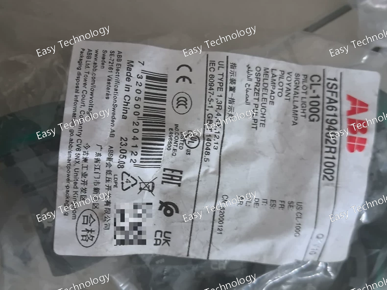
Technical Parameters Parameter Specification / Decoding Product Line ABB Cable Glands / Cable Accessories Type Plastic Cable Gland, EMC Shielding Type (Metal-Sprayed) Part Number Decoding CL-100Gywms • CL: Likely denotes Cable Level or Clamp series. • 100: The entry thread size. This is M40x1.5 (Metric 40mm thread, pitch 1.5mm). This is the size that screws into the enclosure. • G: Likely indicates a specific gland series or design (e.g., standard straight-through). • yw: Yellow-White color, typically associated with PA12 Polyamide material (good mechanical strength, UV resistance, chemical resistance). • ms: Metal-Sprayed (EMC version). Provides conductivity for grounding cable screens. Thread Size (Enclosure Entry) M40 x 1.5 (Metric) Sealing Range (Cable Ø) Typically 13 - 25 mm (This is the outer diameter range of the cable sheath that the gland can effectively clamp and seal). (Must verify with official datasheet) Material (Body & Nut) Polyamide 12 (PA12), Halogen-free, V0 flammability rating. Color: Yellow-White (RAL-like). EMC Shielding Yes. Metal-sprayed surface provides contact for cable screens/shields. Surface Resistance: Typically < 100 mΩ. Sealing Ring Material Often Silicone (SI) or EPDM rubber, integrated. Ingress Protection (IP Rating) Up to IP68 / IP69K when properly installed on a compatible enclosure and cable. Temperature Range -40°C to +100°C (for PA12 material, stationary use). UV Resistance Good (typical for PA12 yellow-white material). Standards Compliance IEC 62444 (Cable glands). EMC: Contributes to compliance with IEC/EN 61000-6-2 and -6-4. RoHS & REACH compliant. Corrosion Resistance Excellent resistance to oils, fuels, and many chemicals. Mounting Torque Refer to datasheet (e.g., 40-50 Nm for M40 size). Certifications May have UL, CSA, GL (marine) depending on specific variant.
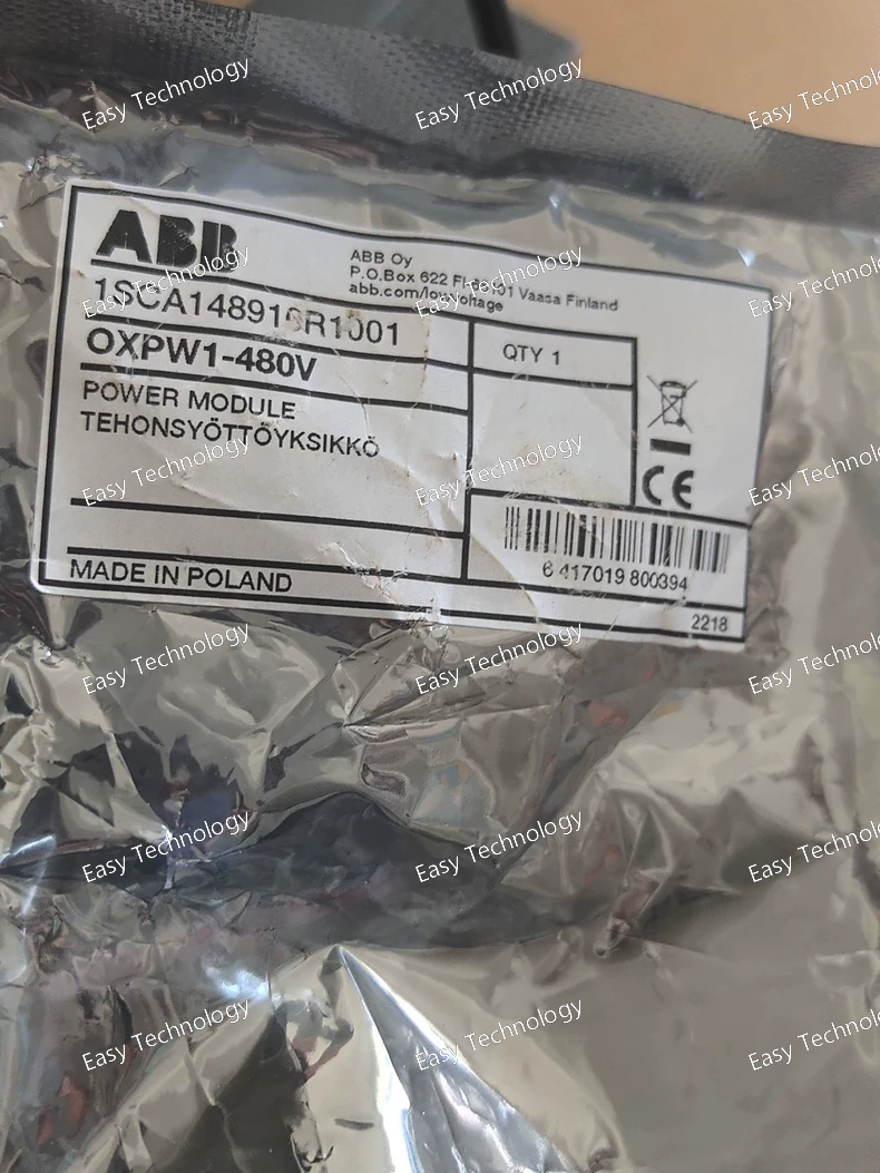
Technical Parameters Parameter Specification Manufacturer Part Number OXPW1-480V Product Line ABB XSeries (PLC / Smart Relay System) Module Type Power Supply Module (PSU) Input Voltage 480V AC, single-phase (+10%, -15%). Frequency: 50/60 Hz. Input Current Approximately 0.2A at 480V AC (typical). Output Voltage 24V DC (regulated), supplied to the connected XSeries CPU and expansion I/O modules via the backplane connector. Output Current / Power Typically supplies up to ~1.0A at 24V DC (≈ 24W) to the system. Note: This is shared between CPU and all connected I/O modules. Inrush Current Limiting Yes, to prevent nuisance tripping of the upstream fuse/circuit breaker. Internal Protection Input Fuse: Integrated, user-replaceable fuse (e.g., 2A, 250V, time-delay type). Output: Overload and short-circuit protection. Isolation Reinforced isolation between input (AC mains) and output (24V DC system) as per safety standards. Status Indicator (LED) Green PWR LED: Illuminates when input voltage is present and output is within normal range. Connection Input: Screw terminal block for Line (L) and Neutral (N) AC connection. Output: Via plug-in connector to the CPU backplane. Mounting Standard 35mm DIN Rail (EN 60715). Mounts to the left of the CPU module. Operating Temperature 0°C to +55°C (without derating). Storage Temperature -25°C to +70°C. Humidity 5% to 95% non-condensing. Altitude Up to 2000m without derating. Safety Standards Complies with UL 508 (Industrial Control Equipment), IEC/EN 61131-2 (Programmable Controllers). CE marked. EMC Standards Complies with IEC/EN 61000-6-2 (Immunity) and IEC/EN 61000-6-4 (Emission) for industrial environments. Dimensions (W x H x D) Approx. 45mm x 110mm x 75mm (Specific to the XSeries power module form factor). Weight Approx. 0.3 kg.
Technical Parameters Parameter Specification Product Range / Series System Pro M compact, S200 Series Type Miniature Circuit Breaker (MCB) Poles 1 Pole (1P) Rated Current (In) 13A Tripping Characteristic (Curve) C Curve (Medium Starting Current). • Thermal Trip: 1.13 to 1.45 x In (Time-delayed). • Magnetic Trip: 5 to 10 x In (Instantaneous). Rated Operational Voltage (Ue) 230/400V AC Rated Insulation Voltage (Ui) 500V AC Rated Impulse Withstand Voltage (Uimp) 6 kV Rated Frequency 50/60 Hz Rated Breaking Capacity (Icn) 6 kA (6,000 Amps) at 230/400V AC according to IEC/EN 60898-1. 10 kA (10,000 Amps) according to IEC/EN 60947-2. Utilization Category A (for general use, no intentional time delay) Terminals • Upper/Lower: Suitable for both incoming and outgoing connections. • Cable Range: 1 - 25 mm² (solid/stranded) • Torque: 2.0 - 2.5 Nm (for terminal screws M5) Mechanical Endurance 20,000 operating cycles (make & break at no load) Electrical Endurance 10,000 operating cycles (at rated current In) Ambient Temperature Range -25°C to +60°C (for calibration, reference temp is +30°C) Mounting DIN Rail EN 60715 (35mm) Width (Modular Size) 17.5 mm (1 module) Standards Compliance IEC/EN 60898-1 (Domestic and similar use). IEC/EN 60947-2 (Industrial use). CCC, CE, KEMA, etc. Pollution Degree 2 Protection Degree (IP Code) IP20 (when installed in an enclosure) Connection Capacity Up to 2 x 25mm² cables or 1 x 35mm² cable per terminal (depending on type).
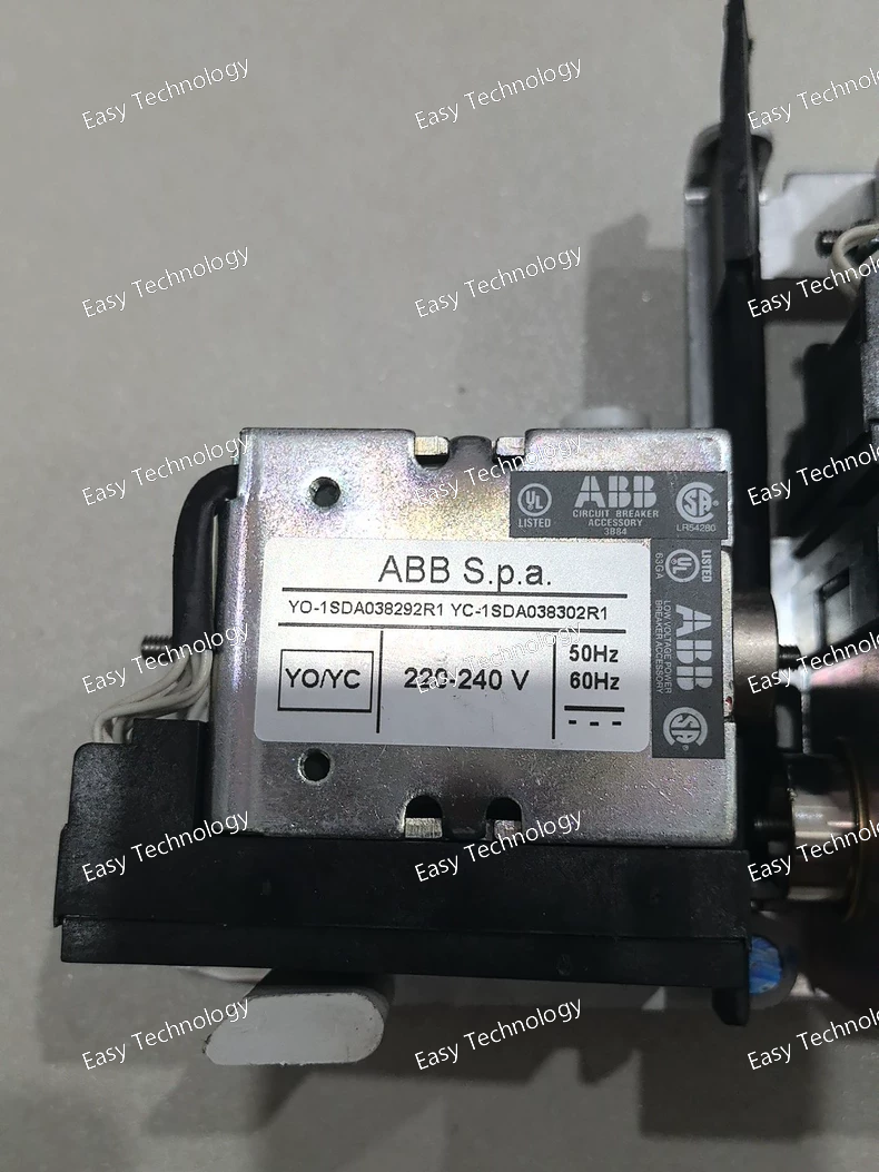
Technical Parameters Parameter Specification Manufacturer Part Number YU-1SDA038292R1 (Commercial Reference) Product Series / Type CP-S (CP Series Switching Power Supply) Rated Output 24V DC, 2.5A Output Power 60W (24V * 2.5A) Input Voltage Range (AC) 220-240V AC, single-phase, 50/60 Hz. (Note: Often designed for a specific range like 200-240V or a global range 85-264V – this specific model is for 220-240V). Input Current Typically ~0.5A at 230V AC. Inrush Current Limiting Yes, to protect internal components and prevent nuisance tripping of upstream breakers. Output Voltage Adjustment Usually via a small potentiometer to fine-tune output (e.g., 24V ±5%). Line Regulation < ±1% for input voltage variation. Load Regulation < ±2% for load variation (0% to 100%). Ripple & Noise Typically < 150mV peak-to-peak. Efficiency Typically > 85%. Protections Output: Short-circuit (SC), Overload (OL), Overvoltage (OVP). Input: Fuse protection. Isolation Voltage (Input-Output) Typically 3000V AC or 4000V AC. Cooling Method Convection cooling (fanless). Operating Temperature -25°C to +70°C (with derating above ~60°C). Storage Temperature -40°C to +85°C. Housing Material Metal (for heat dissipation) or robust plastic. Mounting Standard 35mm DIN Rail (EN 60715). Terminals Screw clamp terminals for input (AC) and output (DC). Safety & EMC Standards Complies with IEC/EN/UL 62368-1 (Safety), IEC/EN 61000-6-2 (Immunity), IEC/EN 61000-6-4 (Emission). CE marked. Protection Class / Degree IP20 (for installation inside an enclosure). Dimensions (W x H x D) Approx. 70mm x 90mm x 55mm (varies slightly; example: 70x90x55mm).
Technical Parameters Parameter Specification Product Range DXN Q Series Type RCBO (Residual Current Breaker with Overcurrent protection) Poles / Protected Poles 2 Poles (1P+N) Rated Current (In) Typically 20A (Other ratings like 16A, 25A, 32A, 40A may exist in the Q35 series – verify specific model code). Tripping Characteristic C Curve (Medium start-up characteristic, suitable for inductive and general loads). Rated Residual Current (IΔn) 30 mA (Standard for personal protection against electric shock). Residual Current Type Type A (AC and pulsating DC sensitive). Rated Operational Voltage (Ue) 230V AC Rated Insulation Voltage (Ui) 500V Rated Impulse Withstand Voltage (Uimp) 6 kV Rated Breaking Capacity (Icn) Typically 6000A (6 kA) at 230/400V AC. Utilization Category AC: According to IEC/EN 61009-1 Mechanical Endurance 20,000 operating cycles Electrical Endurance 6,000 operating cycles (at In) Terminal Torque 2.0 - 2.5 Nm Connection Capacity (Rigid Cable) 25 mm² Connection Capacity (Flexible Cable) 16 mm² Width (Modular) 35 mm (2 modules) Mounting DIN Rail EN 60715 (35mm) Standards Compliance IEC/EN 61009-1, IEC/EN 60947-2 Ambient Temperature -25°C to +60°C (Operation) Pollution Degree 3 Protection Degree IP20 (installed in enclosure)
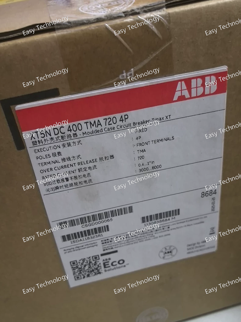
Technical Parameters Specification Details Product Type Low‑Voltage Molded Case Circuit Breaker (MCCB) Series / Model ABB Tmax XT5N 400 TMA 720 4P Rated Current (In) 400 A Number of Poles 4 (3 phases + neutral) Trip Unit Type TMA (Thermal‑Magnetic Adjustable) Trip Setting Range Adjustable for overload/current protection (typical range includes 280–400 A) Rated Insulation Voltage (Ui) 1000 V Rated Impulse Withstand Voltage (Uimp) 8 kV Rated Operational Voltage (Ue) Up to 690 V AC / suitable DC range depending on installation practice Interrupting Capacity (Icu / Ics) High interrupting capacity for AC and DC systems, suitable for heavy distribution systems Connection Type Front (FF) terminals Standards Compliance Designed to meet IEC / EN low‑voltage circuit breaker standards Mechanical Durability High cycle life typical for industrial breakers Electrical Durability Designed for many electrical switching operations Mounting Style Fixed‑mounted breaker for panel installation
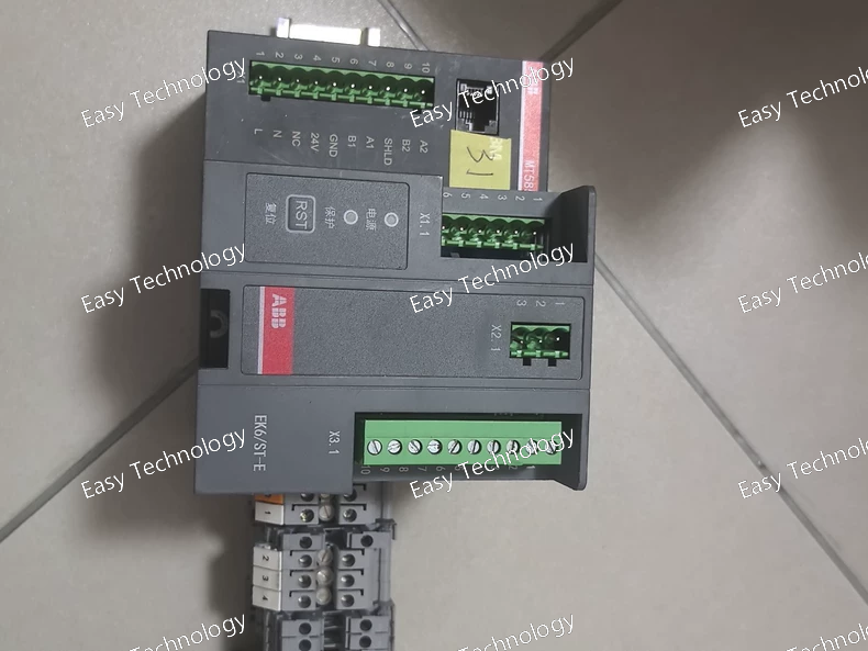
Technical Parameters Specification Typical Value / Function Product Type Medium-voltage motor-operated earthing switch system Core Mechanism EK6 earthing switch Actuator / Drive ST‑E motorized actuator Motor / Accessory Module MT585 Rated Voltage 12 kV – 40.5 kV (depending on EK6 variant) Rated Short-Circuit Making Current Up to ~80 kA (depending on configuration) Mounting Indoor switchgear compartment Operation Type Remote / motorized earthing switch actuation Control Interfaces Motor drive control, limit switches for position feedback Mechanical Endurance High cycle mechanical lifetime typical for MV active parts Applicable Standards IEC 62271 series for MV earthing switches Typical Uses Grounding busbars or circuits for maintenance or safety locking Drive Supply Auxiliary low-voltage AC/DC for ST‑E/MT585 module Feedback Signals Limit switches or auxiliary contacts for status monitoring Environmental Suitability Typical indoor switchgear conditions
 TEL: Grace +86 13600179521
  Mail:jilineasyyi@outlook.com
 Q Q:info@hongkongeasy.com
 ADDRESS:Unit 12, 20th Floor, Good View Commercial Centre, 2-16 Garden Street, Mong Kok, Hong Kong
 whats app


