
Industrial Controller
All product are in stock,guaranteed delivery within 3-7 days.


PRODUCT
PICTURE
BRAND
DESCRIBE
STOCK
DOWNLOAD
Technical Parameters Parameter Specification Measured Variable Differential Pressure Range / Span High range (specific span depends on FSHB1A7 sensor option) Reference Accuracy ±0.06% of span (typical) Turn-down Ratio Up to 100:1 Static Pressure Rating Up to 420 bar (depends on sensor and housing) Overload Capability Full static pressure without damage Output Signal 4–20 mA analog + HART communication Power Supply 10.5–45 VDC Wetted Parts Material Stainless Steel Housing / Enclosure Industrial housing with terminal block (TB) Local Display Optional (not included in TB-only configuration) Electrical Connection Terminal block (TB) Environmental Rating IP66/67 depending on installation Process Temperature –40 to +120 °C (depending on fill fluid and configuration) Ambient Temperature –40 to +85 °C Certifications HART-compatible, suitable for industrial environments
Technical Parameters Parameter Specification Measured Variable Differential Pressure Range / Span Medium to high differential pressure (dependent on ESSA2 sensor option) Reference Accuracy ±0.06% of span (typical) Turn-down Ratio Up to 100:1 Static Pressure Rating Up to 420 bar (depends on sensor and housing) Overload Capability Full static pressure without damage Output Signal 4–20 mA analog + HART communication Power Supply 10.5–45 VDC Wetted Parts Material Stainless Steel Housing / Enclosure B7 robust industrial housing Local Display LCD display with Through-The-Glass configuration (LS) Electrical Connection Terminal block (TB) Environmental Rating IP66/67 depending on installation Process Temperature –40 to +120 °C (depending on fill fluid and configuration) Ambient Temperature –40 to +85 °C Certifications HART-compatible, suitable for industrial environments
Technical Parameters Parameter Specification Measured Variable Gauge Pressure Range / Span High or medium range, depending on PS sensor option Reference Accuracy ±0.06% of span (typical) Turn-down Ratio Up to 100:1 Static Pressure Rating Up to 420 bar (depends on sensor and housing) Overload Capability Full static pressure without damage Output Signal 4–20 mA analog + HART communication Power Supply 10.5–45 VDC Wetted Parts Material Stainless Steel Housing / Enclosure BB7 robust housing for industrial/outdoor use Local Display Optional (not specified in BB7) Electrical Connection Terminal block or conduit depending on configuration Environmental Rating IP66/67 depending on installation Process Temperature –40 to +120 °C (depending on fill fluid and configuration) Ambient Temperature –40 to +85 °C Certifications HART-compatible, suitable for industrial environments
Technical Parameters Parameter Specification Measured Variable Differential Pressure Range / Span High range, specific span determined by HSTB1 sensor option Reference Accuracy ±0.06% of span (typical) Turn-down Ratio Up to 100:1 Static Pressure Rating Up to 420 bar (depends on sensor and housing) Overload Capability Full static pressure without damage Output Signal 4–20 mA analog + HART communication Power Supply 10.5–45 VDC Wetted Parts Material Stainless Steel Housing / Enclosure Robust industrial housing (HSTB1) Local Display LCD display with Through-The-Glass (TTG) configuration (EZL + 1T13) Electrical Connection Field-programmable, terminal block (I2) Environmental Rating IP66/67 depending on installation Process Temperature –40 to +120 °C (depending on fill fluid and configuration) Ambient Temperature –40 to +85 °C Certifications HART-compatible, safe for hazardous areas (depending on configuration)
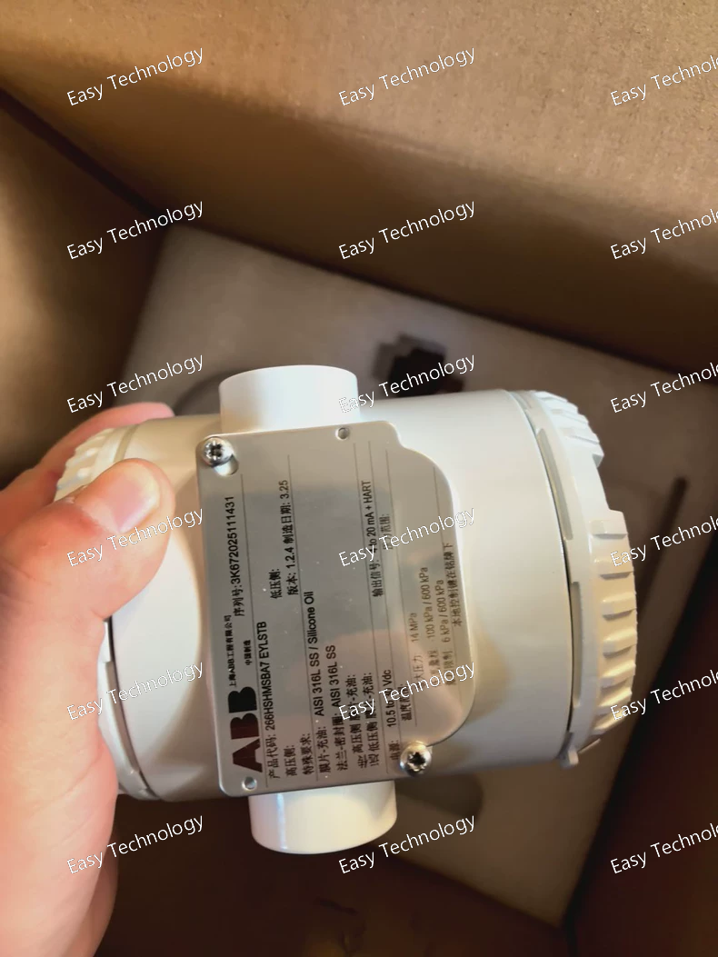
Technical Parameters Parameter Specification Measured Variable Gauge Pressure Range / Span Medium to high range (depends on MS sensor option) Reference Accuracy ±0.06% of span (typical) Turn-down Ratio Up to 100:1 Static Pressure Rating Up to 420 bar (depending on configuration) Overload Capability Full static pressure rating without damage Output Signal 4–20 mA analog + HART communication Power Supply 10.5–45 VDC Wetted Parts Material Stainless Steel (MS) Housing / Enclosure BA7 robust housing suitable for industrial installation Local Display LCD display with Through-The-Glass (TTG) keypad (LS) Electrical Connection Terminal Block (TB) Environmental Rating IP66/67 (depending on installation) Process Temperature –40 to +120 °C (depending on fill fluid and configuration) Ambient Temperature –40 to +85 °C Certifications Hazardous area certified (EY), HART compatible
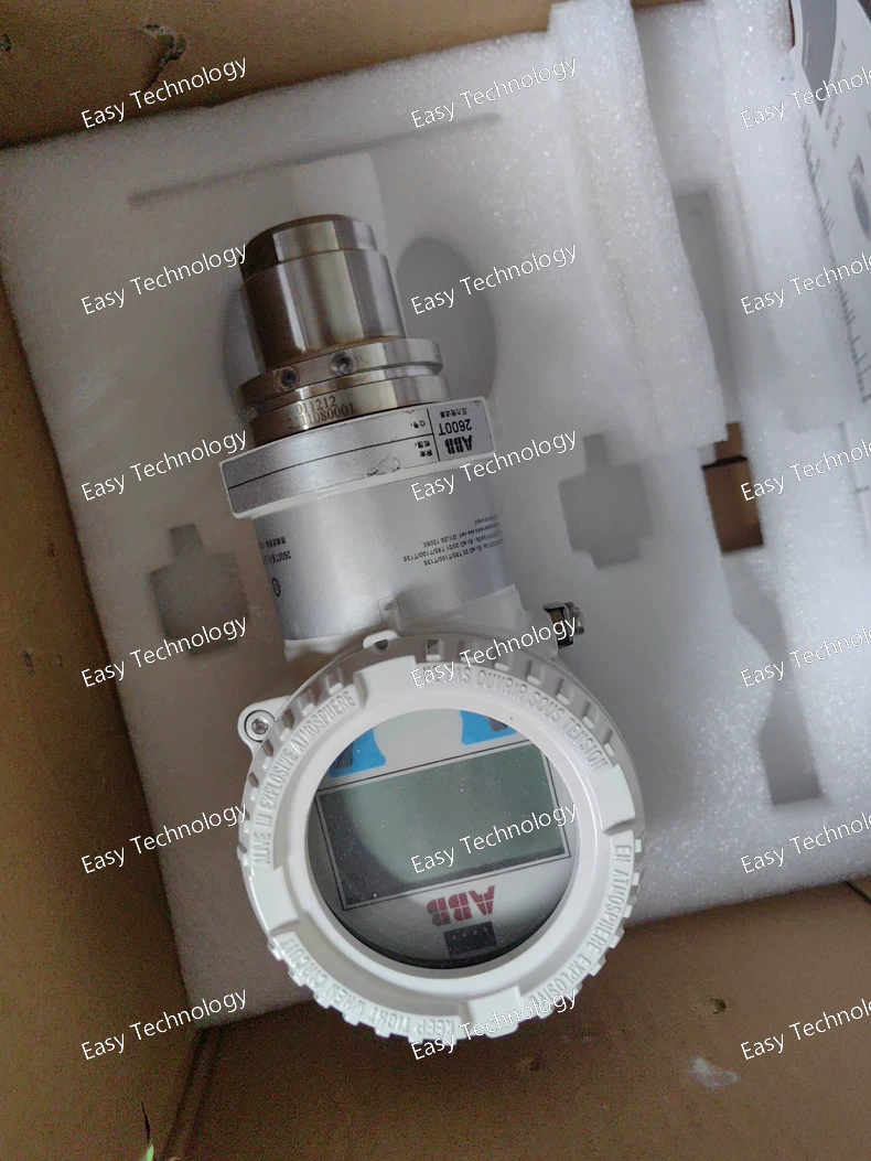
Technical Parameters Measurement Measured variable: Differential Pressure (DP) Range code: P (dependent on order code; typically high-range DP) Span limits: Up to 52 bar (750 psi) DP depending on sensor code Turn-down ratio: Up to 100:1 Static pressure rating: Up to 420 bar (6000 psi) depending on process connection Overload capability: Both sides withstand full static pressure rating Performance Reference accuracy: Up to ±0.025% of calibrated span Stability: ±0.1% of URL for 10 years Response time: As fast as 100 ms (depends on damping) Output & Electronics Output signal: 4–20 mA analog + HART 7 Digital protocol: HART 7 Power supply: 10.5–45 VDC (dependent on load) Construction / Materials Wetted parts: Stainless steel (SS) Diaphragm material: Stainless steel or equivalent based on HS/HSH high-range configuration Body / sensor housing: AISI 316 stainless steel Process & Environmental Process temperature: –40 to +120 °C (depending on fill fluid and options) Ambient temperature: –40 to +85 °C Protection class: IP67 / IP68 depending on housing Explosion-proof options: EYL – Typically indicates ATEX / IECEx flameproof or intrinsic safety certification
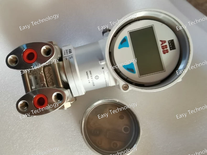
Performance Specifications (General for 266DSH) Base accuracy: from ±0.06% of calibrated span (depending on sensor/span configuration) Span limits (differential pressure span options): from as low as 0.05 kPa up to 16,000 kPa depending on sensor option — wide flexibility. Turn-down ratio: up to 100:1 (depending on configuration) Static (line) pressure capability: depending on sensor and static-pressure rating; typical static pressure ratings up to tens of MPa for standard static versions — able to withstand high line pressures even while measuring small differential pressures. Over-/Proof pressure capability: Designed to handle high static pressures safely; in standard static versions the transmitter can be exposed to high overpressure without leaking (static pressure rating varies with sensor / materials). Output / Communication Options: Standard 4–20 mA + HART digital communication. Other fieldbus/digital protocols (e.g. FOUNDATION Fieldbus, PROFIBUS PA) are available depending on ordering code. Configuration & Display: Configuration can be done locally via integrated LCD + keypad (TTG) or via external HART / fieldbus communicator or PC. Diagnostics & Safety: Built-in diagnostics including Plugged-Impulse-Line Detection (PILD). Suitable for SIL2 / SIL3 safety-critical applications. Environmental / Robustness: Suitable for harsh process / ambient conditions; designed for industrial environments with vibration, variable temperature, possibly dusty or wet atmospheres; meets relevant industrial standards for electromagnetic compatibility, ingress protection (dust/water), shock & vibration, static-pressure endurance, etc. Units / Output Scaling: Supports wide range of engineering units for pressure differential (kPa, Pa, MPa, bar, psi, inH₂O, ftH₂O, mmHg, atm, etc.) depending on configuration and communication protocol. Flexible Configuration: The transmitter is factory-calibrated to customer-specified span / range; but all parameters (Lower Range Limit, Upper Range Limit, engineering units, damping, tag name, static pressure rating, flange type/material, O-rings, vent/drain valve, optional display, certificates etc.) can be configured later via communicator or PC.
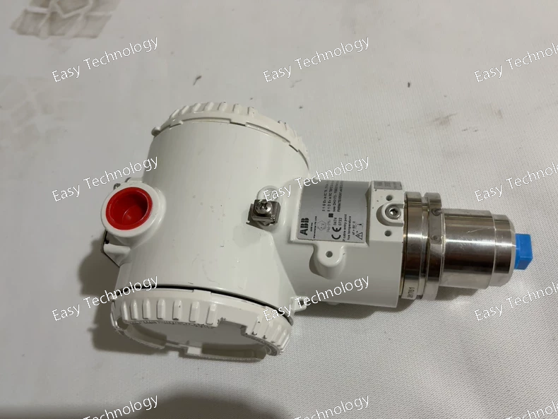
Technical Parameters General Type: Gauge pressure transmitter Model: 266HSH Configuration code: MSBA1 Application: Measurement of liquid, gas, or steam pressure Design: High-overload capability, long-term stability, suitable for harsh industrial environments Measurement Range Span code M: 6 to 600 kPa Turn-down ratio: Up to 100:1 Reference accuracy: ±0.06% of calibrated span Long-term stability: Typically ±0.15% of URL over 10 years Wetted Parts Code S: Diaphragm material: AISI 316L stainless steel Fill fluid: Silicone oil Compliance: NACE compatible Process Connection Code B: Connection type: 1/2-14 NPT female Material: AISI 316L stainless steel Housing / Electrical Code A: Housing material: Aluminum alloy (barrel type) Electrical connection: 1/2-14 NPT Output / Communication Code 1: Signal: 4–20 mA Communication: HART protocol Physical / Environmental Approximate weight: 2.1 kg Suitable for outdoor and industrial environments Resistant to vibration, temperature fluctuation, and overpressure
Technical Parameters General Performance Type: High-overload gauge pressure transmitter Measured media: Liquids, gases, steam Pressure range: From low spans up to 105 MPa (15,225 psi) depending on sensor option Turn-down ratio: Up to 100:1 Reference accuracy: Up to ±0.06% of calibrated span (depending on configuration) Long-term stability: Typically better than ±0.15% of URL over 10 years Output / Communication 4–20 mA with HART (standard) Optional digital protocols depending on configuration (e.g., Modbus, Profibus PA, Foundation Fieldbus, WirelessHART) Local configuration possible through Through-The-Glass (TTG) keypad without opening housing Mechanical / Materials Wetted parts: Stainless steel or other materials depending on option Diaphragm: Stainless steel or Hastelloy (varies by code) Housing: Aluminum alloy or stainless steel (barrel-type body) Typical process connection: 1/2"–14 NPT female or according to option code Display / Interface “LS” option: Integrated LCD display with local push-buttons Supports configuration, calibration, and diagnostics on site Certifications / Safety SIL2 or SIL3 capable (depending on installation), per IEC 61508 Hazardous-area approvals depending on “TB” / “EY” model options Suitable for safety-critical industrial environments Environmental Designed for extreme process and ambient conditions Wide operating temperature range High resistance to overpressure and vibration
Parameters Category Specification Communication KNX TP1 (Twisted Pair) Supply Voltage Via KNX bus (21–32 V DC, SELV) Bus Current Consumption Typically ≤ 15 mA (depends on backlight status) Display High-resolution color TFT touchscreen (main unit) Bedside Panel Backlit physical buttons with engraved/illuminated icons for Light Scene, DND, Make Up Room, Off. Programming Configured entirely via ETS (Engineering Tool Software). The bedside button functions (EZ) are mapped to KNX telegrams within the ETS project. Primary Functions • Full room control via main touchscreen (lighting, blinds, HVAC, etc.) • One-touch control of a master lighting scene via the main LS button. • Hotel-style guest functions via bedside panel: Privacy/DND, Service Request, Room Off. • Customizable graphical interface on the main screen. Protection Rating Front plate: IP20 Ambient Temperature Operation: 0 °C to +45 °C Approvals KNX Certified, CE, RoHS compliant Mounting Flush-mounted (TB), requires a deep mounting box (e.g., 60mm) to accommodate the device depth.
Parameters Category Specification Communication KNX TP1 (Twisted Pair) Supply Voltage Via KNX bus (21–32 V DC, SELV) Bus Current Consumption Max. 15 mA Display High-resolution, colour TFT touchscreen with dynamic graphics capability Programming Exclusively via ETS (Engineering Tool Software), version 5.7 or higher recommended. Core Functions • Centralized room control (lighting, blinds, HVAC) • Customizable user interface with pages, icons, and graphics • Visual feedback and status display • Scene control and scheduling capabilities Protection Rating IP20 (for indoor dry environments) Ambient Temperature Operation: 0 °C to +45 °C Storage: -25 °C to +55 °C Approvals KNX Certified, CE, RoHS compliant Mounting Surface-mounted (A7), designed to be installed on solid walls.
Parameters & Specifications Category Specification Communication KNX TP1 (Twisted Pair) bus system Supply Voltage Via KNX bus (21–32 V DC, SELV) Bus Current Consumption Typically ≤ 10 mA (approx. 170 mW) Display High-resolution colour TFT touchscreen Memory Integrated for storing custom user interfaces, graphics, and icons Programming & Commissioning Configured and programmed with the ETS (Engineering Tool Software), version 5.7 or higher recommended. Primary Functions Lighting control (on/off, dimming, scenes) Blinds/shutter control Room temperature control and display Status monitoring (windows, alarms) Navigation through custom pages Integration of third-party system status Protection Rating IP20 (for indoor use only) Ambient Temperature Operation: 0 °C to +45 °C Storage: -25 °C to +70 °C Approvals & Standards KNX Certified, CE, RoHS compliant
 TEL: Grace +86 13600179521
  Mail: info@hongkongeasy.com jilineasyyi@outlook.com
 Q Q:615739355
 ADDRESS:Unit 12, 20th Floor, Good View Commercial Centre, 2-16 Garden Street, Mong Kok, Hong Kong
 whats app


