
Industrial Controller
All product are in stock,guaranteed delivery within 3-7 days.


PRODUCT
PICTURE
BRAND
DESCRIBE
STOCK
DOWNLOAD
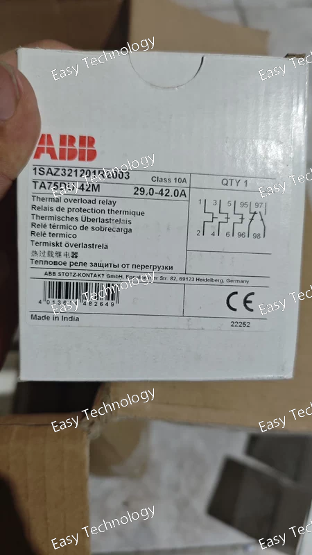
Key Technical Parameters General & Protection Product / Model: ABB TA75DU‑42M Thermal Overload Relay Part Number: 1SAZ321201R2003 Device Type: Thermal overload protection relay Application: Protection of three‑phase motors from overload and phase loss Mounting: Mounted directly onto compatible contactors (e.g., AX50, AX65, AX80 series) Trip Class: Class 10A (standard thermal trip characteristic) Reset: Manual or automatic reset configurable Current & Settings Adjustable Current Setting Range: 29 – 42 A Rated Operational Current (Ie): 42 A Temperature Compensation: Yes (helps maintain consistent protection across ambient temps) Phase Protection: Detects phase failure and imbalance Contacts & Signals Auxiliary Contacts: 1 Normally Closed (NC) – trip contact 1 Normally Open (NO) – signal/indication contact Signal/Control Contact Ratings: Suitable for control logic and panel indication circuits Electrical & Connection Rated Insulation Voltage: Up to 690 V AC (main circuit) Rated Operational Voltage (Main Circuit): Up to 690 V AC Auxiliary Contact Ratings: Typical small control loads (e.g., up to a few amps at common control voltages) Terminal Type: Screw terminals for main and auxiliary circuits Suitable Contactor Types: AX50, AX65, AX80 series contactors Physical & Environmental Poles: 3‑pole (for three‑phase circuits) Degree of Protection: IP20 (housing terminals protected) Ambient Operating Temperature Range: ~‑25 °C to +55 °C Storage Temperature Range: ~‑40 °C to +70 °C Product Size (approx): Width ~54 mm × Height ~90 mm × Depth ~111 mm Net Weight: ~0.33 kg Features & Functions Trip‑Free Mechanism: Ensures the relay remains open once tripped until reset Stop and Test Buttons: Allows simulation and stopping for testing and safety verification Reliable Electromechanical Protection: Uses bimetal elements for thermal detection Temperature Compensation: Maintains accurate trip over temperature variations
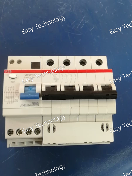
Key Technical Parameters General & Function Product / Model: ABB F204 AC‑80/0.03 RCCB Device Type: Residual Current Circuit Breaker (Leakage Current Protector) Series: F200 series (AC type residual current) Number of Poles: 4 (3 phases + neutral) Mounting Type: DIN‑rail Electrical Ratings Rated Current (In): 80 A Rated Operational Voltage: 230/400 V AC (three‑phase) Rated Insulation Voltage (Ui): 500 V Rated Residual (Leakage) Current: 30 mA (0.03 A) — trips on earth leakage Leakage Current Type: AC (responds to sinusoidal AC leakage) Rated Frequency: 50 Hz / 60 Hz Rated Conditional Short‑Circuit Current (Inc): ~10 kA Rated Service Short‑Circuit Breaking Capacity (Ics): ~1 kA Rated Impulse Withstand Voltage (Uimp): ~4 kV Performance & Endurance Electrical Endurance: ~10,000 switching cycles Power Loss: Approx. 5.3 W per pole under rated conditions Operating Ambient Temperature: –25 °C to +55 °C Pollution Degree: 2 (standard industrial environments) Mechanical & Connections Terminal Type: Screw terminals for line and load connections Connectable Conductor Sizes: Typical solid/flexible conductor ranges up to ~35 mm² Neutral Position: Right side (standard) Width: 4 modular units (fits standard DIN rail panel space) Applications Personnel Protection: Protects against electric shock from ground faults Equipment Safety: Reduces risk of fire or damage from earth leakage currents Distribution Boards: Used at the beginning of circuits feeding sub‑circuits Residential, Commercial & Industrial Installations: Where earth leakage protection is required
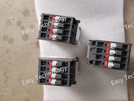
Key Technical Parameters General & Electrical Ratings Product / Model: ABB AL40‑30‑10 24VDC Contactors Part Number: Typically 1SBL323001R8110 Device Type: AC/DC Power Contactor No. of Poles: 3 (three‑phase main contacts) Auxiliary Contacts: 1 normally open (1 NO) Control/Coil Voltage: 24 V DC Control Circuit Type: DC operated with solid core magnet Current & Power Ratings Rated Operational Current (AC‑3): ~37 A at 415 V AC (typical duty) Rated Operational Current (AC‑1): ~60 A at 690 V AC (free‐air, 40 °C) Rated Insulation Voltage (Ui): ~1000 V AC Rated Breaking Capacity (AC‑3): ~8 × Ie Rated Making Capacity (AC‑3): ~10 × Ie Rated Operational Power (AC‑3): ~18.5 kW at ~380–400 V AC ~22 kW at ~440–500 V AC ~18.5 kW at ~690 V AC DC Load Capability (DC‑13): up to ~6 A at 24 V DC Mechanical & Switching Switching Frequencies: AC‑1: ~600 cycles/hour AC‑3: ~1200 cycles/hour AC‑2/AC‑4: ~300 cycles/hour Conventional Free‑Air Thermal Current (Ith): ~16 A (IEC rating for contact endurance) Operate / Release Times: Typical coil pull‑in and release in the tens of milliseconds range Control & Connections Coil Consumption: Low consumption DC coil suitable for driving directly from PLC or control circuitry Terminal Type: Screw terminals for main and control circuits Polarity: Respect polarity on DC coil terminals (A1+ and A2‑) Physical & Environmental Block‑Type Design: Compact, robust industrial contactor Ambient Operating Temperature: ~‑25 °C to +55 °C Mounting: Panel or DIN‑rail compatible in modular control panels Degree of Protection: Standard industrial housing (IP20 terminals) Applications Three‑phase motor starting and stopping in control panels Power circuit switching and isolation in industrial and commercial systems DC control systems such as PLC outputs and automated logic panels Control of lighting, heating, capacitor banks, and other loads up to the rated current
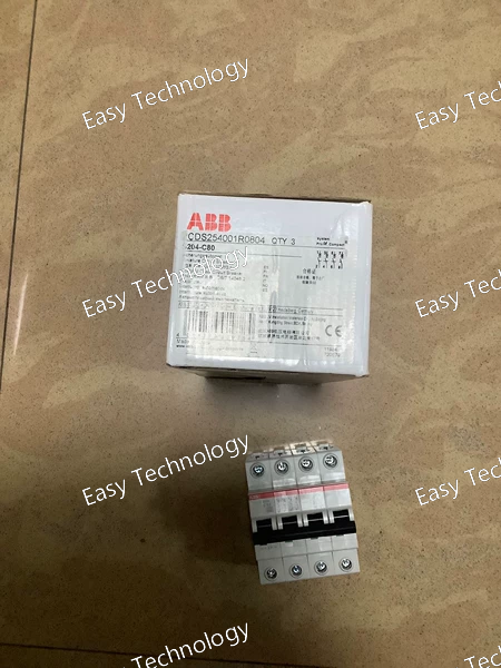
Key Technical Parameters General & Electrical Ratings Product / Model: ABB S204‑C80 Miniature Circuit Breaker Number of Poles: 4 (four‑pole) Rated Current (In): 80 A Tripping Characteristic: Type C (for moderate inrush current) Rated Operational Voltage: 400 V AC (typical three‑phase systems) Operational Frequency: 50 Hz / 60 Hz Rated Insulation Voltage (Ui): 440 V Rated Impulse Withstand Voltage (Uimp): ~4 kV (higher at altitude) Rated Short‑Circuit Breaking Capacity (Icu): • ~6 kA at 400 V AC • Up to ~20 kA at 230 V AC (conditional) Service Short‑Circuit Breaking Capacity (Ics): ~6 kA at 400 V AC Current Limiting Class: Class 3 (limits let‑through energy during fault) Overvoltage Category: Category III Rated Voltage Type: AC Mechanical & Installation Mounting: DIN‑rail (TH35) Actuator Type: Toggle handle with ON/OFF marking Terminal Type: Screw terminals (failsafe cylinder‑lift) Connectable Conductor Size: Solid: ~2.5–50 mm² Stranded: ~2.5–50 mm² Flexible: ~4–35 mm² Tightening Torque: ~3 N·m Mechanical Endurance: ~20,000 operations Electrical Endurance: ~10,000 AC cycles Width: ~4 modular units (~70 mm) Depth: ~69 mm Height: ~88 mm Degree of Protection: IP20 (housing, terminals) / IP40 with enclosure Environmental Ambient Operating Temperature: ~‑25 °C to +55 °C Storage Temperature: ~‑40 °C to +70 °C Applications Overload & Short‑Circuit Protection: protects branch circuits and feeders. Three‑Phase Power Distribution: used in industrial and commercial electrical panels. Load Types: suitable for circuits with moderate inrush (lighting, small motors, general loads). Compact Modular Breaker: fits standard DIN modular panels.
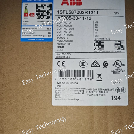
Key Technical Parameters General & Electrical Ratings Product / Model: ABB AF305‑30‑11‑13 Type: Three‑pole magnetic contactor (non‑reversing) Poles (Main): 3 normally open (3 NO) Auxiliary Contacts: 1 normally open + 1 normally closed (1 NO + 1 NC) Control (Coil) Voltage: 100 – 250 V AC/DC (wide range for both AC and DC control circuits) Rated Insulation Voltage (Ui): Up to 1000 V (IEC) / 600 V (UL) Rated Frequency: 50 Hz / 60 Hz Current & Power Performance Conventional Free‑Air Thermal Current (Ith): Up to 500 A Rated Operational Current AC‑1 (Ie): Typical ~375 A at 690 V (varies with temperature) Rated Operational Current AC‑3 (Ie): ~305 A at 415 V Rated Operational Power (AC‑3): ~160 kW at 380–440 V Higher power capability depending on system voltage rating General Use Rating (UL/CSA): ~400 A at 600 V AC Horsepower Ratings: ~125 hp at 220–240 V AC ~250 hp at 440–480 V AC ~300 hp at 550–600 V AC Switching & Protection Rated Making Capacity (AC‑3): ~10 × Ie Rated Breaking Capacity (AC‑3): ~8 × Ie Impulse Withstand Voltage: ~8 kV Built‑In Surge Suppression: Yes Mechanical & Durability Mechanical Durability: ~5 million operations Maximum Electrical Switching Frequency: ~300 cycles/hour Terminal Type: Main circuit bars and screw terminals Degree of Protection: IP20 for coil/auxiliary terminals, IP00 for main terminals Operating Ambient Temperature: Approx. –25 °C to +50 °C with thermal relay; –40 °C to +70 °C without thermal relay Physical Frame Size: AF305 series Dimensions (approx): ~225 mm (H) × ~140 mm (W) × ~180 mm (D) Weight: ~4.6 kg Applications Motor starters for three‑phase induction motors Power circuit switching in distribution and automation panels Isolation and bypass switching Industrial control systems requiring robust contactors with wide coil voltage flexibility
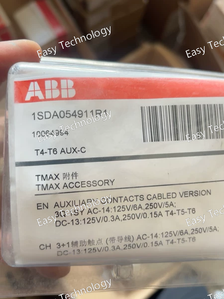
Key Technical Parameters General & Compatibility Product / Model: ABB Auxiliary Contact Block Part Number: 1SDA054911R1 Designed For: Use with ABB Tmax T series MCCBs (T4, T5, T6 frames) Accessory Type: Auxiliary contact block (contact extension / signaling) Voltage Rating: Up to 250 V AC/DC Contact Configuration Total Contacts: 4 changeover contacts 3 changeover contacts for main auxiliary switching 1 changeover contact dedicated for “tripped” indication Contact Type: Changeover (SPDT) style — providing both NO and NC behavior as needed for control logic Usage & Function Status Signaling: Provides remote indication of MCCB position (ON/TRIPPED/OFF) via auxiliary contacts Control Logic: Suitable for use in interlocks, alarms, and safety control circuits Installation: Mounted directly on compatible circuit breaker frames (T4, T5, T6), expanding their auxiliary interface Mechanical & Environmental Mounting Style: Breaker accessory block — attaches to the side of a compatible MCCB Compact Size: Designed not to significantly increase MCCB footprint Indicator Outputs: Multiple changeover outputs allow integration with PLCs, meter trip logic, and alarm systems Typical Applications Remote breaker status monitoring Integration into control panels and switchgear Safety or automation systems requiring breaker feedback Interlocking and alarm circuits driven by breaker state
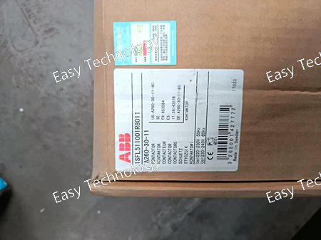
Key Technical Parameters General & Electrical Ratings Product / Model: ABB A260‑30‑11 Contactor Poles (Main): 3 normally open (3 NO) Auxiliary Contacts: 1 normally open (1 NO) + 1 normally closed (1 NC) Control/Coil Voltage: 220–230 V AC (50 Hz) / 230–240 V AC (60 Hz) Rated Operational Voltage (Main Circuit): Up to 690 V AC Rated Frequency: 50 Hz / 60 Hz Current & Power Ratings Thermal Current (Ith): ~400 A (free‑air at 40 °C) Rated Operational Current AC‑1 (Ie): • ~400 A (690 V AC at 40 °C) • ~350 A (690 V AC at 55 °C) • ~290 A (690 V AC at 70 °C) Rated Operational Current AC‑3 (Ie): • ~260 A at 220–240 V AC • ~260 A at 380–400 V AC • ~240 A at 440–500 V AC • ~220 A at 690 V AC Rated Operational Power AC‑3 (Pe): • ~80 kW at 220–240 V AC • ~140 kW at 380–400 V AC • ~180 kW at 500 V AC • ~200 kW at 690 V AC Switching Capacity Rated Making Capacity (AC‑3): ~10 × Ie Rated Breaking Capacity (AC‑3): ~8 × Ie Mechanical & Thermal Operating Durability: Designed for millions of operations Impulse Withstand Voltage: ~8 kV Control‑Circuit Consumption: Typical for industrial contactor coils Connection: Rail or busbar connection for main circuit; screw terminals for control Physical Mounting: Panel or MCC bucket mounting Weight: ~5.4 kg Size: Large industrial contactor class Applications Motor Control: Starting and stopping three‑phase induction motors Power Switching: Switching of heavy industrial loads and distribution panels Control Panels: Integration with overload relays and automation systems Industrial Automation: Suitable for rugged environments in machinery and process control
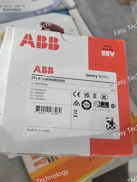
Key Technical Parameters General & Safety Model / Part Number: ABB BSR11 24 VDC Series: Sentry Safety Relays Device Type: Safety relay / expansion relay Supply Voltage: 24 V DC Function: Safety monitoring and expansion of safe outputs Mounting: DIN‑rail (IEC TH35) Protection Degree: IP20 Outputs & Contacts Contact Configuration: 4 normally open (4 NO) relay outputs Output Rating: ~5 A operational current (AC‑15) ~6 A operational current (DC‑13) Contact Type: Mechanical relay outputs with screw terminals Control & Operation Safety Inputs: Designed to connect safety switches such as emergency stops directly into the supply circuit Reset Mode: Selectable reset (e.g., manual/automatic multi‑reset options depending on wiring/configuration) Indicators: LED status indicators for outputs and diagnostics Electrical & Environmental Rated Frequency: DC supply (no AC frequency dependency) Terminal Capacity: Suitable for conductors ~0.2–3.3 mm² (solid/stranded with ferrules) Tightening Torque: ~0.7 N·m (recommended) Operating Temperature Range: Approximately −25 °C to +65 °C Storage Temperature Range: Approximately −40 °C to +70 °C Physical Width: ~22.5 mm Height: ~120 mm Depth: ~120 mm Weight: ~0.19 kg Applications Safety Monitoring: Emergency stops and safety interlocks Output Expansion: Increasing safe output count of safety PLCs/relays Machine Safety Controls: Industrial machinery requiring reliable safety switching Control Panels: Integration in safety control and automation panels
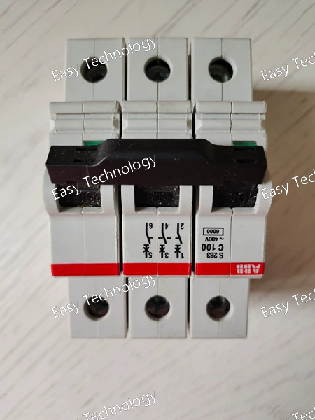
Key Technical Parameters General & Electrical Ratings Product / Model: ABB S203‑C100 Rated Current (In): 100 A Number of Poles: 3 (three‑pole) Tripping Characteristic: Type C (moderate inrush tolerance) Rated Operational Voltage: Up to 400 V AC (max ~440 V) Rated Insulation Voltage (Ui): ~440 V Rated Frequency: 50 Hz / 60 Hz Standards Compliance: IEC/EN 60898‑1, IEC/EN 60947‑2 Degree of Protection: IP20 (housing) Breaking Capacity Rated Ultimate Short‑Circuit Breaking Capacity (Icu): ~10 kA at 230 V AC ~6 kA at 400 V AC Rated Service Short‑Circuit Breaking Capacity (Ics): ~6 kA at 400 V AC Rated Conditional Short‑Circuit Current (Icn): ~6 kA at 400 V AC Performance & Durability Power Loss: ~~29.4 W total (~9.8 W per pole) at rated conditions Electrical Endurance: ~10,000 switching cycles Mechanical Endurance: ~20,000 operations Energy Limiting Class: 3 Operating Temperature: Approx. −25 °C to +55 °C (typical) Mechanical & Installation Mounting Type: DIN‑rail Terminal Type: Screw, bi‑directional or failsafe cylinder‑lift type Connectable Conductors: Solid: ~2.5–50 mm² Flexible: ~4–35 mm² Connecting Capability: Busbar ~16 mm² Width: ~52.5 mm Depth: ~69 mm Height: ~88 mm Weight: ~0.42 kg Applications Protection of branch circuits and feeders in three‑phase systems Used in distribution panels for lighting, motor circuits, and general power distribution Suitable where moderate inrush currents occur (type C curve)
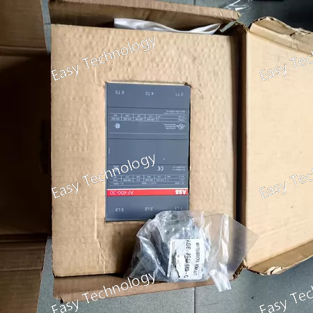
Key Technical Parameters General & Electrical Ratings Product / Model: ABB AF400‑30‑11 3‑pole contactor Number of Poles (Main): 3 normally open (3 NO) Auxiliary Contacts: 1 normally open (1 NO) + 1 normally closed (1 NC) Rated Control (Coil) Voltage: 100 – 250 V AC (50/60 Hz) or 100 – 250 V DC Voltage Type for Actuating: AC/DC wide range Rated Operational Voltage (Main Circuit): Up to 1000 V AC (IEC) / 600 V AC (UL) Rated Insulation Voltage (Ui): 1000 V (IEC) / 600 V (UL) Rated Impulse Withstand Voltage: ~8 kV Current & Power Performance Conventional Free‑Air Thermal Current (Ith): ~600 A Rated Operational Current (AC‑1): 600 A at 400–1000 V AC Rated Operational Current (AC‑3): ~400 A at 415–500 V AC (55 °C) and ~350 A at 690 V AC (55 °C) Rated Operational Power (AC‑3): ~200 kW at 380–400 V AC ~220 kW at 415–440 V AC ~250 kW at 500 V AC ~315 kW at 690 V AC ~220 kW at 1000 V AC (IEC) Switching & Mechanical Rated Making & Breaking Capacity (AC‑3): 10 × Ie (making), 8 × Ie (breaking) Short‑Circuit Protective Devices: gG type fuses up to ~630 A Short‑Time Withstand Current (Icw): various kA levels depending on time and conditions Maximum Electrical Switching Frequency: ~300 cycles/hour (AC‑1 & AC‑3) ~60 cycles/hour (AC‑2 / AC‑4) Mechanical Durability: ~3 million operations Coil & Control Rated Control Circuit Voltage Range: 100–250 V AC/DC Coil Consumption: Holding: ~12 VA at AC, ~4.3 VA at DC Pull‑in: ~955–1100 VA depending on frequency and DC Physical & Environmental Mounting / Terminals: Rail connection or busbar, screw/terminal bar connection Ambient Operating Temperature: ~‑40 °C to +70 °C without derating Altitude Capability: up to ~3000 m without derating Typical Applications Motor starting and control in industrial automation Power distribution switching and isolation Bypass and contactor combinations in large control panels Processes requiring wide‑range coil voltage flexibility
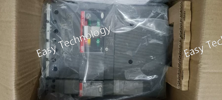
Key Technical Parameters (English) General & Protection Product / Model: ABB XT3N250 TMD250/2500 FF 4P Device Type: Molded Case Circuit Breaker (MCCB) Series: SACE Tmax XT Number of Poles: 4 (three phases + neutral) Trip Unit Type: Thermal‑Magnetic (TMD) Mounting Style: Fixed with front terminals Current & Voltage Ratings Rated Continuous Current (In): 250 A Overload Trip Setting Range: Adjustable (typically a range ending at 250 A) Instantaneous Short‑Circuit Setting: 2500 A Rated Operational Voltage: Up to 690 V AC and 500 V DC Rated Frequency: 50 Hz / 60 Hz Rated Insulation Voltage (Ui): 800 V Rated Impulse Withstand Voltage (Uimp): 8 kV Breaking Capacities Rated Ultimate Short‑Circuit Breaking Capacity (Icu) – AC: ~50 kA at 220–240 V AC ~36 kA at 380–415 V AC ~25 kA at 440–500 V AC ~5 kA at 690 V AC Rated Service Short‑Circuit Breaking Capacity (Ics) – AC: ~50 kA at 220–240 V AC ~36 kA at 380–415 V AC Lower values at higher voltages (e.g., ~18 kA at 440 V AC, ~3.75 kA at 690 V AC) DC Breaking Capability: ~36 kA at 250 V DC (2 poles in series) ~50 kA at 500 V DC (3 poles in series) Performance & Durability Electrical Durability: ~8,000 operating cycles Mechanical Durability: ~25,000 cycles Power Loss per Pole at Rated Conditions: ~17.8 W Terminal Connection: Bolt / front terminals with recommended tightening torque Physical & Environmental Dimensions: Approx. 140 mm × 150 mm × 70 mm (height × width × depth) Weight: ~2 kg Degree of Protection: Standard industrial MCCB housing (typically IP20 on terminals) Operating Environment: Suitable for industrial distribution panels and switchboards Applications Protection of three‑phase power distribution circuits Motor feeder and branch circuit protection
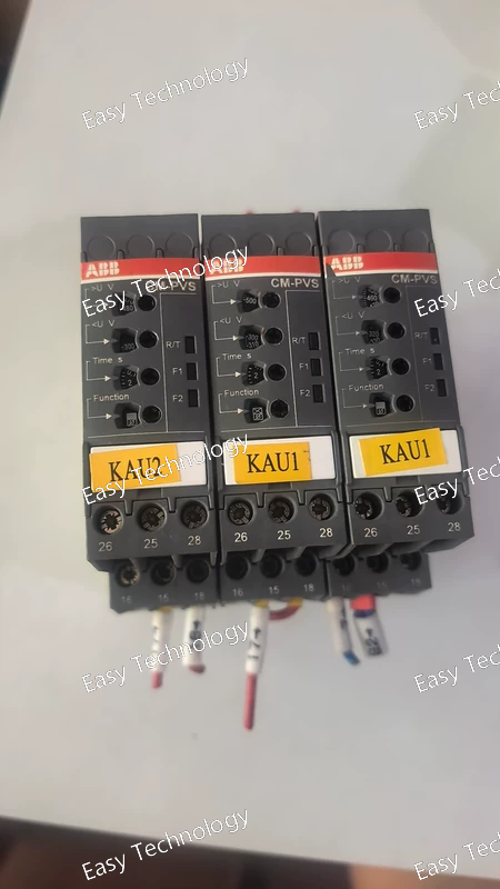
Key Technical Parameters General & Monitoring Product / Model: ABB CM‑PVS.41S Three‑Phase Monitoring Relay Part Number: 1SVR730794R3300 Function: Monitors three‑phase supply for overvoltage, undervoltage, phase failure, and phase sequence faults Supply / Measuring Voltage: 300 V to 500 V AC between phases (L‑L) Measuring Frequency: 50 Hz / 60 Hz Output & Contacts Output Type: 2 change‑over (SPDT) contacts Contact Ratings: Up to 250 V AC at 4 A (typical control load) Timing Startup Delay: ~200 ms Tripping Delay: Adjustable from instantaneous to 30 s Connection & Installation Mounting: DIN‑rail (standard TH35) Terminal Type: Screw terminals with double‑chamber cage connection Environmental Operating Ambient Temperature: –25 °C to +60 °C Storage Temperature: –40 °C to +85 °C Degree of Protection: IP20 on terminals and housing Physical Width: ~22.5 mm Height: ~85.6 mm Depth: ~103.7 mm Weight: ~0.139 kg Typical Applications Phase sequence and phase loss detection for motor protection systems Over/undervoltage monitoring to protect equipment from abnormal supply conditions Industrial control panels used in automation and machine control Signal/alarm interfacing for PLCs or safety circuits upon fault detection
 TEL: Grace +86 13600179521
  Mail: info@hongkongeasy.com jilineasyyi@outlook.com
 Q Q:615739355
 ADDRESS:Unit 12, 20th Floor, Good View Commercial Centre, 2-16 Garden Street, Mong Kok, Hong Kong
 whats app


