
Industrial Controller
All product are in stock,guaranteed delivery within 3-7 days.


PRODUCT
PICTURE
BRAND
DESCRIBE
STOCK
DOWNLOAD
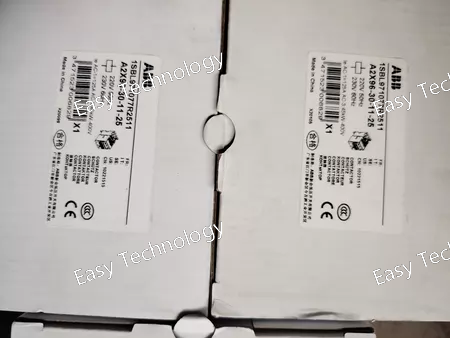
Technical Parameters Electrical Ratings Rated Coil Voltage: 220 V AC / 230 V AC Poles: 3 Main Contacts: 3 normally open (3-NO) Control Circuit: AC coil operated Contact Configuration: 3-Pole main contacts for power switching Operational Performance Suitable for Motor Control and Power Switching: Designed to switch three-phase loads and motor circuits in industrial systems Coil Operating Voltage Range: optimized for 220–230 V AC control Installation: panel or DIN-rail compatible mounting (type-dependent) Mechanical & Connectivity Terminal Type: Screw terminals for main and control wiring Mounting: Suitable for standard electrical enclosures and control panels Design: Compact and rugged industrial construction Environmental & Reliability Operating Conditions: Designed to withstand typical industrial ambient conditions and operating cycles Durability: Constructed for extended operational life in control systems
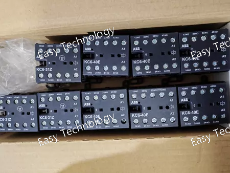
Technical Parameters Control & Electrical Ratings Rated Control Supply Voltage (Uc): 220 – 240 V DC Number of Poles: 4 Rated Operating Current (Ie) AC-15: typically up to 4 A at 220–240 V AC Rated Operating Current (Ie) DC-13: typically up to 0.4 A at 220–240 V DC Minimum Switching Capacity: 17 V / 5 mA Maximum Electrical Switching Frequency: ~600 operations per hour (AC-15 / DC-13) Conventional Free-Air Thermal Current (Ith): ~6 A on auxiliary circuit Mechanical & Installation Mounting Type: DIN-rail or screw mounting Terminal Type: Screw terminals Mechanical Durability: ~10,000,000 operations (typical long life) Mounting Position: Any (positions 1-6) Compact Dimensions: Approx. 52.5 mm (W) × 57.5 mm (H) × 46.5 mm (D) Net Weight: ~0.17 – 0.18 kg Environmental & Protection Operating Ambient Temperature: −25 °C to +55 °C Storage Temperature: −40 °C to +80 °C Degree of Protection: IP20 on terminals Rated Insulation Voltage (Ui): ~690 V (auxiliary circuit) Rated Impulse Withstand Voltage (Uimp): Meets relevant IEC standards Standards & Compliance Conforms to IEC/EN 60947 series for contactor relays Suitable for control circuit applications with DC coil control
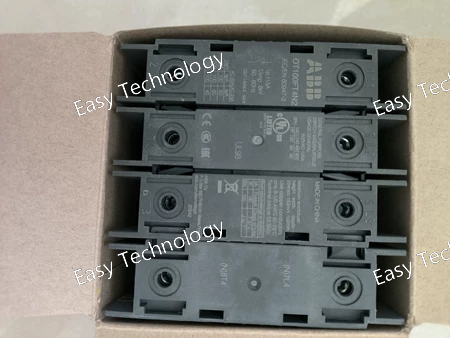
Technical Parameters Electrical Characteristics Number of Poles: 4P Rated Operational Current (Ie): AC-21A: 100 A (380–415 V / 500 V / 690 V) AC-22A: 100 A (380–415 V / 500 V / 690 V) AC-23A: 80 A at 380–415 V 60 A at 500 V 40 A at 690 V Rated Operational Power (AC-23A): 22 kW at 220–240 V 37 kW at 400–415 V 37 kW at 500 V 37 kW at 690 V Rated Operational Voltage: up to 750 V AC Rated Insulation Voltage (Ui): 750 V Rated Impulse Withstand Voltage (Uimp): 8 kV Conventional Free-Air Thermal Current (Ith): 115 A (40 °C) Rated Short-Circuit Making Capacity (Icm): 3.6 kA at 690 V Rated Conditional Short-Circuit Current (Inc): Up to 50 kA with appropriate fuses Mechanical & Installation Operating Type: Front operated Mounting Type: Door mounting Handle / Shaft: Not included Terminal Type: Screw clamp terminals Conductor Size: 10–70 mm² (Cu) Tightening Torque: 6 N·m Mechanical Durability: 20,000 operations Degree of Protection (Front): IP20 Pollution Degree: 3 Standards & Approvals IEC 60947-3 UL 98 CSA C22.2 No.4 Physical Data Approx. Dimensions (W × H × D): 100 × 96 × 70 mm Net Weight: approx. 0.5 kg
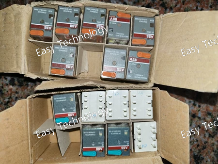
Technical Parameters Parameter Specification Series / Product Type ABB CR-M Series / 2-Pole Auxiliary Contact Block (Snap-on) Order Code CR-M230AC4 Contact Configuration 2 Normally Open (NO) (Two independent, single-pole, normally open contacts). Contact Material Fine silver alloy, suitable for reliable low to medium current switching. Rated Operational Current (Ie) 4 A (at the rated voltage, see below) Utilization Category AC-15: Control of electromagnetic loads (e.g., contactor, relay coils). DC-13: May also be rated for DC loads, but the "AC4" suffix emphasizes AC rating. Rated Thermal Current (Ith) 10 A Switching Capacity At 230V AC: 4 A (for AC-15) At 24V DC: 4 A (for DC-13, if applicable) Rated Insulation Voltage (Ui) 690V AC / 750V DC Mechanical Life Typically 10 million operations or more. Electrical Life At rated load (AC-15): Typically 300,000 operations. Connection Screw terminals for each contact. Terminals are typically marked as A1/A2 for one contact and 13/14 (or similar) for the other. Mounting Snap-on attachment to the rear of compatible CR-M series actuator heads. Multiple contact blocks can be stacked together. Safety Feature Contacts are typically not positively guided (force-guided). For safety-related applications requiring forced contact separation, a different block (e.g., CR-MX series with "D" code) must be selected. Standards Compliance IEC/EN 60947-1, IEC/EN 60947-5-1 Ambient Temperature -25°C to +70°C (Operation) Protection Degree (IP Rating) IP40 (as part of the assembled device in an enclosure)
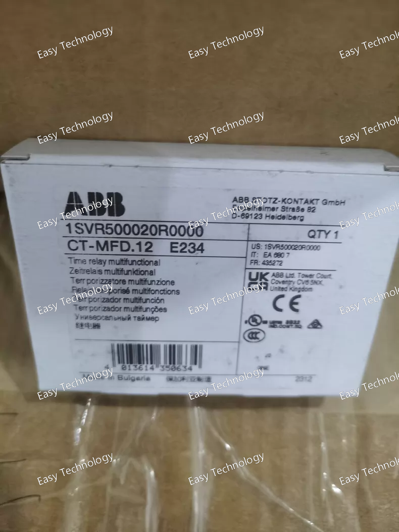
Technical Parameters | Parameter | Specification | | Series / Product Type | ABB MFD Series / Split-Core Current Transformer (CT) | | Order Code | CT-MFD.12 | | Core Type | Split-Core (Clamp-On) | | Rated Primary Current (Ipn) | 100 A | | Rated Secondary Current (Isn) | 5 A | | Transformation Ratio | 100/5 A | | Accuracy Class | Typically Class 1 or 0.5 (for measurement, at rated burden and 50/60 Hz). | | Frequency | 50/60 Hz | | Rated Thermal Short-Time Current (Ith) | Typically 60 x Isn for 1 second (e.g., 300A for 1s). | | Rated Output (Burden) | Typically 5 VA or 2.5 VA (Standard values like 2.5VA, 5VA, 10VA). | | Accuracy Limit Factor (ALF) | Typically 5 (for measurement) or higher (for protection). | | Insulation Voltage | 0.72 kV / 0.75 kV (For low-voltage systems up to 600V AC). | | Aperture (Inner Diameter) | Typically Φ30 mm (Common size for MFD series, allows for cable or small busbar). | | Mounting | Can be mounted via integrated lugs or simply clamped onto the conductor. | | Secondary Connection | Screw terminals for secondary wiring (typically marked S1 and S2). | | Safety Standard | IEC/EN 61869-1, IEC/EN 61869-2 (Replaces older IEC 60044-1) | | Operating Temperature | -25°C to +70°C |
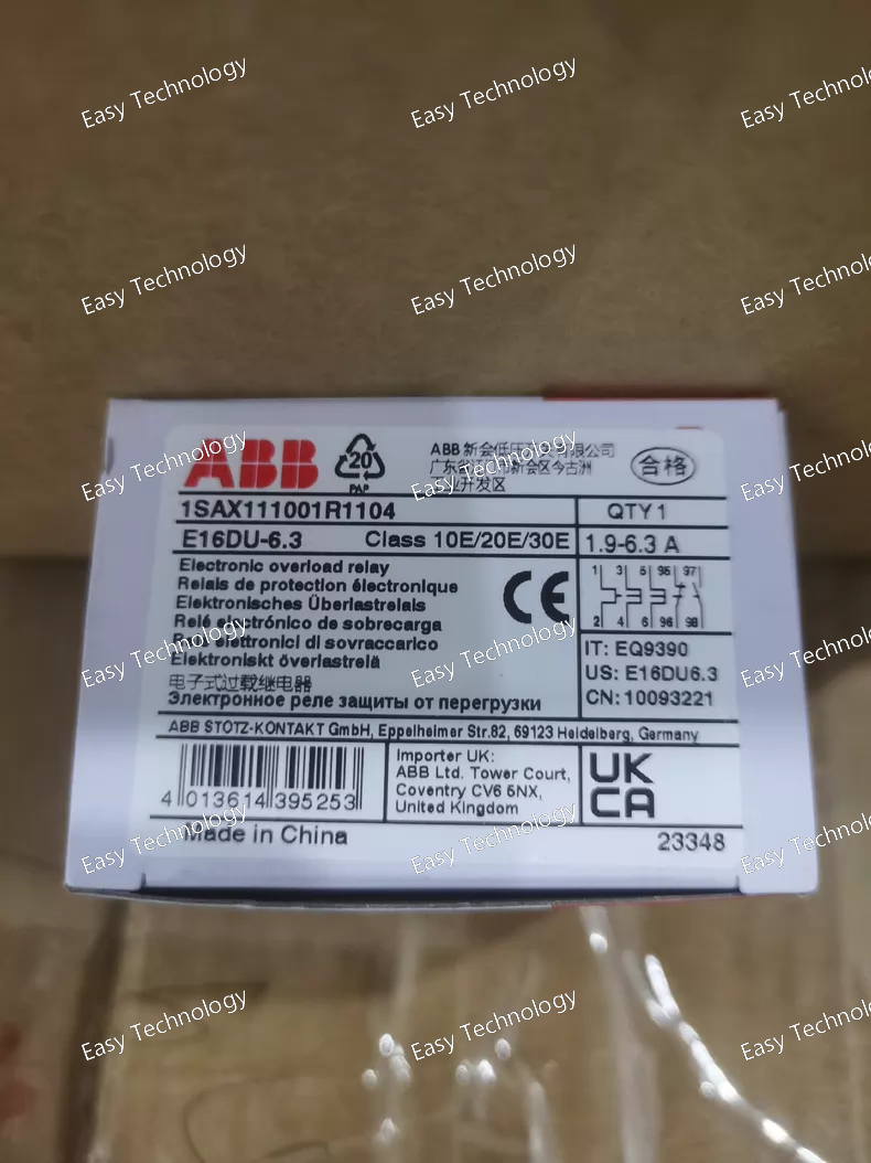
Technical Parameters Parameter Specification Series ABB E16 / DS260 / Form 1a Series Product Type 3-Pole, Manual Motor Starter / Motor Protection Circuit Breaker (MPCB) Order Code E16DU6.3 Number of Poles 3-Pole (3P) Rated Operational Current (Ie) Up to 16A (Frame rating). Thermal Overload Setting Range (Ir) Adjustable: 0.10 - 6.3 A (Continuously adjustable via dial). Trip Class Class 10 (Standard for motor protection). Magnetic Short-Circuit Setting (Im) Fixed, typically at 12 x Ir or a specific high value (e.g., ~100A). Short-Circuit Breaking Capacity (Icu) Typically 6 kA or 10 kA at 400V AC. Rated Operational Voltage (Ue) 690V AC Control Method Manual (ON/OFF handle). No coil for remote operation. Auxiliary Contacts None as standard. Optional auxiliary contact blocks (e.g., 1NO+1NC) can usually be added. Phase Loss Sensitivity Yes (Inherent in the 3-pole thermal design). Ambient Temperature Compensation Yes (integrated). Mounting Snap-on mounting on 35mm DIN Rail. Connection Terminals Screw terminals. Standards Compliance IEC/EN 60947-1, IEC/EN 60947-2, IEC/EN 60947-4-1 (as a combination starter). Motor Power Rating At 400V AC, 3-phase: Approx. 3 kW (4 HP) (Based on 6.3A setting). Ambient Temperature -25°C to +60°C (Operation)
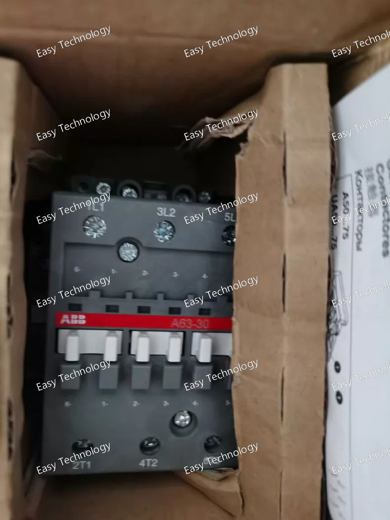
Technical Parameters Parameter Specification Series ABB A-Series (AF Series) Contactor Product Type 3-Pole Electromagnetic Contactor Typical Order Code A63-30-11 (AC220V is often specified separately or implied by -30-) Number of Main Poles 3-Pole (3P) Rated Operational Current (Ie) At AC-3 (Motor Switching): 63 A (at 400V AC) At AC-1 (Resistive): ~ 100 A Rated Thermal Current (Ith) 63 A Rated Operational Power (AC-3) 30 kW (40 HP) at 400V AC Control Coil Voltage 220V AC, 50/60 Hz Power Consumption Pick-up (Inrush): ~ 70 VA Holding (Sealed): ~ 8 VA Auxiliary Contacts (Standard) 1 NO + 1 NC (Changeover configuration). Rated: Typically 600V AC, 10A. Mechanical Life 10 - 30 million operations. Electrical Life At AC-3: 1 - 3 million operations. At AC-1: Up to 10 million operations. Mounting Snap-on mounting on 35mm DIN Rail or screw mounting. Connection Main Terminals: Screw/clamp terminals for 1-50 mm² cables. Coil/Auxiliary Terminals: Screw terminals. Standards Compliance IEC/EN 60947-1, IEC/EN 60947-4-1, UL 508, CSA C22.2 No. 14. Ambient Temperature -25°C to +60°C (Operation, with derating above 55°C) Protection Degree (IP Rating) IP00 (component), requires an enclosure for IP20 or higher.
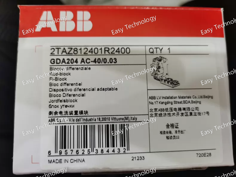
Technical Parameters Parameter Specification Series ABB GDA Series (Modular RCDs for DBs) Product Type 4-Pole (3P+N) Residual Current Device (RCD) Module, Type AC Full Order Code GDA204 AC-40/0.03 Number of Poles 4-Pole (3P + N) Rated Current (In) 40 A (This is the maximum continuous current it can carry. It does not provide overcurrent protection). Rated Residual Operating Current (IΔn) 30 mA (0.03 A) Residual Current Type Type AC (for sinusoidal alternating residual currents) Rated Operational Voltage (Ue) 400V AC (3P+N) Rated Insulation Voltage (Ui) 500V AC Rated Short-Circuit Withstand Capacity Typically 10 kA (IEC/EN 61008) – its ability to withstand a fault current without damage when protected by an upstream device. Trip Time at IΔn ≤ 0.3 seconds Trip Time at 5x IΔn (150 mA) ≤ 0.04 seconds Utilization Category AC (for AC circuits only) Mounting DIN Rail (35mm) mounting. Designed for integration into distribution boards with integrated neutral busbar. Connection Phase Terminals: Screw terminals for connecting the three phase conductors. Neutral Connection: Typically via an integrated neutral busbar clamp that grips the main neutral busbar running through the panel. Module Width 4 modules (72mm) or wider, depending on design. Test Button Yes (usually yellow), for periodic functional testing. Mechanical Indicating Handle Shows ON/OFF/I (tripped) status. Standards Compliance IEC/EN 61008-1 (Primary standard for RCCBs without integral overcurrent protection) Ambient Temperature -25°C to +60°C (Operation)
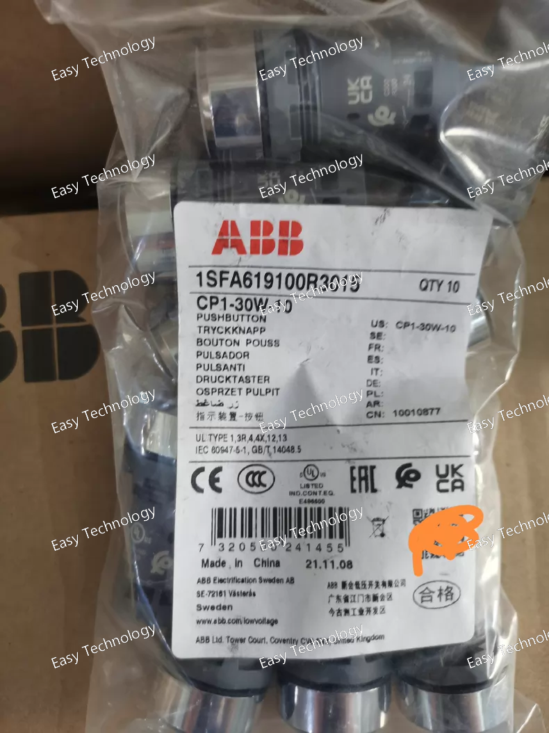
Technical Parameters Parameter Specification Series / Product Type ABB CP1 Series / Single-Output DIN-Rail Switching Power Supply Order Code CP1-30W-10 Input Voltage (AC) 85 - 264 V AC (Wide Range, 47-63 Hz) Input Current Approx. 0.7 A at 115V AC; 0.35 A at 230V AC Output Single Output Output Voltage 24 V DC Rated Output Power 30 W Rated Output Current 1.25 A (at 24V) Output Voltage Adjustment Typically ±10% (e.g., 21.6 - 26.4V) via potentiometer. Ripple & Noise Typically < 150 mVp-p Efficiency Typically > 85% Load Regulation Typically < ±1% Line Regulation Typically < ±1% Overload Protection Constant Current Limiting, Auto-Recovery. Short-Circuit Protection Yes, Hiccup mode, Auto-Recovery. Overvoltage Protection Yes (typically at 135-150% of Vo). Ambient Temperature -25°C to +70°C (Operation with derating above 60°C) Cooling Natural convection (fanless). Protection Class / IP Rating IP20 (for installation inside an enclosure). Mounting DIN Rail (35mm) mounting. Connection Screw Terminals for input (L, N, PE) and output (V+, V-, PE). Status Indicator Green LED for "Power On". Standards Compliance IEC/EN 61558-2-16, IEC/EN 60950-1, UL 508, CE marked. Mean Time Between Failures (MTBF) Typically > 300,000 hours (per MIL-HDBK-217F).
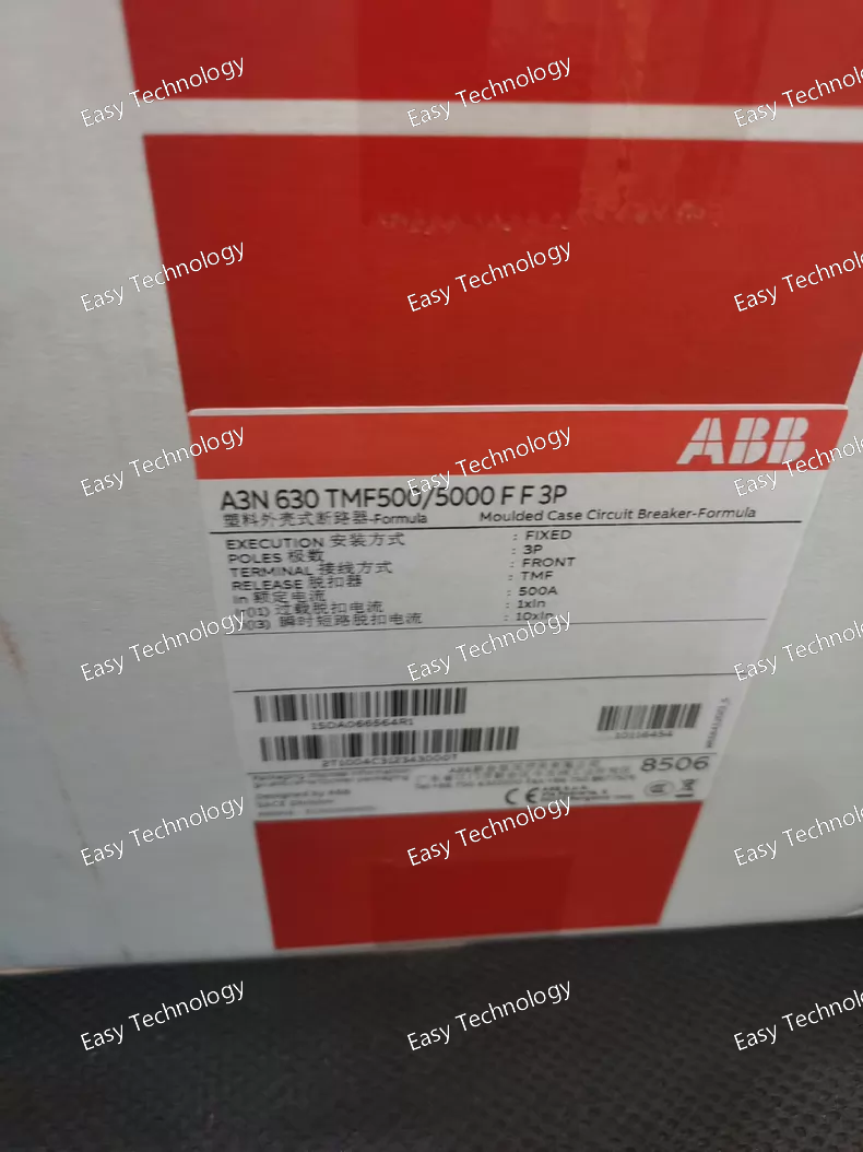
Technical Parameters Parameter Specification Series / Product Type ABB Emax 2 Series / Fixed-Mounting Air Circuit Breaker (ACB) Full Order Code A3N630 TMF500/5000 FF 3P Frame Size / Rated Current (In) E2 / 630 A (Rated continuous current) Number of Poles 3-Pole (3P) Trip Unit Electronic Trip Unit (ETU) - Micrologic F (TMF) Current Sensor (CT) Ratio 5000/500 A (Primary/Secondary) Protection Functions (FF) L-S-I-G • L - Long-time Overload Protection (adjustable Ir, tr) • S - Short-time Short-Circuit Protection (adjustable Isd, tsd) • I - Instantaneous Short-Circuit Protection (adjustable Ii) • G - Ground-Fault Protection (adjustable Ig, tg) Rated Operational Voltage (Ue) 690V AC Rated Insulation Voltage (Ui) 1000V AC Rated Ultimate Short-Circuit Breaking Capacity (Icu) Up to 85 kA at 415V AC (for E2 frame, exact value depends on certification). Rated Service Short-Circuit Breaking Capacity (Ics) Up to 100% of Icu (e.g., 85 kA). Mechanical Life 20,000 operations Electrical Life 5,000 operations at In Communication Capability The TMF unit typically has a built-in communication port (e.g., for connection to an Ekip Com module for communication protocols like Modbus). Mounting Fixed Mounting (for panel assembly). Connection Front and/or rear connection for busbars or cables. Standards Compliance IEC/EN 60947-1, IEC/EN 60947-2 Ambient Temperature -25°C to +70°C (Operation)
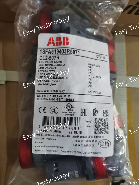
Technical Parameters Parameter Specification Series ABB CL / HomeLine / DS200 Series Product Type 2-Pole (1P+N) RCBO with Overcurrent & Residual Current Protection Order Code CL2-507R Number of Poles 2-Pole (1P+N) – Both phase and neutral are switched, but only the phase pole has overcurrent protection. Rated Current (In) 16 Amperes (The standard current rating associated with the "CL2-5" base model. Other ratings like 10A, 20A, etc., have different suffixes). Tripping Characteristic C-Curve Rated Residual Operating Current (IΔn) 30 mA (0.03 A) Residual Current Type Type AC (for sinusoidal alternating residual currents) Rated Short-Circuit Breaking Capacity (Icn) 10 kA (at 230/400V AC) Rated Operational Voltage (Ue) 230V AC (Single-Phase) Rated Insulation Voltage (Ui) 400V AC Trip Time at IΔn ≤ 0.3 seconds Trip Time at 5x IΔn (150 mA) ≤ 0.04 seconds Test Button Yes (typically yellow), for periodic testing of the RCD function. Mounting DIN Rail (35mm) mounting. Terminals Screw terminals suitable for solid and stranded conductors. Module Width 2 modules (36mm). Standards Compliance IEC/EN 61009-1 (Primary standard for RCBOs) Ambient Temperature -25°C to +60°C (Operation)
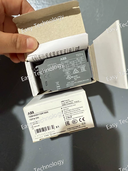
Technical Parameters Parameter Specification Series ABB TEF Series (Electronic RCCB) Product Type 4-Pole (3P+N) Electronic Residual Current Circuit Breaker Order Code (Base) TEF4-ON (Note: The complete order code includes the sensitivity rating, e.g., TEF4-ON/0.03 for 30mA). Number of Poles 4-Pole (3P + N) Rated Residual Operating Current (IΔn) Selectable: 0.03 A (30mA), 0.1 A (100mA), 0.3 A (300mA) (Specified in the full order code). Residual Current Type Likely Type AC (for sinusoidal AC residual currents) as standard. Other types (A, F) may be available in the series. Rated Current (In) Common frame sizes: 25A, 40A, 63A, 80A, 100A. (The "ON" may correlate with a specific current rating; the full code or label is needed). Rated Operational Voltage (Ue) 400V AC (3P+N) Rated Insulation Voltage (Ui) 500V AC Rated Short-Circuit Making & Breaking Capacity (Icm/Icn) Typically 6 kA or 10 kA (according to IEC/EN 61008/9). Trip Time at IΔn ≤ 0.3 seconds Trip Time at 5x IΔn ≤ 0.04 seconds Auxiliary Power Line-powered (electronic) – derives operating power from the monitored circuit. Test Button Yes, for periodic functional testing. Mounting DIN Rail (35mm) mounting. Terminals Screw terminals suitable for both solid and stranded conductors. Standards Compliance IEC/EN 61008-1 (Core standard for RCCBs) Ambient Temperature -25°C to +60°C (Operation)
 TEL: Grace +86 13600179521
  Mail: info@hongkongeasy.com jilineasyyi@outlook.com
 Q Q:615739355
 ADDRESS:Unit 12, 20th Floor, Good View Commercial Centre, 2-16 Garden Street, Mong Kok, Hong Kong
 whats app


