
Industrial Controller
All product are in stock,guaranteed delivery within 3-7 days.


PRODUCT
PICTURE
BRAND
DESCRIBE
STOCK
DOWNLOAD
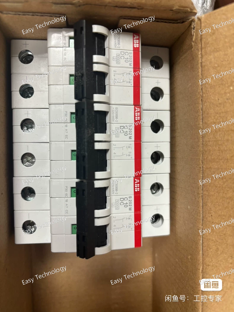
Technical Parameters Specification Value / Description Product Type Miniature Circuit Breaker (MCB) Model S203M‑C10 Poles 3 poles (3P) Rated Current (In) 10 A Rated Operational Voltage 230/400 V AC (Three‑phase) Rated Insulation Voltage (Ui) 440 V AC Rated Operational Voltage (Ue) 400 V AC Rated Short‑Circuit Breaking Capacity (Icn) 10 kA at 400 V AC Rated Ultimate Short‑Circuit Breaking Capacity (Icu) Up to 25 kA at 230 V AC Tripping Curve Type C (magnetic‑thermal trip) Trip Mechanism Thermal for overload, magnetic for short‑circuit Frequency 50 Hz / 60 Hz Connections Screw terminals with cylinder‑lift clamp Mounting DIN‑rail (TH35) Terminal Capacity Flex: 0.75–25 mm²; Rigid: 0.75–35 mm² Power Loss ~6.3 W total (2.1 W per pole) Operating Ambient Temp –25 °C to +55 °C Degree of Protection IP20 (terminal area); IP40 with enclosure Mechanical Endurance ~20,000 cycles Electrical Endurance ~20,000 AC cycles
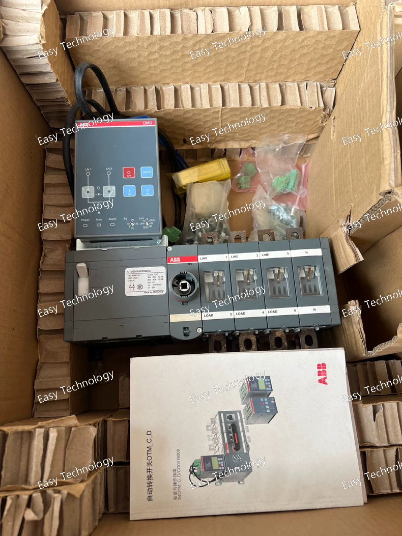
Technical Parameters Specification Typical Value / Description Product Type Motorized Automatic Transfer Switch (ATS) / Change‑Over Switch Model OTM250E4C3D380C Number of Poles 4 poles (three phases + neutral) Rated Operational Current 250 A Rated Insulation Voltage (Ui) ~1000 V AC Impulse Withstand Voltage (Uimp) ~12 kV Rated Operational Voltage Up to ~1000 V AC for main circuit Control / Motor Supply Voltage 380 V AC Rated Short‑Time Withstand Current ~8 kA for 1 s Rated Operational Power (AC‑23A) ≈140 kW at 400 V AC (higher ratings at elevated voltages) Operating Modes Automatic motorized change‑over and manual handle override Mechanical Interlock Yes — prevents simultaneous source connection Handle / Operation Type Direct mounted handle for manual operation Mounting / Installation Panel or enclosure mount Typical Application Automatic transfer between mains and backup generator in industrial and commercial power systems
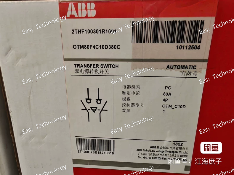
Technical Parameters Specification Typical Value / Description Product Type Motorized Automatic Transfer Switch / Change‑over Switch Model OTM80F4C10D380C Number of Poles 4 poles (3 phases + neutral) Rated Operational Current 80 A Rated Operational Voltage Designed for low‑voltage three‑phase systems (e.g., ~380–415 V AC) Rated Insulation Voltage (Ui) Approx. up to 800–1000 V AC Impulse Withstand Voltage (Uimp) Several kilovolts (device withstands typical surge conditions) Control / Motor Supply Voltage 380 V AC (indicated by suffix) Transition Type Open transition change‑over Operating Modes Automatic (motorized remote) and Manual (handle) Mechanical Interlock Yes — prevents simultaneous connection of both sources Mounting Panel or enclosure mount Typical Application Automatic load transfer between utility and backup power sources in commercial and industrial power systems
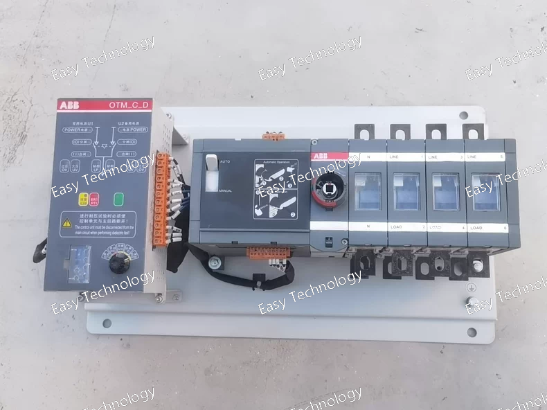
Technical Parameters Specification Typical Value / Description Product Type Motorized Automatic Transfer Switch / Change‑Over Switch Model OTM200E4C10D380C Number of Poles 4 poles (three phases + neutral) Rated Operational Current 200 A Rated Operational Voltage Designed for three‑phase low‑voltage systems (typically up to ~690 V AC) Rated Insulation Voltage (Ui) ~800–1000 V AC Impulse Withstand Voltage (Uimp) Several kilovolts (device withstands typical surge conditions) Control / Motor Supply Voltage 380 V AC (indicated by 380C suffix) Transition Type Open transition change‑over Operating Modes Automatic (motorized) and Manual (handle) Mechanical Interlock Yes — prevents simultaneous connection of both sources Mounting Panel or enclosure mount Typical Application Automatic load transfer between utility mains and backup gensets in industrial and commercial power systems
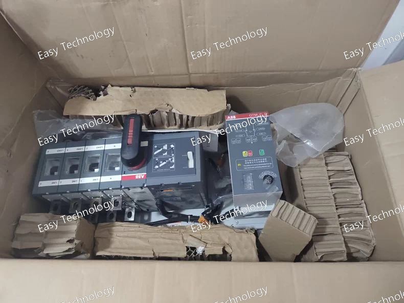
Technical Parameters Specification Typical Value / Description Product Type Motorized Automatic Transfer Switch / Change‑Over Switch Model OTM400E4C11D380C Number of Poles 4 poles (three phases + neutral) Rated Operational Current 400 A Rated Insulation Voltage (Ui) 1000 V AC Impulse Withstand Voltage (Uimp) 12 kV Rated Operational Voltage Up to 1000 V AC Rated Short‑Time Withstand Current ~15 kA for 1 s Rated Operational Power (AC‑23A) Approx. 220 kW @ 400 V; higher at elevated voltages Control / Motor Supply Voltage 380 V AC (motor operator supply) Transition Type Open transition change‑over Operating Modes Automatic motorized and manual handle operation Mechanical Interlock Yes — prevents simultaneous source connection Mounting Panel or enclosure mount Typical Use Automatic transfer between utility mains and backup generator in three‑phase distribution systems
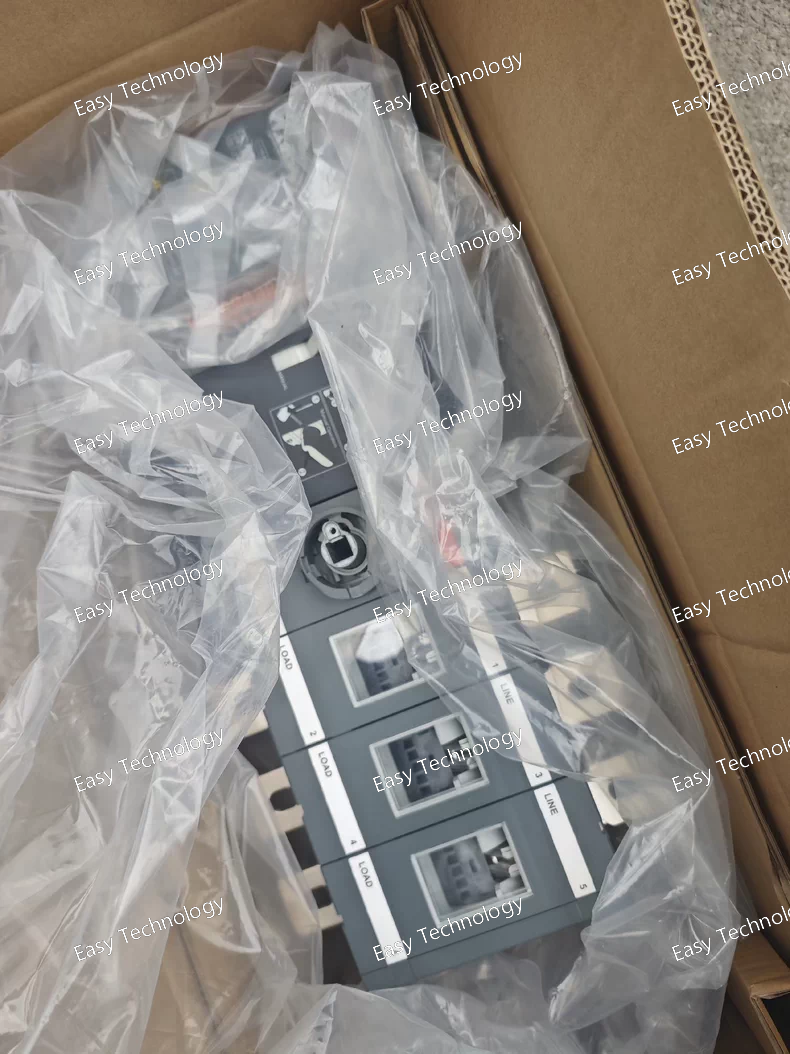
Technical Parameters Specification Typical Value / Description Product Type Motorized Automatic Transfer Switch / Change‑Over Switch Model OTM800E3C21D380C Number of Poles 4 poles (3 phases + neutral) Rated Operational Current 800 A (class rating) Rated Operational Voltage Up to 1000 V AC main circuit Rated Insulation Voltage (Ui) 1000 V AC Impulse Withstand Voltage (Uimp) ~12 kV Rated Short‑Time Withstand Current (1 s) ~20 kA Rated Operational Power (three‑phase) Approx. 450 kW @ 380–415 V Control / Motor Supply Voltage 380 V AC Transition Type Open transition change‑over Operating Modes Automatic motorized operation and manual handle override Mechanical Interlock Yes — prevents simultaneous connection of sources Mounting Panel or enclosure mount Typical Applications Automatic transfer between mains and backup generator in industrial/commercial three‑phase systems
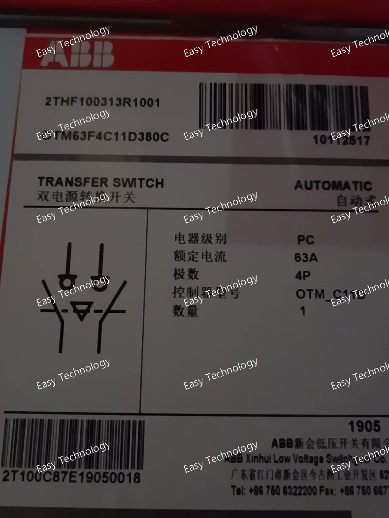
Technical Parameters Specification Typical Value / Description Product Type Motorized Automatic Transfer Switch / Change‑Over Switch Model OTM63F4C11D380C Number of Poles 4 poles (three phases plus neutral) Rated Operational Current 63 A Rated Operational Voltage Low‑voltage three‑phase AC distribution (nominal system up to ~380–415 V) Control / Motor Supply Voltage 380 V AC (indicated by the 380C suffix) Rated Insulation Voltage (Ui) Designed to operate within standard low‑voltage insulation levels (typical up to ~750–1000 V) Impulse Withstand Voltage (Uimp) Capable of withstanding several kilovolts of transient surge Transition Type Open‑transition change‑over (standard for this style) Operating Modes Automatic (motorized) and manual handle operation Mechanical Interlock Prevents simultaneous connection of both power sources Mounting Panel or enclosure mount for low‑voltage switchgear Typical Applications Automatic transfer between utility and backup sources; industrial and commercial power continuity
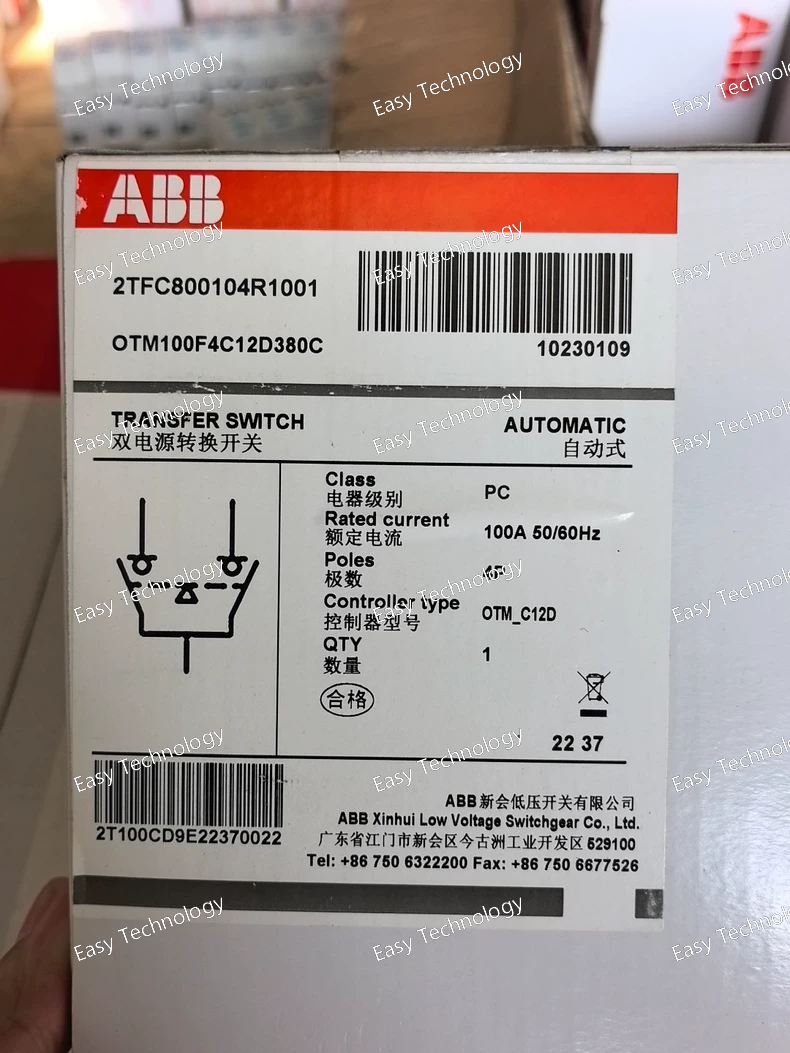
Specifications Parameter Category Specification Manufacturer / Series ABB / Softstarter TFC Series Model Code 2TFC800-104R1001 Rated Current 104 Amperes (This is the maximum rated operational current for the soft starter under specific conditions). Rated Voltage Typically 200-480V AC, 3-phase, 50/60 Hz (Confirm exact voltage range from local datasheet, as it can vary by market). Application For controlling Three-Phase AC Squirrel Cage Induction Motors. Power Rating Approximately 55 kW / 75 HP (at 400V AC). This is an approximate value; the exact power depends on the motor voltage and application. Control Method Voltage ramp control. It provides a smooth increase in voltage during start and a controlled decrease during stop (e.g., for pump control to avoid water hammer). Key Features • Reduced Starting Current: Limits inrush current, typically to 250-400% of motor full load current (FLC). • Torque Control: Provides high starting torque while minimizing mechanical shock. • Built-in Protection: Includes overload protection, phase imbalance detection, and thermal protection for the starter itself. • Compact Design: Integrated bypass contactor (or internal bypass) to reduce heat dissipation during continuous run. • User Interface: Typically includes a set of potentiometers or DIP switches for adjusting start/stop parameters and LEDs for status indication. Enclosure / Mounting Generally supplied as an open-type chassis for panel mounting (IP00). Requires installation in a suitable control cabinet for protection. Communication & Options Basic models often have analog/digital I/O for integration into control systems. Optional communication modules (e.g., Fieldbus) may be available. Standards & Compliance Conforms to international standards such as IEC/EN 60947-4-2, UL 508, and CE marked. Typical Applications Centrifugal Pumps Fans and Blowers Compressors Conveyor Belts Mixers and Agitators
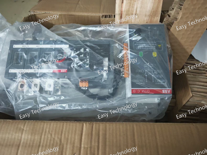
Technical Parameters Specification Typical Value / Description Product Type Automatic Transfer Switch (ATS) / Motorized Change‑Over Switch Model OTM100F4C10D380C Number of Poles 4 poles (three phases + neutral) Rated Operational Current 100 A Rated Operational Voltage Low‑voltage AC three‑phase (typically up to ~690 V) Control / Motor Supply Voltage 380 V AC Rated Insulation Voltage (Ui) Up to ~800–1000 V AC Impulse Withstand Voltage (Uimp) Several kilovolts Transition Type Open transition change‑over Operating Modes Automatic (motorized) and Manual (handle) Mechanical Interlock Prevents simultaneous connection of both sources Mounting Panel or enclosure mount Typical Applications Automatic transfer between utility and backup power in industrial/commercial systems
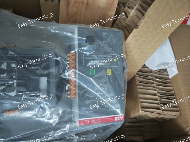
Parameter Specification Standards Compliance IEC/EN 60947-1 & 60947-2, UL 489, CCC, CE. Rated Operational Current (Ie) 100 A (Set via installed rating plug). Frame Current (Inm) 315 A Poles 4 Poles (3P + N) Rated Insulation Voltage (Ui) 1000 V Rated Operational Voltage (Ue) Up to 690 V AC Ultimate Breaking Capacity (Icu) 50 kA @ 415V AC (Category E) Trip Unit Type Electronic (PR221DS/PR222DS type) Key Protection Functions • L - Overload Protection: Adjustable current setting (Ir: 0.4 to 1 x In) and time delay (tr). • S - Selective Short-Circuit Protection: Adjustable current threshold (Isd: 1.5 to 10 x Ir) and adjustable time delay (tsd) for coordination. • I - Instantaneous Protection: Adjustable magnetic threshold (Ii: 2 to 14 x In). Auxiliary Functions • Communication Ready: Built-in port for optional communication modules (e.g., ABB COM-xx modules for Modbus, Profibus DP). • Measurement: Capable of monitoring current, power, energy, etc., visible via communication. Mounting Fixed Mounting Version (can be used with fixed or plug-in base/adaptor). Typical Applications Main and sub-distribution switchboards Industrial plant power distribution Protection of feeders, motors, and capacitor banks Integration into Building Management Systems (BMS) and SCADA via communication.
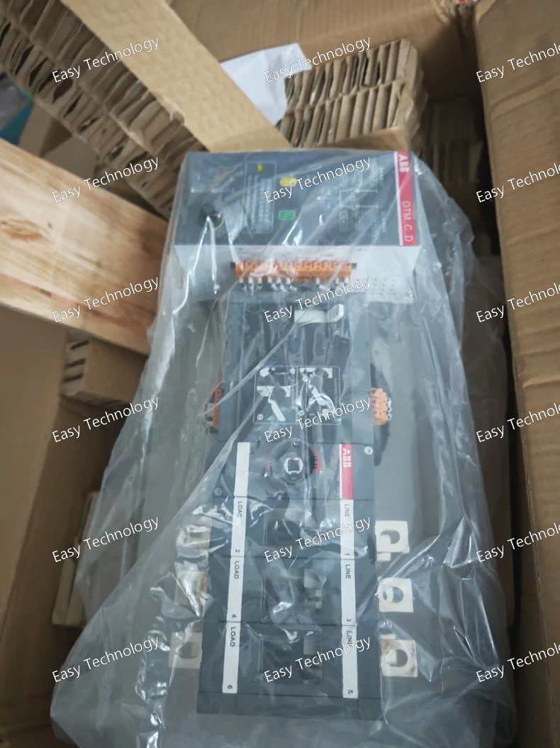
Technical Parameters Specification Typical Value / Description Product Type Motorized Automatic Transfer Switch (ATS) / Change‑Over Switch Model OTM160E3C10D380C Number of Poles 3 poles (three‑phase) Rated Operational Current 160 A Rated Operational Voltage Low‑voltage AC three‑phase (typically up to ~690 V AC) Rated Insulation Voltage (Ui) ~1000 V AC Rated Impulse Withstand Voltage (Uimp) ~12 kV (built to withstand typical surge conditions) Control / Motor Supply Voltage 380 V AC Transition Type Open transition change‑over (break‑before‑make) Operating Modes Automatic (motorized) and Manual (handle override) Mechanical Interlock Prevents both power sources from being connected simultaneously Mounting Panel or enclosure mount Typical Use Automatic transfer between utility and backup generator in three‑phase systems
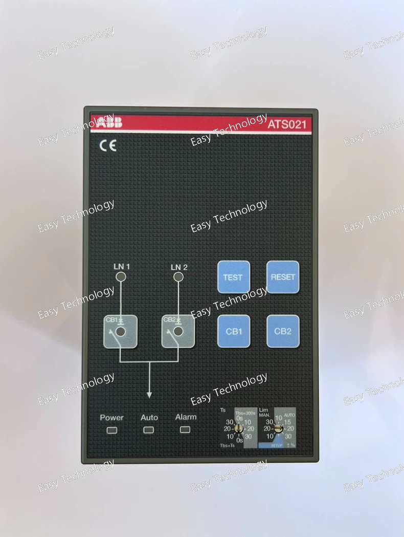
Technical Parameters Specification Typical Value / Description Product Name Automatic Transfer Switch Controller Model ATS021 Product Type Automatic Transfer Switch (ATS) / Transfer controller Function Monitors two power sources and controls switching between them Voltage Monitoring Monitors normal and emergency line voltages Switching Logic Automatic change‑over with configurable delays; manual control available Control Outputs Commands for opening/closing circuit breakers on both sources Operating Modes Automatic and Manual (selectable via front panel) User Interface Rotary switches, keypad/buttons with LED indicators Adjustable Parameters Delay times, voltage thresholds, test mode, manual override Mounting Panel or enclosure mount Dimensions (Approx.) Width ~160 mm × Height ~110 mm × Depth ~240 mm (compact) Weight ~1.2–1.3 kg Application Automatic transfer between mains and backup/generator power systems Protection & Monitoring Detects anomalies such as over/under voltage, missing line, imbalance
 TEL: Grace +86 13600179521
  Mail: info@hongkongeasy.com jilineasyyi@outlook.com
 Q Q:615739355
 ADDRESS:Unit 12, 20th Floor, Good View Commercial Centre, 2-16 Garden Street, Mong Kok, Hong Kong
 whats app


