
Industrial Controller
All product are in stock,guaranteed delivery within 3-7 days.


PRODUCT
PICTURE
BRAND
DESCRIBE
STOCK
DOWNLOAD
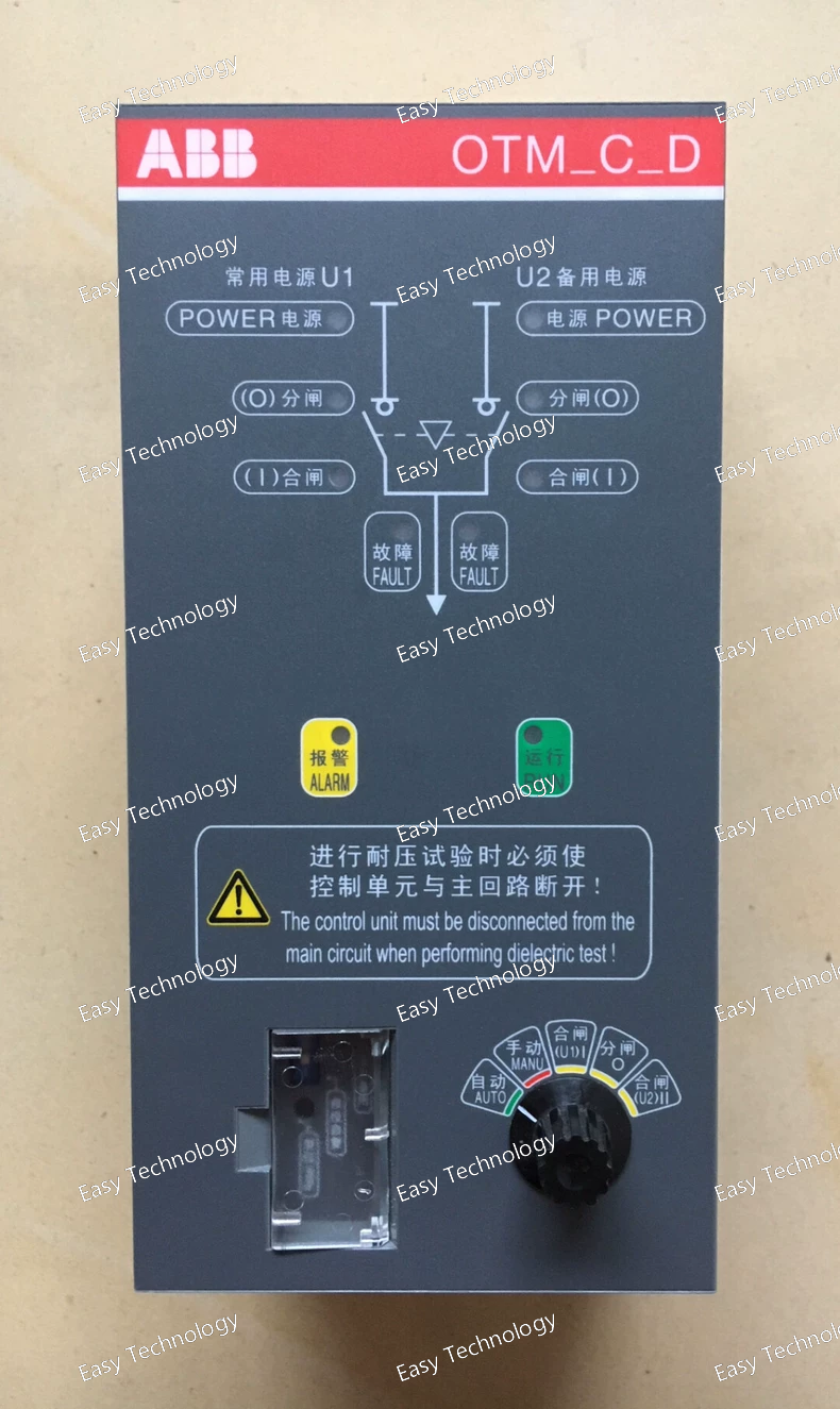
Technical Parameters Specification Typical Value / Description Product Type Compact Automatic Transfer Switch (ATS) / Motorized Change‑Over Switch Model / Variant OTM_C10D (fixed delay automatic change‑over variant) Function Automatic switching between two independent power sources Application Three‑phase low‑voltage systems (network/network or network/generator) Operating Modes Automatic motorized operation and Manual override Transition Type Open transition (standard change‑over) Voltage Monitoring Built‑in sensing for line availability Manual Operation Handle provided for local manual change‑over Control Interface Terminal connections for control and auxiliary signals Typical System Voltage Range Suitable for standard low‑voltage three‑phase (e.g., 380–415 V) Motor Supply Voltage Typically matched to system (e.g., 380 V AC) Compact Form Factor Designed for panel or enclosure mounting Auxiliary Outputs Switch position and alarm signals available Operation Delays Fixed (non‑adjustable) for transfer and return in the C10D variant Manual Override Option Provided via removable handle Safety Isolation Interlocking prevents both sources from paralleling Typical Uses Backup power switching in industrial, commercial, and infrastructure systems
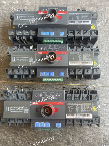
Technical Parameters Specification Typical Value / Description Product Type Automatic Transfer Switch (ATS) / Motorized Change‑Over Switch Model OTM100F4C21D380C Series OTM_C21D (compact ATS with configurable logic) Number of Poles 4 poles (three phases + neutral) Rated Current 100 A Rated Operational Voltage (Ue) 380–415 V AC (three‑phase) Control / Motor Supply Voltage 380 V AC Rated Insulation Voltage (Ui) Typical low‑voltage system range (e.g., ~800–1000 V AC) Impulse Withstand Voltage (Uimp) Several kilovolts designed for low‑voltage switching environments Transition Type Open transition (break‑before‑make transfer) Operating Modes Automatic (motorized) and Manual (handle override) Mechanical Interlock Prevents simultaneous connection of both power sources Mounting Panel or enclosure installation Typical Applications Automatic switching between utility and backup power sources in industrial and commercial power systems
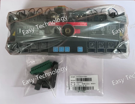
Technical Parameters Specification Typical Value / Description Product Type Motorized Automatic Transfer Switch (ATS) / Change‑Over Switch Model OTM125F4C21D380C Number of Poles 4 poles (three phases + neutral) Rated Operational Current 125 A Rated Operational Voltage 380 V AC three‑phase system Control / Motor Supply Voltage 380 V AC Controller Type C21D logic (automatic transfer logic integrated) Transition Type Open transition (break‑before‑make) Mechanical Interlock Yes — prevents simultaneous connection of both sources Mounting Panel or enclosure installation Typical Applications Utility ↔ backup generator load transfer in industrial and commercial systems Weight (approx.) ~3 kg (typical for compact 125 A units) Size Compact low‑voltage transfer switch format
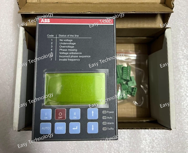
Technical Parameters (English) Specification Typical Value / Description Product Type Automatic Transfer Switch (ATS) Controller Model / Series OMD800E480C Intended Use Control logic for automatic switching between two power sources Compatible With Motorized change‑over switches (e.g., ABB OTM series) Voltage Monitoring Two sources monitored (LN1 & LN2) Phases Supported Single‑phase or three‑phase sensing per monitoring channel Control Outputs Commands to change‑over switch motor and breaker coils Operating Modes Automatic, Manual, Test User Interface LCD display with keypad and LEDs Communication Supports Modbus RTU for configuration and monitoring Adjustable Timing Transfer and return delays, dead bands, test timing Generator Control Start/Stop output for generator interface Auxiliary I/O Digital inputs and outputs for alarms and interlocks Mounting Panel or DIN‑rail mounting Dimensions Approx. 170 mm length (controller chassis) Typical Applications Automatic source transfer for mains ↔ generator in industrial/commercial systems
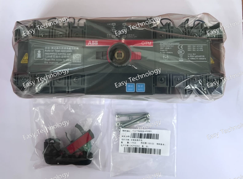
Technical Parameters Specification Typical Value / Description Product Type Motorized Automatic Transfer Switch (ATS) / Change‑Over Switch Model OTM100F4C20D380C Number of Poles 4 poles (three phases + neutral) Rated Operational Current 100 A Rated Operational Voltage Low‑voltage three‑phase AC distribution (commonly 380–415 V AC) Control / Motor Supply Voltage 380 V AC Rated Insulation Voltage (Ui) Suitable for low‑voltage systems (typically ~800–1000 V AC class) Impulse Withstand Voltage (Uimp) Kilovolt range for typical surge resilience Transition Type Open transition (break‑before‑make) Operating Modes Automatic (motorized) and manual handle operation Mechanical Interlock Yes — prevents simultaneous source connection Mounting Panel or enclosure mount Typical Application Automatic load transfer between utility and backup power in industrial and commercial systems
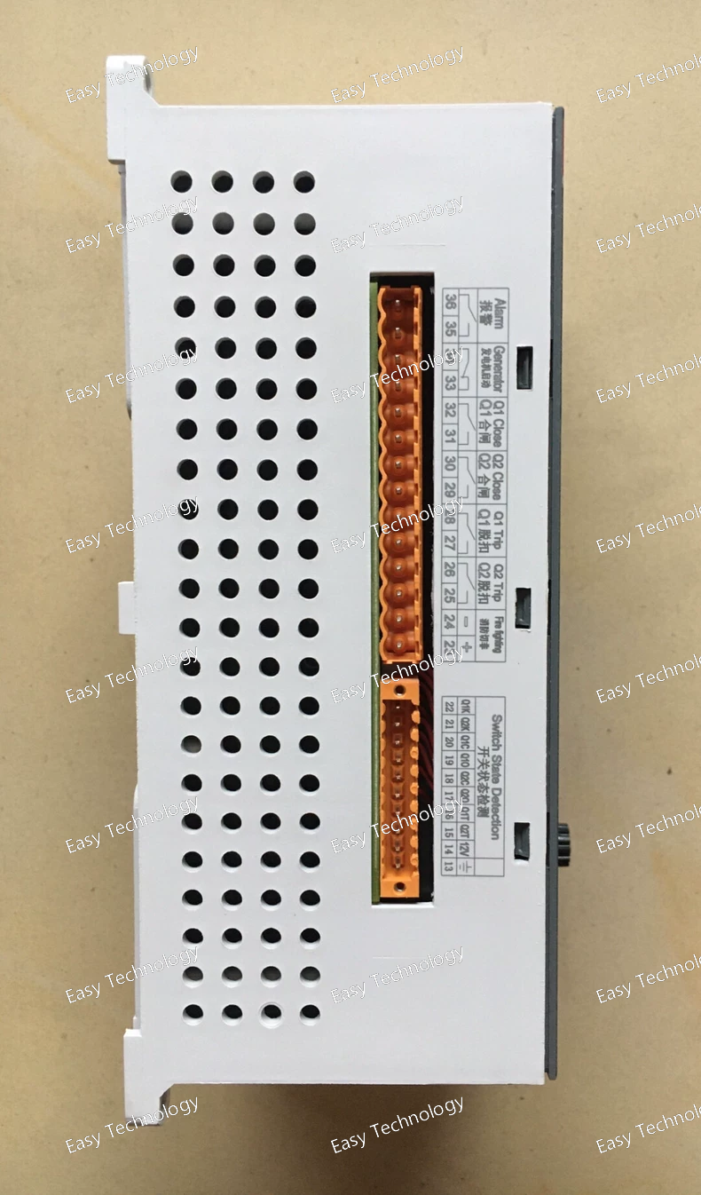
Technical Parameters (English) Specification Typical Value / Description Product Type Dual‑Power Automatic Transfer Switch / Controller Module Model DPT‑CB010 Function Automatic load transfer between two power sources with automatic back‑transfer Operating Mode Auto change‑over with self‑recovery (standard automatic return to primary source) Rated Current Range Designed to be used with switch bodies from 0.5 A up to ~250 A depending on variant Compatible Pole Configurations 2‑pole, 3‑pole, and 4‑pole versions available depending on switch used Short‑Circuit Breaking Capacity Several kA (e.g., up to ~36 kA or ~50 kA depending on installed switch) Voltage Monitoring Senses primary and secondary source voltages to determine transfer conditions Control Functions Automatic transfer, automatic return, alarms and status indication Manual Operation Provides manual change‑over capability in addition to automatic function Installation Mounted together with the matching DPT series transfer switch body Typical Application Industrial and commercial automatic power source change‑over systems Safety Features Mechanical and electrical interlocking (via the switch body) to prevent both sources connecting simultaneously
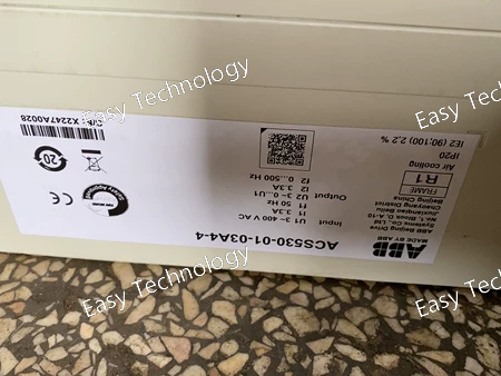
Technical Parameters Parameter Specification Model ACS530‑01‑03A4‑4 Drive Series ACS530 General Purpose Drives Drive Type Low‑Voltage AC Variable Frequency Drive (VFD) Rated Output Power 1.1 kW (approx. 1.5 HP) Rated Current (IEC) 3.3 A Input Voltage 3‑phase 380–480 V AC Input Frequency 50/60 Hz Output Frequency Range 0 – ~500 Hz Control Methods Standard V/f and sensorless vector control Enclosure / Protection IP20 / Open‑type Frame Size R1 Mounting Panel or cabinet installation Safety and Protection Overload, overcurrent, overvoltage, undervoltage protections User Interface Integrated control panel (LCD/keypad) Typical Applications Pumps, fans, conveyors, general machinery
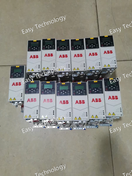
Technical Parameters Parameter Specification Model ACS380‑040S‑02A6‑4 Drive Series ACS380 Machinery Drive Drive Type Low‑Voltage AC Variable Frequency Drive (VFD) Input Voltage Three‑phase 380–480 V AC Rated Current ~2.6 A Rated Output Power 0.75 kW (≈1 HP) Control Methods Scalar (V/f), Sensorless vector control Output Frequency Range 0–599 Hz Enclosure Rating IP20 / Open Frame Size R1 Mounting DIN‑rail or wall mounting Integrated Display Icon‑based LCD control panel Dynamic Braking Supported with external resistor option Protection Functions Overcurrent, overvoltage, undervoltage, motor stall, etc. Application Examples Pumps, fans, conveyors, mixers, general machinery
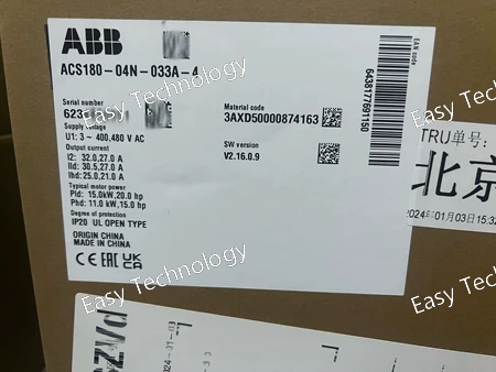
Technical Parameters Parameter Specification Model ACS180‑04N‑033A‑4 Drive Series ACS180 LV AC Machinery Drives Drive Type Low‑Voltage AC Variable Frequency Drive (VFD) Rated Output Power 15 kW (≈20 HP) IEC class Rated Current (IEC) ~32 A at 400 V AC Rated Current (UL) ~27 A at 460 V AC Input Voltage 3‑phase 380–480 V AC Input Frequency 47–63 Hz Control Methods Scalar (V/f); Sensorless vector control Enclosure / Protection IP20 (open/cabinet mount) Safety Function Integrated Safe Torque Off (STO) User Interface Configurable keypad/display (depends on option) Mounting Panel or cabinet installation Applications Pumps, fans, conveyors, mixers, general industrial motors
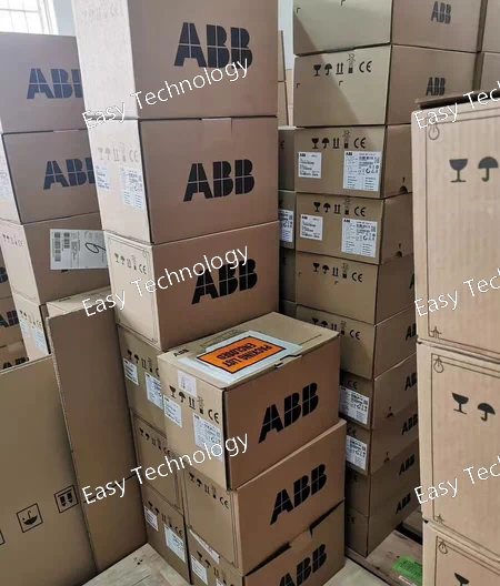
Technical Parameters Parameter Specification Model ACS380‑040S‑050A‑4 Drive Series ACS380 Machinery Drives Drive Type Low‑Voltage AC Variable Frequency Drive (VFD) Rated Output Power 22 kW (30 HP) Rated Current ~40–42 A Input Voltage 3‑phase 380–480 V AC Input Frequency 50/60 Hz Output Voltage 0–Input Voltage Control Methods Scalar (V/f), sensorless vector control Frequency Range 0–~500 Hz Enclosure / Protection IP20 / Open‑type Frame Size R4 Mounting Surface/Wall, Cabinet installation Overload Capability ~150 % for short duration Communication Modbus RTU (optional or built‑in) Safety Functions Standard drive protections (overvoltage, overcurrent, etc.) User Interface Integrated control panel (LCD or keypad) Operating Temperature Standard industrial range Typical Dimensions Approx. modular R4 size Weight ~4–5 kg Typical Applications Pumps, fans, conveyors, mixers, HVAC, packaging
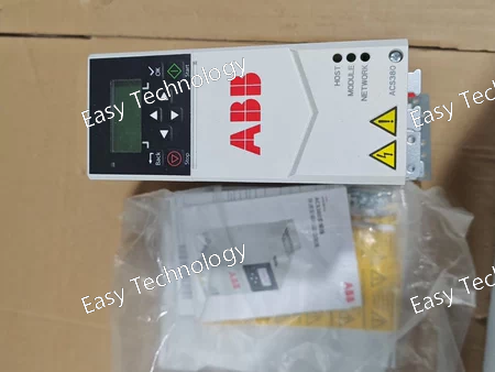
Technical Parameters Parameter Specification Model ACS380‑040S‑01A8‑4 Drive Series ACS380 Rated Power ~0.55 kW (~0.75 HP) Rated Current ~1.8 A Input Voltage 3‑phase 380–480 V AC Output Voltage 3‑phase 380–480 V AC Control Methods Scalar V/f; Vector control Frequency Range 0–599 Hz Overload Capability ~150% for short intervals Motor Types Supported Induction, PMSM, SynRM Safety Features Integrated Safe Torque Off (STO) User Interface Integrated icon‑based LCD panel Mounting DIN Rail / Wall mount Enclosure Rating IP20 / Open Frame Size R0 Dimensions (approx.) ~223 × 70 × 174 mm (varies by config) Operating Temp. Typical industrial range (‑10°C to +50°C) Adaptive Programming Yes (sequence macro)
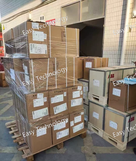
Technical Parameters Parameter Specification Model ACS530‑01‑07A3‑4 Drive Type Low‑Voltage AC Variable Frequency Drive (VFD) Rated Power ~3 kW Rated Current 7.2 A Supply Voltage 3‑phase 380–480 V AC Frequency Range 0–500 Hz Control Method Standard V/F or sensorless vector control (series capability) Overload Capacity Standard drive overload tolerance Protection Features Overload, short‑circuit, overvoltage, undervoltage, earth fault Communication Interfaces Built‑in Modbus RTU (RS‑485); optional fieldbus modules available User Interface Integrated control panel with display and navigation keys Application Industrial motor speed control for general machinery Mounting Wall or panel mount (standard)
 TEL: Grace +86 13600179521
  Mail: info@hongkongeasy.com jilineasyyi@outlook.com
 Q Q:615739355
 ADDRESS:Unit 12, 20th Floor, Good View Commercial Centre, 2-16 Garden Street, Mong Kok, Hong Kong
 whats app


