
Industrial Controller
All product are in stock,guaranteed delivery within 3-7 days.


PRODUCT
PICTURE
BRAND
DESCRIBE
STOCK
DOWNLOAD
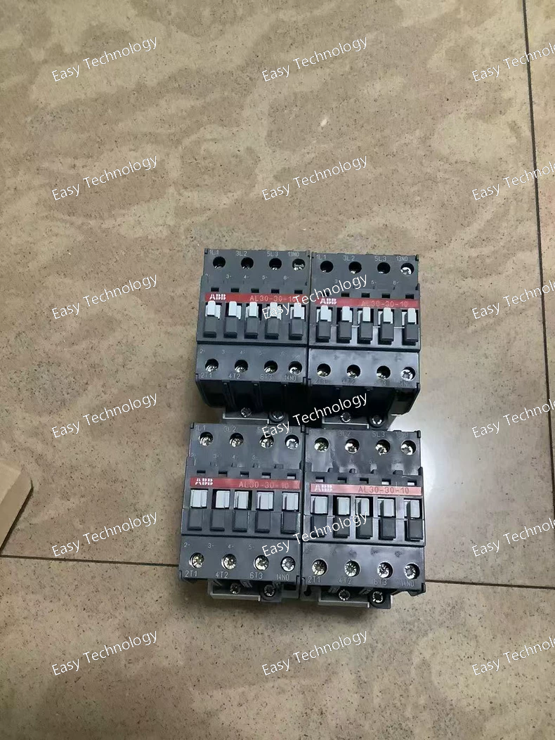
Technical Specifications Parameter Specification Part Number / Model 1SBL283001R8110 Product AL30‑30‑10 Power Contactor Contact Configuration 3 main poles + 1 auxiliary contact (1 NO) Rated Control / Coil Voltage 24 V DC Rated Operational Voltage (Main Circuit) up to 690 V AC Rated Operational Current AC‑3 (Ie) ~30–33 A (at 380–415 V AC) Rated Operational Current AC‑1 (Ie) ~55 A (at 690 V AC) Rated Operational Power AC‑3 (Pe) up to ~15 kW (at 380–415 V AC) Rated Breaking Capacity AC‑3 8 × Ie Auxiliary Contacts 1 Normally Open (1 NO) Max Switching Frequency up to ~1200 cycles/hour (AC‑3) Coil Consumption Low consumption DC coil (~3.5 W) Terminal Type Screw terminals Mounting DIN‑rail / Panel mount compatible Operating Frequency 50–60 Hz Rated Insulation Voltage (Ui) 1000 V (IEC) Rated Impulse Withstand Voltage (Uimp) 8 kV Ambient Temperature (Operating) –40 °C to +55 °C Degree of Protection IP20 Mechanical Life High mechanical durability typical for IEC 60947‑4‑1 block contactors Standards Compliance Designed to IEC 60947‑4‑1 and related industrial standards
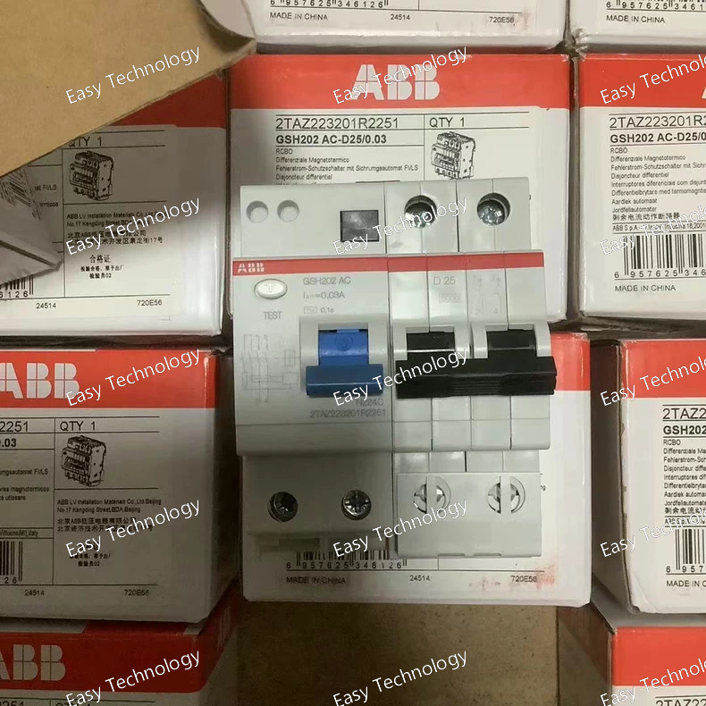
Technical Specifications Parameter Specification Part / Model GSH202 AC‑D25/0.03 Product Type Residual Current Operated Circuit Breaker (RCD / RCCB) Number of Poles 2 poles (2P) Rated Current (In) 25 A Rated Residual Current (IΔn) 30 mA Residual Current Type AC‑D (AC sensitivity with enhanced response) Rated Operational Voltage (Ue) 230 V AC (typical for low‑voltage systems) Rated Insulation Voltage (Ui) 500 V Rated Impulse Withstand Voltage (Uimp) 4 kV Operating Frequency 50/60 Hz Tripping Characteristic Instantaneous residual current trip Mounting DIN‑rail mounting Terminal Type Screw terminals Protection Functions Earth leakage / residual current protection Applications Protection against earth leakage and shock hazards in AC circuits Standards Compliance Designed to meet residual current device standards for type AC/D protection Typical Dimensions Standard modular width (~2 modules) and DIN‑rail footprint Typical Use Cases Final circuit earth fault protection in residential and commercial panels
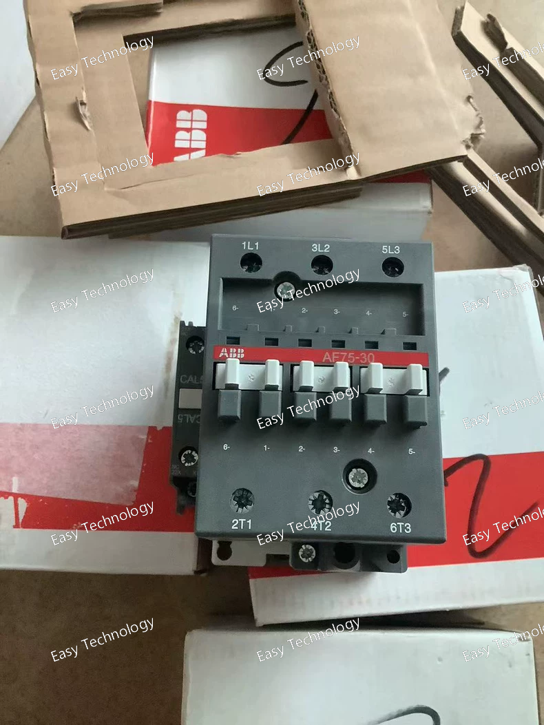
Technical Specifications Parameter Specification Part Number / Model 1SBL417001R7211 Series / Family AF Series (AF75‑30‑11) Product Type 3‑Pole Contactor (Control Unit) Coil Voltage 20 – 60 V DC Main Contact Configuration 3 poles (4 NO) Rated Contact Current 75 A (typical) Rated Operational Voltage (Main Circuit) up to 690 V AC Rated Power (AC‑3) ~37 kW at rated voltage Control Supply Type DC coil Operating Frequency DC control Auxiliary Contacts Integrated as per configuration (4 NO) Mounting DIN‑rail or panel mounting (screw terminals) Protection Class IP40 Ambient Temperature Range –40 °C to +70 °C Connection Type Screw terminals Function Motor and power circuit control
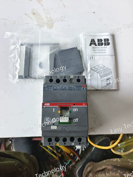
Technical Specifications Parameter Specification Part Number / Model 1SDA000174R1 Series / Family S1 / S1N Molded Case Circuit Breaker Product Type Automatic Circuit Breaker (Molded Case) Poles 3-pole (3P) Rated Current (In) 125 A Trip Unit Type Thermal-magnetic protection Rated Operational Voltage Typical low-voltage AC distribution (up to 480–690 V) Breaking / Interrupting Capacity High short-circuit breaking capability (specific ratings depend on variant) Terminal Connection Fixed terminals (front connection) Mounting Panel / switchgear installation Standards Compliance IEC/EN 60947-2 Application Protection of power distribution circuits, motors, feeders, and branch circuits Operation Manual toggle operator (lever)
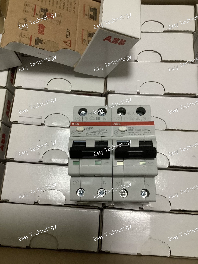
Technical Specifications Parameter Specification Part Number / Model 2CSR255180R1164 Series / Type DS201 C16 A30 RCBO Product Category Residual Current Circuit Breaker with Overcurrent Protection Poles 1P + N Rated Current (In) 16 A Rated Residual Current Sensitivity (IΔn) 30 mA Rated Operational Voltage (Ue) 230 V AC Rated Frequency 50–60 Hz Residual Current Type Type A Tripping Characteristic C curve Rated Short‑Circuit Breaking Capacity (Icu) 10 kA Rated Service Short‑Circuit Breaking Capacity (Ics) 7.5 kA Rated Insulation Voltage (Ui) 500 V Rated Impulse Withstand Voltage (Uimp) 4 kV Overvoltage Category III Pollution Degree 2 Number of Modular Widths 2 modules Contact Position Indication Red ON / Green OFF Fault Indication Blue flag on toggle Mounting DIN‑rail (35 mm) Terminal Type Screw terminals Electrical Endurance ~10,000 cycles Mechanical Endurance ~20,000 cycles Operating Temperature −25 °C to +55 °C Degree of Protection IP20 / IP40 Connection Capacity Solid: 0.75–25 mm², Stranded/Ferruled: 0.75–16 mm² Standards Compliance IEC/EN 61009‑1, IEC/EN 61009‑2‑1 Color / Housing Black toggle, grey body Weight (approx.) ~0.20 kg Dimensions (W×H×D) ~35 mm × 85 mm × 69 mm
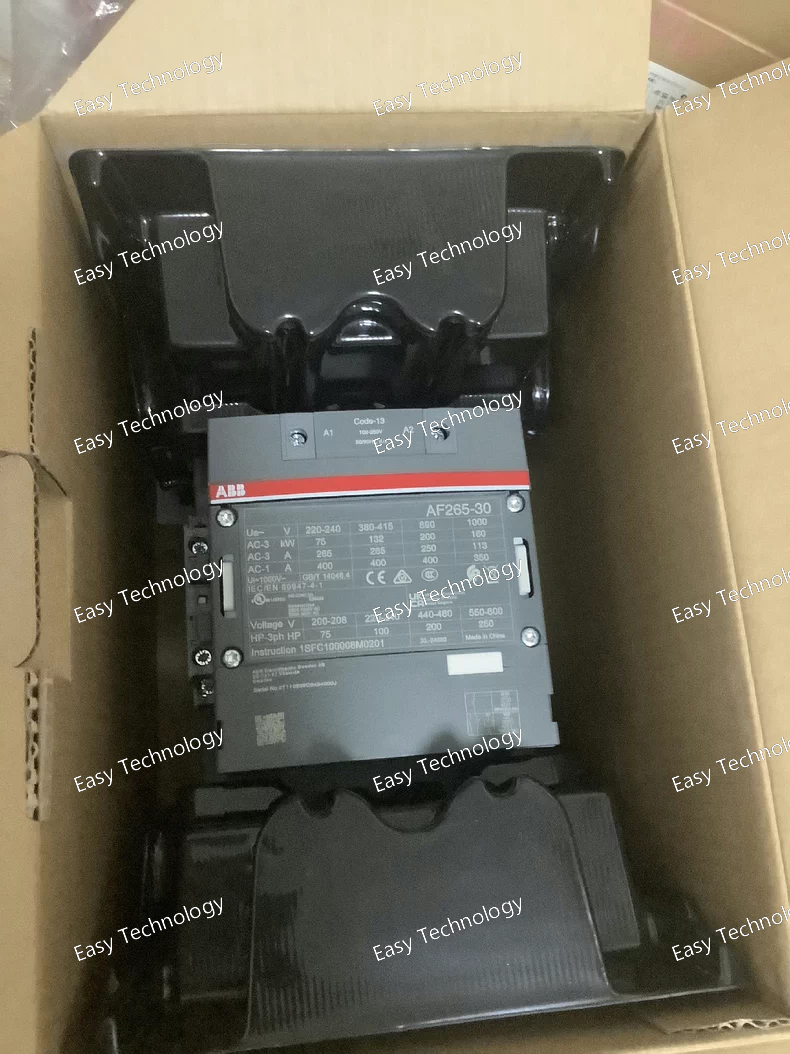
Technical Specifications Parameter Specification Part Number / Model AF265‑30‑11‑13 Product Type 3‑Phase Contactor Series AF Series Control / Coil Voltage 100–250 V AC/DC wide‑range coil Poles 3 Main Poles (3NO) Auxiliary Contacts 1 NO + 1 NC Rated Current 265 A (AC‑3) typical Rated Operational Voltage (Main Circuit) up to 1000 V (IEC) Impulse Withstand Voltage 8 kV (Main Circuit) Insulation Voltage 1000 V (IEC 60947‑4‑1) Mounting Type DIN rail / Panel mount Operating Temperature approx. −40 °C to +70 °C Mechanical Durability ~5,000,000 operations Auxiliary Contact Configuration 1NO + 1NC Standards Compliance IEC/EN 60947‑4‑1, UL, CSA Features Built‑in surge suppression, low coil power consumption, energy‑efficient electronic coil design Typical Applications Motor control, power switching, industrial automation, HVAC, pumps & compressors
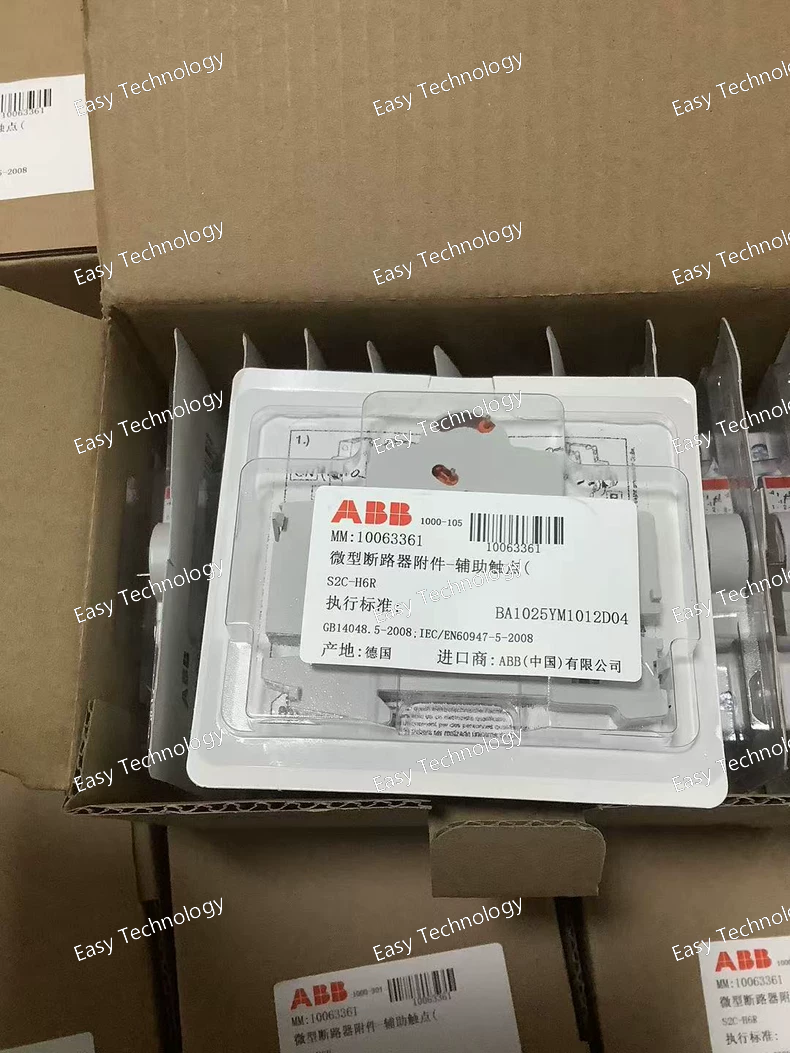
Parameter Specification Part Number 2CDS200912R0001 ABB Reference S2C‑H6R Function Auxiliary Contact / Signalling Switch Contact Configuration SPDT (1 Change-over Contact) Rated Current ~10 A (typical auxiliary duty) Rated Operational Voltage Compatible with AC/DC control circuits (e.g., 230 V AC common rating) Mounting Position Right-side mounting on compatible modular devices Suitable for Device Series MCB S 200 series, SN 201 series, RCCB F 200 series, RCBO DS201/DS202C and DS 200 series Standards Compliance IEC/EN 60947‑5‑1; UL 1077 Dimensions (approx.) Width 8.8 mm; Height 85 mm; Depth 69 mm Weight (approx.) 0.043 kg RoHS Status Compliant
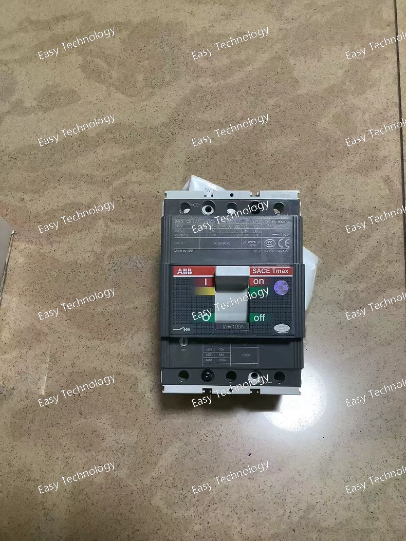
Technical Specifications Parameter Specification Part Number 1SDA051002R1 Product Type Moulded Case Circuit Breaker (MCCB) Series / Range Tmax T2S Pole Configuration 3‑pole (3P) Rated Current (In) 100 A Trip Unit Thermal‑magnetic (TMD), adjustable thermal setting 100‑1000 A Rated Insulation Voltage (Ui) 800 V Rated Operational Voltage (Ue) 690 V AC / 500 V DC Impulse Withstand Voltage (Uimp) 8 kV Rated Ultimate Short‑Circuit Breaking Capacity (Icu) up to 50 kA (varies by voltage) Rated Service Short‑Circuit Breaking Capacity (Ics) up to 85 kA (at lower AC voltages) Connection Type Fixed (front) terminals Version F Standards Compliance IEC 60947 Mechanical Durability ~25 000 operations Electrical Durability ~8 000 operations Weight ~1.1 kg Dimensions (W x H x D) ~90 mm x 130 mm x 70 mm
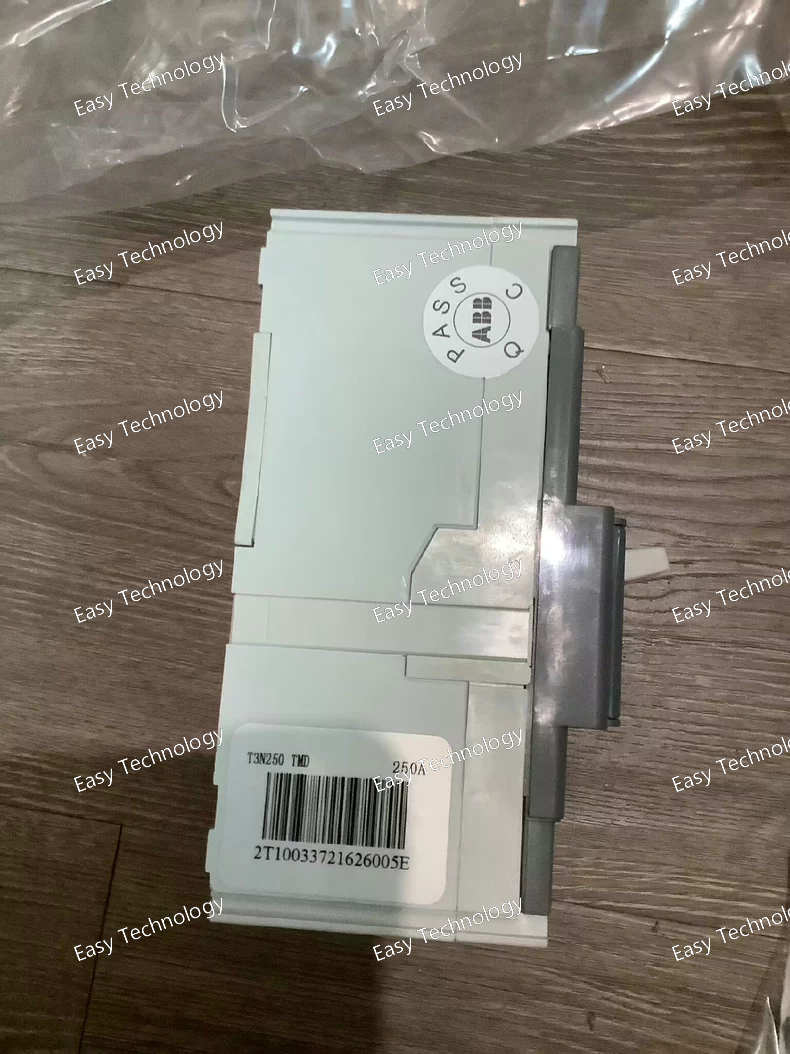
Technical Parameters Parameter Specification Product type Molded Case Circuit Breaker (MCCB) Product series ABB SACE Tmax XT3N Poles 3 poles Terminal type Fixed front terminals (FF) Trip unit type TMD (Thermal‑magnetic) Adjustable instantaneous (short‑circuit) setting 250 A to 2500 A Rated uninterrupted (frame) current 250 A Rated operational voltage (Ue) Up to 690 V AC / 500 V DC Rated insulation voltage (Ui) 800 V AC Rated impulse withstand voltage (Uimp) 8 kV Rated service short‑circuit breaking capacity (Ics) e.g., 37.5 kA @ 230 V AC, 27 kA @ 380–415 V AC (typical IEC values) Rated ultimate short‑circuit breaking capacity (Icu) Higher values depending on system voltage and configuration Protection functions Overload protection, short‑circuit protection Standards compliance IEC 60947‑2 (low‑voltage circuit breakers) Mechanical durability ~25,000 operations Electrical durability ~8,000 operations at rated load Mounting Fixed panel installation Typical applications Industrial and commercial power distribution, feeder protection, switchboards
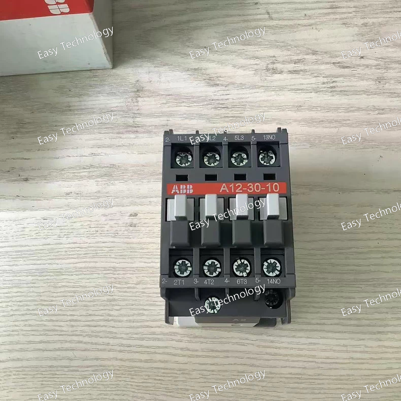
Technical Parameters Parameter Specification Product type Electromechanical magnetic contactor Product series ABB A series Poles (main contacts) 3 poles (3 NO) Coil/control voltage 110 V AC (50 Hz) / 110–120 V AC (60 Hz) Rated operational voltage (main) Up to 690 V AC Conventional free‑air thermal current (Ith) 28 A at 40 °C Rated operational current AC‑1 (Ie) ~27 A at 690 V Rated operational current AC‑3 (Ie) ~12 A at 415–500 V; ~9 A at 690 V Rated operational power AC‑3 ~3 kW at 230–240 V; ~5.5 kW at 380–415 V; ~7.5 kW at 500–690 V Rated operational current AC‑15 Up to 6 A at 24–127 V AC; 4 A at 220–240 V; 2 A at 500–690 V Making/breaking capacity 10 × Ie AC‑3 making; AC‑15 10 × Ie breaking Rated frequency limits 25–400 Hz Operating temperature –40 °C to +55 °C Coil power consumption ~74–80 VA pull‑in, ~8 VA holding Terminal type Screw terminals Auxiliary contacts Typically 1 NO auxiliary contact Mounting Panel / DIN rail (with adapter) Protection degree IP20 Standards IEC 60947‑4‑1 / IEC 60947‑5‑1 compliant Typical applications Motor starters, control panels, automation systems
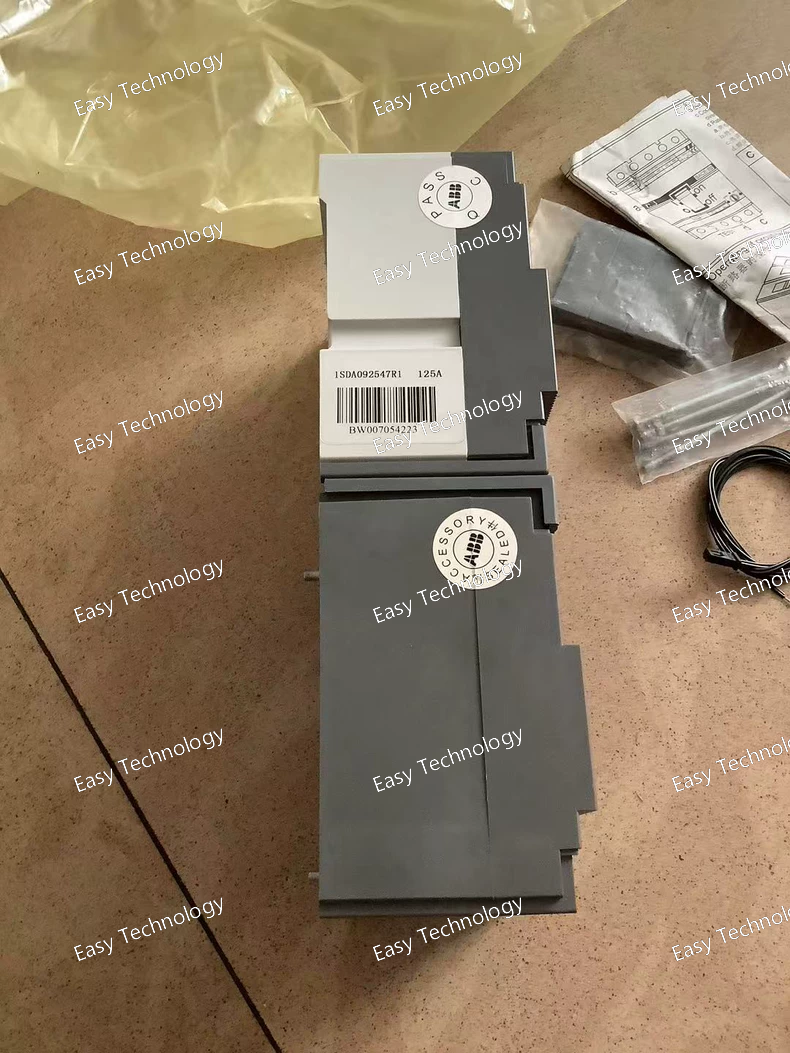
Technical Parameters (English) Parameter Specification Product type Molded Case Circuit Breaker (MCCB) Product family ABB S2N / SACE MCCB ABB Ordering Code 1SDA092547R1 Poles 4 poles (4P) Frame rating 160 A (S2N160 family typical) Trip unit type Thermal‑magnetic (adjustable) Current setting (overload) Typical adjustable range around R125 (e.g., 80 A–125 A) Rated operational current (In) 125 A setting (nominal value on listing) Rated operational voltage (Ue) Up to 690 V AC Rated insulation voltage (Ui) ~800 V AC Rated impulse withstand voltage (Uimp) 8 kV Breaking capacity Depends on exact C curve and variant (industrial MCCB level) Protection functions Overload & short‑circuit protection Terminal type Front fixed and front cable‑ready (FFC) Standards compliance IEC/EN 60947‑2 (typical for MCCBs) Mounting Fixed panel installation Typical applications Industrial / commercial power distribution and circuit protection
Technical Parameters Parameter / Requirement Typical Specification / ABB Compliance Standard Type IEC 60947‑4‑1 / EN 60947‑4‑1 Device Category Motor control and protection devices Scope Contactors, motor starters, thermal overload relays, manual starters Rated operational voltage (Ue) Up to 690 V AC / 500 V DC (depending on device) Rated insulation voltage (Ui) Up to 1000 V AC Rated current (Ie) Depends on device (e.g., MCCB, contactor, starter) Rated service short-circuit breaking capacity (Ics) Defined per device, e.g., MCCB 25–100 kA Protection functions Overload, short-circuit, phase-failure, motor stall Mechanical endurance Typically ≥25,000 operations for contactors, MCCBs Electrical endurance Typically ≥8,000–10,000 operations at rated load Operating temperature range -25 °C to +60 °C (typical) Mounting Panel, DIN rail, or chassis depending on device Environmental compliance IP20–IP65 (depending on enclosure and device type) Certification / Testing Type-tested according to IEC/EN 60947‑4‑1, CE marking, UL/CSA where applicable ABB Typical Products MS132/MS495 manual motor starters, T1/T2/Tmax MCCBs, XT/AX series contactors, AF/AX soft starters
 TEL: Grace +86 13600179521
  Mail:jilineasyyi@outlook.com
 Q Q:info@hongkongeasy.com
 ADDRESS:Unit 12, 20th Floor, Good View Commercial Centre, 2-16 Garden Street, Mong Kok, Hong Kong
 whats app


