
Industrial Controller
All product are in stock,guaranteed delivery within 3-7 days.


PRODUCT
PICTURE
BRAND
DESCRIBE
STOCK
DOWNLOAD
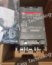
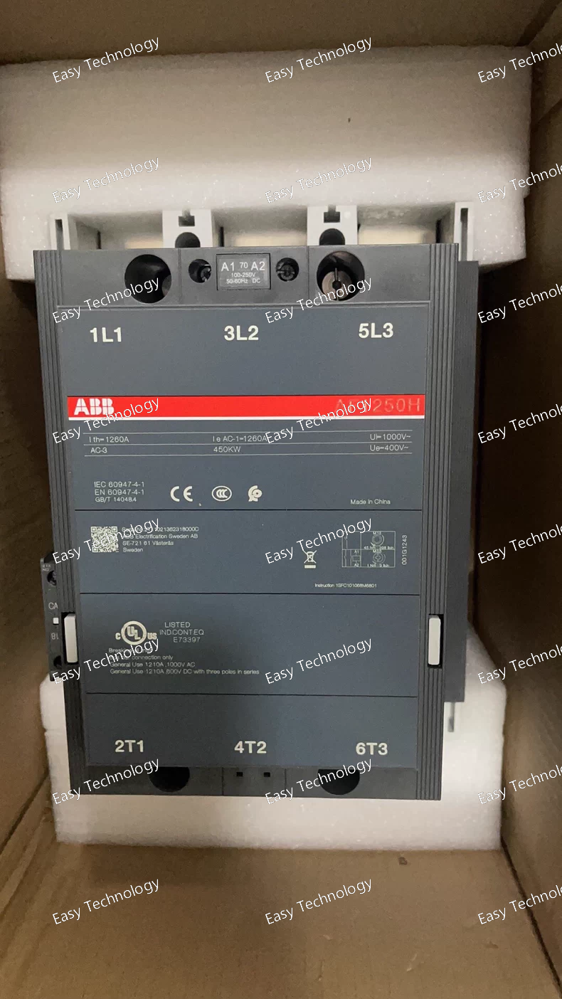
Technical Specifications Parameter / Item Value / Description Poles / Contacts 3 main poles — 3 × NO (normally open) Auxiliary Contacts 1 NO + 1 NC (standard “‑11” auxiliary contact set) Frame / Series AF750 (AF series large-frame contactor) Main Circuit Rated Operational Voltage (Ue) Up to 1000 V AC (IEC standard) / up to 600 V AC (UL/CSA rating) Control (Coil) Voltage Range (Uc) Wide‑range coil: e.g. 100–250 V AC/DC; other coil variants available (e.g. 24–60 V DC or 48–130 V AC/DC depending on order code) Utilization / Ratings (AC‑1, general / resistive load) ~ 1050 A (for many coil variants) — general-purpose load rating Utilization / Ratings (AC‑3, motor duty / inductive load) Ie (AC‑3) ~ 750 A @ typical 400 V (three‑phase) motor supply Rated Power (Motor Load, AC‑3) ~ 400 kW (at 400 V, three-phase) — typical motor power rating for this contactor Insulation & Withstand Ratings Rated insulation voltage (Ui): 1000 V (IEC) / 600 V (UL/CSA) Impulse withstand voltage (Uimp): 8 kV Making / Breaking Capacity Making capacity (AC‑3): up to 10 × Ie Breaking capacity (AC‑3): up to 8 × Ie Short‑Circuit / Short‑time Withstand Capability E.g. withstands short-time currents — under specified conditions allowed up to several kA for short durations (exact value depends on wiring/system) Terminal / Connection Type Main circuit: lug/bar‑type terminals (bus‑bar capable) Auxiliary / coil terminals: screw / lug terminals Mechanical & Environmental Operating ambient temperature range: –40 °C to +70 °C (without overload relay) Storage temperature: –40 °C to +70 °C Max installation altitude without derating: 3000 m Protection rating: Coil terminals IP20; main terminals (when open) IP00 Design / Features - Electronically controlled wide‑range coil, tolerant to supply/control‑voltage variation - Built-in surge suppression, stable operation under voltage dips/sags - Modular block‑type design, supports auxiliary contact blocks and accessories - Suitable for motor starting, heavy load switching, distribution, bypass, and general industrial power circuits
Technical Specifications Parameter Value / Description Configuration 3‑pole contactor, 3 main contacts (NO) Auxiliary Contacts 1 NO + 1 NC (standard auxiliary contact block) Main‑circuit Rated Operational Voltage (Ue) Up to 1000 V AC Conventional Free‑air Thermal Current (Ith) 600 A (open contactor, 40 °C) Rated Operational Current (AC‑1, Ie) 600 A @ 1000 V (40 °C), 500 A (55 °C), 400 A (70 °C) — and similarly 600/500/400 A @ 690 V depending on ambient temperature Rated Operational Current (AC‑3, Ie, motor duty) ~400 A @ 380/400/415/440/500 V (55 °C) ~350 A @ 690 V (55 °C) ~155 A @ 1000 V (55 °C) Rated Motor Power (AC‑3, Pe) ~110 kW @ 220–240 V AC 3‑phase ~200 kW @ 380–400 V ~220 kW @ 440–500 V ~250 kW @ 500 V AC ~315 kW @ 690 V AC Short‑time Withstand / Making / Breaking Capacity Making capacity up to 10 × Ie (AC‑3), breaking capacity up to 8 × Ie (AC‑3) Coil / Control Circuit Voltage (Uc) Wide‑range coil — typically 100–250 V AC (50/60 Hz) or 100–250 V DC (depending on coil version) Other Features - Supports large control‑voltage variation - Built‑in surge suppression (for coil circuit) - Modular design — add‑on auxiliary contact blocks and accessories supported - DIN‑rail or panel mounting compatible (depending on configuration) - Operating ambient temperature range: –40 °C to +70 °C (without thermal overload relay) / –25 °C to +50 °C (with overload relay) Typical Use Motor starting, control of three‑phase motors, industrial power switching, motor control centers, distribution circuits, general heavy‑duty load switching
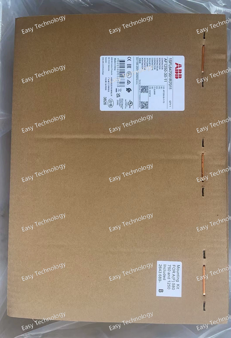
Technical Specifications Parameter Value / Description Poles / Contacts 3 main contacts (3 × NO) Auxiliary Contacts 1 NO + 1 NC (‑11 configuration) Main Circuit Rated Operational Voltage (Ue) Up to 1000 V AC Rated Operational Current (AC‑1 / general load) ~1250 A Control (Coil) Voltage (Uc) Wide-range coil: typically 100–250 V AC/DC Coil Features Electronic wide-range coil, tolerant to voltage variation, built-in surge suppression, stable switching under fluctuating control supply Applications Motor starting, isolation, bypass, power distribution, heavy-duty industrial circuits, three-phase motor control, general 3-phase load switching Auxiliary / Modular Design Modular block-type construction — allows add-on auxiliary contact blocks or accessories for expanded control/signaling circuits Durability / Reliability Designed for industrial-grade use, with robust main contacts and wide-range coil to manage supply variations; suitable for long-term heavy load switching
Technical Specifications Specification Value / Description Poles / Contacts 3‑pole, 3 main contacts (NO), auxiliary contacts: 1 NO + 1 NC Main Circuit Rated Operational Voltage (Ue) up to 1000 V AC Conventional Free‑air Thermal Current (Ith) 2650 A @ 40 °C (open contactor) Rated Operational Current AC‑1 (Ie, general/resistive load) 2650 A @ 40 °C (1000 V or 690 V); 2350 A @ 55 °C; 2120 A @ 70 °C Rated Making Capacity (AC‑3, motor or inductive load) up to 10 × Ie AC‑3 Short‑time Withstand / Breaking Capacity e.g. 10 s → 10,000 A (cold), 30 s → 7,500 A; 1 min → 5,500 A; 15 min → 2,200–2,800 A Rated Insulation Voltage (Ui) 1000 V (IEC 60947‑4‑1 / UL/CSA) Impulse Withstand Voltage (Uimp) 8 kV (main circuit) Coil / Control Circuit Voltage (Uc) 100–250 V AC (50/60 Hz) or 100–250 V DC (wide‑range coil) Coil Characteristics Electronic wide‑range coil, built-in surge suppression, tolerant to voltage dips/sags Mechanical and Physical 3‑pole block contactor, bar‑type main terminals, auxiliary screw terminals; net weight ~ 41–43 kg; dimensions approximately 438 mm (W) × 244 mm (D) × 422 mm (H) Utilization / Application High‑power motor control, power distribution, isolation, bypass, heavy industrial loads up to 1000 V AC
Parameters General Type: 3-pole industrial contactor Series: AF Large Frame Utilization Category: AC-3 / AC-1 Auxiliary Contacts: 1 NO + 1 NC (-11 configuration) Electrical Ratings Operational Voltage (Ue): up to 1000 V AC Rated Operational Current (Ie, AC-3): 2050 A (typical for this model) Rated Power (AC-3, 400/415 V): up to 1100–1200 kW Rated Impulse Withstand Voltage (Uimp): 8 kV Rated Insulation Voltage (Ui): 1000 V Control Coil Coil Type: AF electronic wide-range coil Control Voltage Range: Typically 100–250 V AC/DC or 250–500 V AC/DC (varies by coil code) Coil Characteristics: Wide voltage tolerance Low power consumption Built-in surge protection Mechanical Mechanical Durability: up to 20 million operations Electrical Durability: depends on load category; typically high for AF large-frame types Mounting: Fixed mounting (vertical recommended) Connections Main Terminals: Bar/bolted terminals for high-current conductors Auxiliary Terminals: Screw terminals Environmental Operating Temperature: −40 °C to +70 °C (varies slightly by version) Protection Class: IP00 (standard)
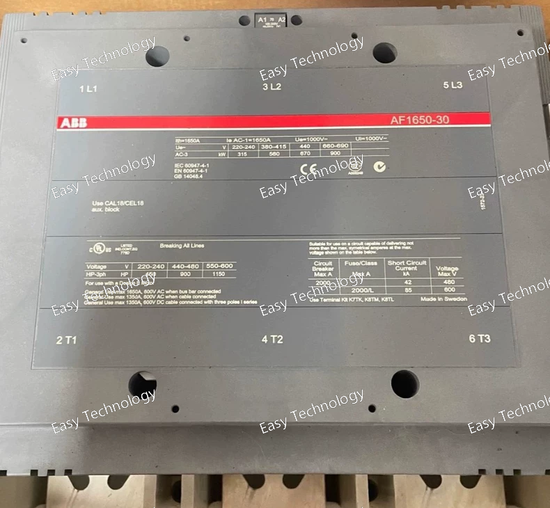
Technical Specifications General / Mechanical Contactor type: 3-pole power contactor, block (non-reversing IEC) Main contacts: 3 × normally-open (NO) contacts Auxiliary contacts: 1 NO + 1 NC auxiliary contact Rated main circuit voltage: up to 1000 V AC Frame / Series: AF1650 Termination: Screw or bar (bus-bar capable) main-circuit connection Dimensions (approx): Width 438 mm, Depth 244 mm, Height 392 mm Weight (net): ~ 33 kg Coil / Control Circuit Control (coil) voltage (Uc): 100–250 V AC (50/60 Hz) or 100–250 V DC Coil type: Electronic wide-range AF coil — tolerant of control-voltage variation, with built-in surge suppression Coil allows same unit to be used under different supply/control voltages without coil replacement Main Circuit Ratings & Performance Thermal / Continuous Load (AC-1 / General Loads): Conventional free-air thermal current (I_th): 1650 A (at 40 °C ambient) Rated operational current (I_e, AC-1): 1650 A @ 1000 V or 690 V at 40 °C 1450 A @ 1000 V or 690 V at 55 °C 1270 A @ 1000 V or 690 V at 70 °C Motor / Inductive Load (AC-3): Rated operational current (I_e, AC-3): ~1050 A at 220/230/240 V, 380/400 V, 415 V, 440 V (55 °C) ~950 A at 500 V (55 °C) ~950 A at 690 V (55 °C) Rated motor power (P_e, AC-3): ~315 kW at 220/230/240 V ~560 kW at 380/400 V ~630 kW at 415 V ~710 kW at 440–500 V ~1000 kW at 690 V ~600 kW at 1000 V Making capacity (AC-3): up to 10 × I_e (i.e. 10 × rated motor current) Short-Time & Short-Circuit Ratings Short-time withstand current (I_cw), cold state, 40 °C ambient free air: 10 s → 10,000 A 1 s → 12,000 A 30 s → 7,500 A 1 min → 5,500 A 15 min → 2,200 A Maximum breaking / making capacity: up to 12,000 A (depending on load power factor) Electrical / Environmental & Usage Conditions Suitable for switching AC resistive, inductive loads, motor circuits, general power circuits up to 1000 V Ambient temperature range (with thermal overload relay): –25 °C to +50 °C Ambient temperature range (without thermal overload relay): –40 °C to +70 °C Storage temperature: –40 °C to +70 °C Maximum permissible installation altitude: 3000 m Coil terminal protection: IP20; Main terminals (when open): IP00 Design & Features Wide-range AF electronic coil — no need to change coil for different control voltages (AC or DC) Built-in surge suppression — provides reliability under voltage dips or unstable supply Modular block-type design — easy integration in switchgear, with possibility to add auxiliary contact blocks and other accessories Robust main contacts and bus-bar capable connections — suitable for heavy-duty circuits, high-current and high-power switching
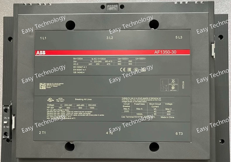
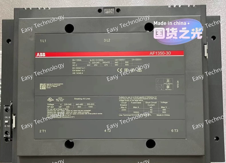
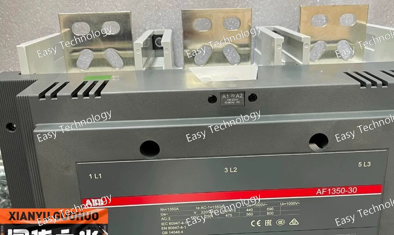
Technical Specifications General / Mechanical Contactor type: 3-pole power contactor, block (non-reversing IEC/UL) Main contacts: 3 × normally-open (NO) Auxiliary contacts: 1 NO + 1 NC auxiliary contact Frame size: AF1350 Main-circuit termination: bar / screw-terminal (bus-bar capable) Typical dimensions: approx. 438 mm (W) × 392 mm (H) × 244 mm (D) Typical weight: ~ 32 kg Coil / Control Circuit Rated control (coil) voltage (Uc): 100–250 V AC (50/60 Hz) or 100–250 V DC Coil type: Electronic wide-range AF coil, capable of handling significant control-voltage variation Built-in surge protection; tolerant of voltage dips/sags Coil consumption (at max control voltage): holding ~48 VA (AC 50/60 Hz), ~20.5 VA (DC) Main Circuit Ratings Rated operational (main circuit) voltage (Ue): up to 1000 V AC Rated insulation voltage (Ui): 1000 V (IEC) Conventional free-air thermal current (Ith): 1350 A (at 40 °C) Current & Power Ratings AC-1 (general / resistive loads) Ie (1000 V, 40 °C): 1350 A Ie (1000 V, 55 °C): 1150 A Ie (1000 V, 70 °C): 1000 A Ie (690 V, 40 °C): 1350 A Ie (690 V, 55 °C): 1150 A Ie (690 V, 70 °C): 1000 A AC-3 (motor duty / inductive loads) Ie (220 / 230 / 240 V, 55 °C): 860 A Ie (380 / 400 V, 55 °C): 860 A Ie (415 V, 55 °C): 860 A Ie (440 V, 55 °C): 860 A Ie (500 V, 55 °C): 800 A Ie (690 V, 55 °C): 800 A Typical rated motor power (AC-3): ~ 475 kW @ 400 V; up to ~ 800 kW at 690 V Operational Performance / Electrical Endurance Maximum electrical switching frequency (AC-1 / AC-2 / AC-4 / AC-3): 60 cycles/hour Making capacity (AC-3): up to 10 × Ie Short-time withstand current (Icw), cold state, 40 °C ambient: 10 s → 8,000 A; 30 s → 6,000 A; 1 min → ~4,500 A (varies by datasheet) Insulation withstand (impulse): main circuit 8 kV Terminal protection: coil terminals IP20; main terminals (open) IP00 Environment & Operating Conditions Ambient temperature (with thermal overload relay): –25°C … +50°C Ambient temperature (without thermal overload relay): –40°C … +70°C Storage temperature: –40°C … +70°C Permissible installation altitude: up to 3000 m above sea level Features / Design Highlights Wide-range control coil (100–250 V AC/DC) — no need for different coil versions for different control voltages Built-in surge protection — tolerant to supply voltage fluctuations, dips or sags Block-type modular design — allows add-on auxiliary contacts and accessories Heavy-duty main contacts and bus-bar capable terminations for high current, high-power circuits Compatible for motor starting, heavy load switching, power distribution, isolation, bypass etc.
Technical Specifications General / Mechanical Contactor type: 3-pole power contactor, non-reversing IEC block contactor Main contacts: 3 normally-open (NO) contacts Auxiliary contacts: 1 NO + 1 NC auxiliary contact Mounting / Terminals: Screw-terminal blocks, main circuit connected via bars / lugs Frame size: AF580 Control / Coil Circuit Control (coil) voltage (Uc): wide-range — typically for versions 100–250 V AC/DC. Some variants support 48–130 V AC/DC or higher coil voltages depending on the control coil fitted. Coil type: Electronic AF wide-range coil, with built-in surge protection and tolerance for voltage variation. Coil operating limits: 0.85 × Uc … 1.1 × Uc (at ambient up to 70 °C) Main Circuit Ratings Rated operational (main circuit) voltage (Ue): up to 1000 V AC Conventional free-air thermal current (Ith): 800 A (at 40 °C) Rated insulation voltage (Ui): 1000 V (IEC), 600 V (UL/CSA) Impulse withstand voltage (Uimp): 8 kV Operational Current & Power (AC-1 / AC-3) AC-1 (General / Resistive Loads) Ie (1000 V, 40 °C): 800 A Ie (1000 V, 55 °C): 700 A Ie (1000 V, 70 °C): 580 A Similar ratings for 690 V supply AC-3 (Motor Duty / Inductive Loads) Ie (415–500 V, 55 °C): ~580 A Ie (690 V, 55 °C): ~500 A Ie (1000 V, 55 °C): ~250 A Typical motor power ratings: ~315 kW @ 380/400 V ~355 kW @ 415–440 V ~400 kW @ 500 V ~500 kW @ 690 V ~355 kW @ 1000 V Breaking / Making / Withstand Capacity Breaking capacity (AC-3): up to 8 × Ie Making capacity (AC-3): up to 10 × Ie Short-time withstand current (Icw), cold start, 40 °C free air: e.g., 10 s → ~6400 A (varies by coil and variant) Maximum electrical switching frequency: up to 300 cycles/hour (for AC-1 and AC-3) Environment & Operating Conditions Ambient temperature (with thermal overload relay): –25 … +50 °C Ambient temperature (without thermal overload): –40 … +70 °C Storage temperature: –40 … +70 °C Maximum permitted installation altitude: 3000 m Design / Features Wide-range control coil allowing AC or DC control voltage without needing coil change Built-in surge protection — tolerant to supply voltage fluctuations and dips Screw-terminal, bar-type main connections suitable for large conductors or busbars Compact block-type design for panel or switchgear installation Auxiliary contact offers flexibility for control or signaling circuits
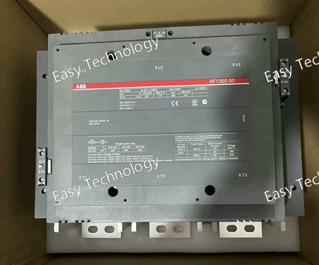
Technical Specifications General / Mechanical Contactor type: 3-pole power contactor (non-reversing IEC type) Main contacts: 3 normally-open (NO), 0 normally-closed (NC) Auxiliary contacts: 1 NO + 1 NC (standard) Mounting type: Fixed block-type contactor Application: Motor control, power distribution, isolation, bypass, heavy-load switching Coil / Control Circuit Rated control (coil) voltage: 100–250 V AC (50/60 Hz) or 100–250 V DC Coil type: Electronic wide-range coil (AC/DC) with built-in surge protection Coil operating range: 0.85 × Uc to 1.1 × Uc (at ambient ≤ 70 °C) Main Circuit Ratings Rated operational voltage (Ue): Up to 1000 V AC Conventional free-air thermal current (Ith): 2050 A (at 40 °C) Insulation voltage (Ui): 1000 V (IEC standard) Impulse withstand voltage (Uimp): 8 kV Current & Power Ratings Utilization Type Rating AC-1 (resistive/general load) 2050 A @ 1000 V, 40 °C 1750 A @ 1000 V, 55 °C 1500 A @ 1000 V, 70 °C 2050 A @ 690 V, 40 °C / 1750 A @ 55 °C / 1500 A @ 70 °C AC-3 (motor duty) 1060 A @ 220–415 V (typical 55 °C) 970 A @ 500–690 V (55 °C) 425 A @ 1000 V (55 °C) Rated motor power (AC-3) ~630 kW @ 415 V, ~710 kW @ 440 V, ~1000 kW @ 690 V, ~630 kW @ 1000 V Withstand & Making Capacity Short-time withstand current (Icw), cold start, at 40 °C: 10 s → 10 000 A 1 s → 12 000 A 30 s → 7 500 A 15 min → 2 200 A Making capacity for AC-3: up to 10 × Ie (i.e. up to ten times the rated motor current) under appropriate conditions Electrical / Mechanical Performance Coil consumption: holding coil ~48 VA (AC), pull-in ~2450 VA (AC) / ~2290 VA (DC) Electrical switching frequency (AC-1): max 60 cycles/hour Mechanical switching frequency: max 300 cycles/hour Mechanical durability: ~500,000 operations Terminal connection capacity (main circuit): up to bar 100 mm² Terminal connection capacity (auxiliary circuit): flexible 2 × 0.75–2.5 mm² or solid 2 × 1–4 mm² wire Environment & Ambient Conditions Operating ambient temperature (with thermal overload relay): −25 … +50 °C Without thermal overload relay: −40 … +70 °C Storage temperature: −40 … +70 °C Maximum permissible installation altitude: 3000 m Degree of protection: Coil terminals IP20, Main terminals (when open) IP00 Design / Features Wide-range electronic coil requiring no coil change for different control voltages (AC or DC) Built-in surge protection — tolerant of voltage dips and unstable supply Modular — supports auxiliary contact blocks and various accessories Robust block-type design suitable for industrial switchgear, generators, large motors
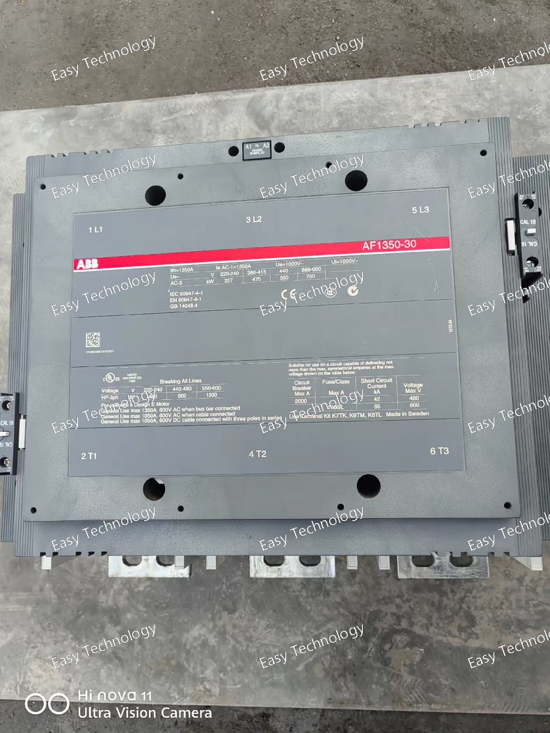
Technical Parameters General Contactor type: 3-pole power contactor Main contacts: 3 NO Auxiliary contacts: 1 NO + 1 NC Mounting method: Fixed, block-type Application: Motor starting, industrial load switching, AC power circuits Control / Coil Circuit Rated control (coil) voltage: 100–250 V AC (50/60 Hz) or 100–250 V DC Coil technology: Electronic AF wide-range coil Built-in surge suppression: Yes Main Circuit Ratings Rated operational voltage (Ue): Up to 1000 V AC Rated insulation voltage (Ui): 1000 V Conventional thermal current (Ith): 1650 A (at 40°C) Rated Operational Current & Power AC-1 (resistive load) Ie (40°C): 1650 A Ie (55°C): approx. 1450 A Ie (70°C): approx. 1270 A AC-3 (motor duty) Ie at 380/400 V: approx. 1060 A Ie at 690 V: approx. 970 A Rated motor power (Pe): ~315 kW at 230 V ~560 kW at 400 V ~630 kW at 415 V ~710 kW at 440/500 V ~1000 kW at 690 V ~600 kW at 1000 V Withstand Capacity Short-time withstand current (Icw): 10 s: approx. 10,000 A 1 s: approx. 12,000 A 30 s: approx. 7,500 A 1 min: approx. 5,500 A Mechanical / Environmental Mechanical endurance: approx. 250,000–500,000 operations Operating temperature: −25°C to +50°C (typical) Storage temperature: −40°C to +70°C Maximum installation altitude: 3000 m Degree of protection: IP00 (main terminals), IP20 (coil terminals) Design Features Wide-range electronic coil improves stability under voltage variation Reduced coil power consumption Pre-mounted auxiliary contacts included Compatible with auxiliary modules and accessories Heavy-duty frame suitable for industrial environments
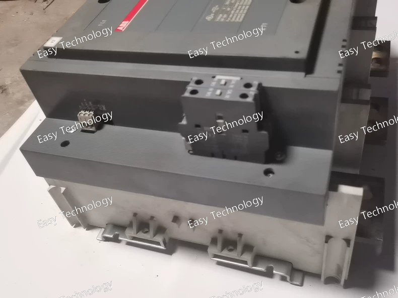
Technical Parameters General Product type: 3-pole power contactor Main contacts: 3 NO Auxiliary contacts: 1 NO + 1 NC Mounting type: Fixed, block-type Application: Motor control, power switching, industrial loads Coil / Control Circuit Rated control voltage (Uc): 100–250 V AC (50/60 Hz) / 100–250 V DC Coil technology: AF electronic wide-range coil Built-in surge suppression: Yes Main Circuit Ratings Rated operational voltage (Ue): Up to 1000 V AC Rated insulation voltage (Ui): 1000 V Impulse withstand voltage (Uimp): 8 kV Current Ratings AC-1 (resistive load): approx. 1350 A AC-3 (motor duty): approx. 800–860 A depending on voltage Rated motor power: ~475 kW @ 400 V up to ~800 kW @ 690 V Withstand Ratings Short-time withstand current (Icw): 8000 A for 10 seconds 6000 A for 30 seconds Mechanical / Environmental Mechanical endurance: approx. 500,000 operations Operating temperature: −25°C to +50°C (typical) Storage temperature: −40°C to +70°C Degree of protection: IP20 (terminals), body per standard industrial rating Design Features Electronic wide-range coil tolerant of fluctuations Low power consumption Modular accessory compatibility Pre-mounted main circuit bars and auxiliary contacts
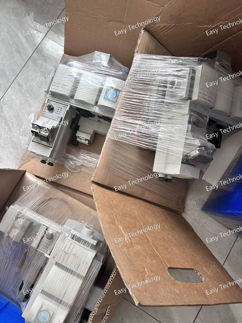
Key Specifications Application: Air-Insulated (AIS) or Metal-Clad Switchgear. Mounting: Fixed (permanently bolted in). Operation: Spring-operated mechanism, motor-charged. Protection: Digital protective relay (MPU or similar) with integrated current transformers. Key Safety Feature: Automatic Grounding Device for maintenance safety. Typical Voltage: 5 kV, 7.2 kV, 12 kV, or 15 kV class. Typical Current: ~2000A (based on C2M frame). Short-Circuit Breaking Capacity: ~50 kA.
 TEL: Grace +86 13600179521
  Mail: info@hongkongeasy.com jilineasyyi@outlook.com
 Q Q:615739355
 ADDRESS:Unit 12, 20th Floor, Good View Commercial Centre, 2-16 Garden Street, Mong Kok, Hong Kong
 whats app


