
Industrial Controller
All product are in stock,guaranteed delivery within 3-7 days.


PRODUCT
PICTURE
BRAND
DESCRIBE
STOCK
DOWNLOAD
Technical Parameters General Product Type: Manual motor protector (MMP) Model: MP2‑41R‑10 Operator Style: Rotary selector (ON/OFF/RESET) Number of Poles: 3‑pole (three‑phase) Trip Elements: Thermal overload + magnetic (instant trip) Electrical Ratings Rated Operational Voltage (Ue): Up to 690 V AC Rated Insulation Voltage (Ui): Appropriate for low‑voltage motor control circuits Motor Protection: Combined thermal and magnetic protection Adjustable Trip Current: Adjustable range around the 41 A frame (actual trip range typically spans lower and higher than 41 A depending on connector kit) Breaking Capacity: Suitable for motor load breaking at rated current Trip Class: Standard industrial thermal class for motors Motor Protection Features Thermal Overload Protection: Trips on sustained overload conditions Magnetic Instantaneous Protection: Trips quickly on high fault currents Phase‑Failure Protection: Detects and trips on loss of one phase Manual Reset: Rotary reset (R) after trip event Control & Operator Operator Positions: ON – OFF – RESET Manual Start/Stop: Yes Trip Indication: Visible actuator position change on trip Mechanical Mounting: Panel / DIN rail mountable with adapter (depending on kit) Terminal Connections: Screw terminals for line and load Construction: Rugged housing for industrial use Mechanical Life: High for repeated motor starting/stopping Environmental Operating Ambient Temperature: Typical industrial ambient range (e.g., −20 °C to +60 °C) Storage Temperature: Standard industrial storage range Pollution Degree: Suitable for industrial environments Applications Motor protection and control in industrial equipment Pump, fan, compressor, and conveyor motor circuits Motor control centers and control panels Protection against overload, short circuit, and phase loss Manual start/stop operations with integrated protection
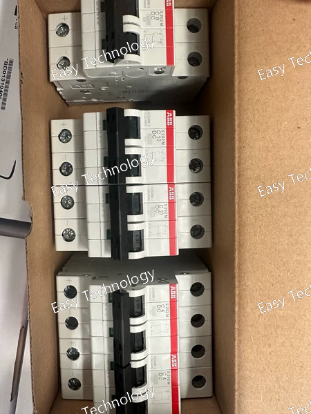
Technical Parameters General Product Type: Miniature Circuit Breaker (MCB) Model: S201‑C1 Series: System pro M compact S200 Number of Poles: 1 (single‑pole) Trip Curve / Characteristic: Type C (thermal‑magnetic) Mounting: DIN rail (IEC 60715 TH35) Terminal Type: Screw terminals Rated Operational Conditions: Residential, commercial, light industrial Electrical Ratings Rated Current (In): 1 A Rated Operational Voltage: 277/480 V AC (UL rating) 230/400 V AC (IEC rating) Rated Insulation Voltage (Ui): 440 V Rated Impulse Withstand Voltage (Uimp): 4 kV Rated Breaking Capacity: 6 kA (IEC/EN 60898‑1) at 230/400 V AC Rated Ultimate Short‑Circuit Breaking Capacity (Icu): Up to 10 kA at lower voltages Rated Service Short‑Circuit Breaking Capacity (Ics): Typical fraction of Icu (e.g., ~7.5 kA) Rated Frequency: 50/60 Hz Utilization Category: Suitable for overload and short‑circuit protection Mechanical & Physical Actuator: Toggle ON/OFF switch Mechanical Life: High (designed for many switching cycles) Terminal Protection: IP20 Panel Protection: Depends on panel enclosure Installation Height: Standard modular width 17.5 mm Approx. Dimensions: ~69 mm (depth) × 17.5 mm (width) × ~88 mm (height) Pollution Degree: 3 Environment Operating Temperature: ‑25 °C to +55 °C ambient Storage Temperature: Typical industrial storage range Compliance Standards: IEC/EN 60898‑1, IEC/EN 60947‑2, UL 1077, CSA C22.2 Features & Applications Thermal‑magnetic trip mechanism for combined overload and short‑circuit protection Compact DIN‑rail mountable design for distribution boards Finger‑safe terminals for enhanced safety in panel use Designed for protection of branch circuits, lighting, receptacles, and small loads Accepts optional accessories (auxiliary contact, shunt trip, alarm contact)
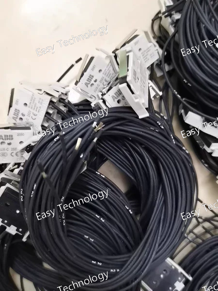
Technical Parameters General Product Type: Auxiliary contact module for molded case circuit breakers (MCCB) Model: AUX‑C 1Q1SY 250 V (T1‑T3) Contact Configuration: 1 Changeover contact (1Q): indicates breaker open/closed position 1 Changeover contact (1SY): indicates trip/fault event Number of Contacts (SPDT): 2 changeover contacts Electrical Ratings Rated Voltage (AC/DC): Up to 250 V AC/DC for signaling circuits Utilization Categories: Suitable for control and signaling use per applicable industrial categories (e.g., AC‑15/DC‑13) Typical rated currents at 250 V AC/DC consistent with auxiliary contact usage Standards Compliance: Designed to meet IEC 60947‑2 and related safety standards Contact Type: Silver alloy or equivalent industrial contact material for reliable switching Compatibility Suitable Breaker Families: ABB Tmax XT series breakers Dedicated slots for T1/T2/T3 accessory positions Mounting Position: Installed externally on the right‑hand side accessory slot of the breaker Pre‑cabled Version: Supplied with approx. 1 m of cable for easy connection Mechanical & Installation Connection: Pre‑wired cable termination for remote connection to control or indicator circuits Mounting: Plug‑in or snap‑on accessory for compatible breaker accessory slot Dimensions & Weight: Compact module that fits within breaker accessory space Operating Orientation: Mounts in the specified accessory slot(s) without modification Environmental Operating Temperature Range: Suitable for typical industrial panel ambient conditions Pollution Degree: Industrial pollutions (IEC categorization) Protection: Front should be protected when installed behind the panel face Functions & Uses Breaker position indication: Shows whether the breaker is closed (ON) or open (OFF) Trip indication: Signals when the breaker has tripped due to overload or fault Remote control feedback: Ideal for PLC, annunciators, control circuits, or automation monitoring AC/DC control systems: Works with both AC and DC control voltages up to 250 V Key Features Dual changeover contacts for combined position and trip status Pre‑wired cable for easy integration Broad voltage compatibility with AC/DC up to 250 V Direct mounting to ABB Tmax XT breaker accessory slot Enhanced monitoring for breaker control and safety logic
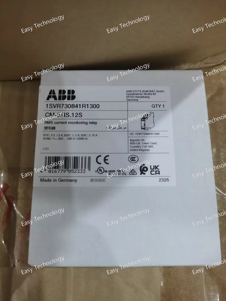
Technical Parameters General Product Type: Current monitoring relay (single‑phase) Model: CM‑SRS.12S Series: CM monitoring relay range Mounting: DIN‑rail mountable Connection Type: Screw connection with double‑chamber cage terminals Monitoring & Measurement Current Measurement Principle: RMS measurement of AC and DC current Measuring Ranges (selectable): 0.3 – 1.5 A 1 – 5 A 3 – 15 A Monitoring Type: Configurable for overcurrent or undercurrent detection Hysteresis: Adjustable (approx. 3 % – 30 % of threshold) Control / Output Output Contact: 1 × Changeover (SPDT) Contact Rating: Up to 250 V AC / 4 A (control/relay output) Contact Function: Relay output for control or signaling Electricals Rated Control Supply Voltage: Wide range versions: 24 – 240 V AC/DC for universal supply 220 – 240 V AC only (control voltage variant) Voltage Type: AC/DC compatible (on universal versions) Operating Phase: Single‑phase current monitoring Performance & Operation Response Types: Overcurrent and undercurrent trip based on set thresholds Adjustment: Threshold and hysteresis adjustable via front controls Status Indication: Relay output state visible via mechanical indicator Mechanical & Physical Dimensions: Width: ~22.5 mm Height: ~85.6 mm Depth: ~103.7 mm Weight: ~0.14 – 0.19 kg depending on variant Housing: Industrial DIN‑rail relay enclosure Environmental Operating Temperature: Suitable for typical industrial ambient temperature ranges Pollution Degree: Designed for industrial environments Protection: Front panel protection per standard enclosure specs Applications Overcurrent and undercurrent monitoring in industrial control panels Protection and alarm systems for motors and loads Automation systems requiring current supervision Control logic interfaces for contactors, breakers, and PLCs **Single‑phase power monitoring in machine and equipment enclosures
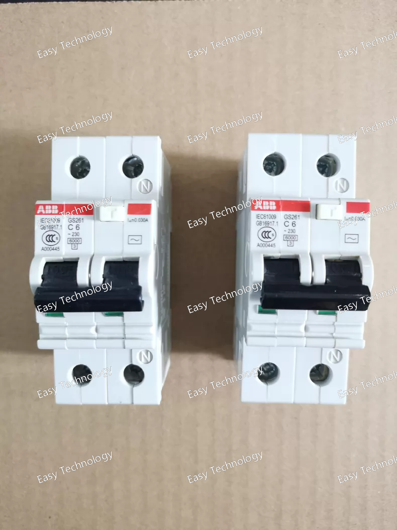
Technical Parameters General Product Type: Residual current circuit breaker with overcurrent protection (RCBO / leakage circuit breaker) Model: GS261‑C6/0.03 Number of Poles: 2 (phase + neutral) Trip Curve: Type C (thermal‑magnetic characteristic) Series: ABB GS261 family Current & Leakage Protection Rated Current (In): 6 A Residual (Leakage) Current Sensitivity (IΔn): 0.03 A (30 mA) for earth‑leakage trip Protection Functions: Overload protection Short‑circuit protection Residual current / earth‑leakage protection Electrical Ratings Rated Operational Voltage: ~230 V AC (single‑phase systems) Frequency: 50 / 60 Hz Rated Breaking Capacity: ~6 kA (typical for small RCBOs) Rated Impulse Withstand Voltage (Uimp): Standard for low‑voltage protective devices Insulation Voltage (Ui): Appropriate for low‑voltage distribution circuits Trip Mechanism Thermal element: protection against prolonged overload Magnetic element: short‑circuit protection Residual current detection: instantaneous trip at leakage > 30 mA Mechanical & Construction Mounting: DIN‑rail (TH35) Terminal Type: Screw terminals for secure wiring Status Indication: ON/OFF and tripped positions on the toggle Mechanical Life: Designed for frequent circuit breaker operations Compact Design: Fits standard modular distribution boards Environmental Operating Temperature: Standard industrial ambient range Pollution Degree: Typical industrial / residential environments Protection Rating: IP20 at terminals; front panel protection depends on installation Applications Personal protection against electric shock Combined overload, short‑circuit, and leakage protection Residential, commercial, and light industrial distribution boards Protection of circuits supplying sockets, lighting, appliances, and equipment
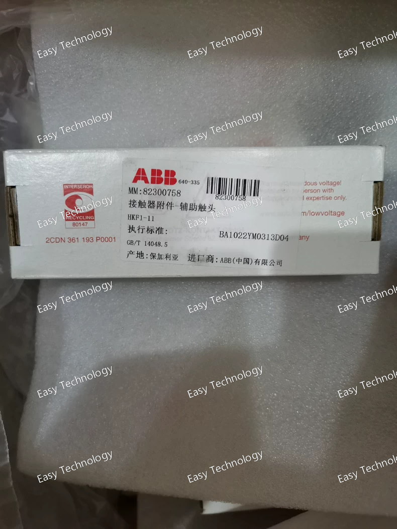
Technical Parameters General Product Type: Auxiliary contact block Model: HKF1‑11 Mounting Type: Front / top mount accessory for compatible starters and contactors Series / Compatibility: Suitable for modular control devices such as MS116, MS132, MS165 manual motor protectors and similar devices Contact Configuration: 1 × Normally Open (NO) + 1 × Normally Closed (NC) Electrical Ratings Rated Insulation Voltage (Ui): ~690 V Rated Operational Voltage (Ue): Suitable for control/auxiliary circuits up to industrial control voltages Rated Operational Current: Typical auxiliary circuit rating suitable for 1–6 A loads (control/feedback circuits) Rated Impulse Withstand Voltage (Uimp): Elevated to standard auxiliary device limits Contact Type: Silver‑based (or equivalent) industrial contact material Mechanical Terminal Connection: Screw terminal type Installation Orientation: Front / top mounting onto starter body Mechanical Life: High cycle capability for frequent auxiliary feedback operations Contact Actuation: Operates with main starter contacts Performance Switching Frequency: Designed for auxiliary control switching load cycles Compatibility With Motor Protection: Works alongside overload/trip feedback and interlock functions Physical & Dimensions Compact Modular Design: Space‑efficient mounting Weight: Lightweight accessory Construction: Durable industrial‑grade plastic and metal parts for robust panel use Environmental Operating Temperature Range: Typical industrial ambient temperatures Pollution Degree: Designed for typical industrial environments Ingress Protection: IP20 at terminals; front mounting in panel can offer additional protection Applications Adding auxiliary feedback to manual motor starters Providing interlocking contacts for control logic circuits Status signaling to PLCs and control systems Enhancing control panel logic with NO/NC feedback Use in motor control centers and industrial automation panels
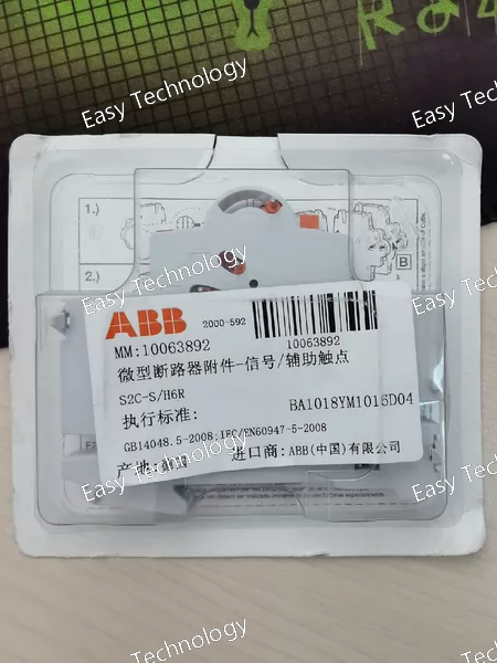
Technical Parameters General Product Type: Auxiliary / signal contact accessory Model: S2C‑S/H6R Compatibility: Designed for use with ABB System Pro M Compact devices including miniature circuit breakers (e.g., S200, S200M, S200P, S200S), SN201 series, RCCBs (F200), and RCBOs (DS201, DS202C) Mounting Position: Right side of main protective device Selector Function: Option to indicate either device contact position or fault condition Contact Configuration Contact Type: Auxiliary contact for status signaling Contact Changeover Selector: Changeover indication mode (breaker position vs. fault signal) Typical Output: Signal suitable for control circuits (wired back to PLC, indicator lamp, alarm panel, etc.) Electrical Ratings Rated Current: Suitable for auxiliary loads (control/indication) — typically up to 6 A Rated Voltage: Compatible with control voltage ranges up to approx. 250 V AC / 110 V DC (control/auxiliary signaling circuits) Coil / Switching Duty: Designed for AC‑12 / DC‑12 utilization categories (control and signaling use) Mechanical & Installation Mounting: Snap‑on / side‑mounted onto breaker body Terminal Connections: Screw terminals for secure interconnection of control/indicator wiring Number of Contacts: One auxiliary contact with selector function for status feedback Physical Width: ~8.8 mm Height: ~85 mm Depth: ~69 mm Weight: Lightweight compact accessory Construction: Durable industrial plastic and metal components for panel use Environmental Operating Temperature Range: Suitable for standard industrial ambient conditions Pollution Degree: Typical for control panels and distribution boards Applications Remote signal of breaker ON/OFF/trip status Feedback to PLC or automation systems Activation of alarm circuits on fault condition Control panel status indication lamps and annunciators Enhanced safety/monitoring of protective devices
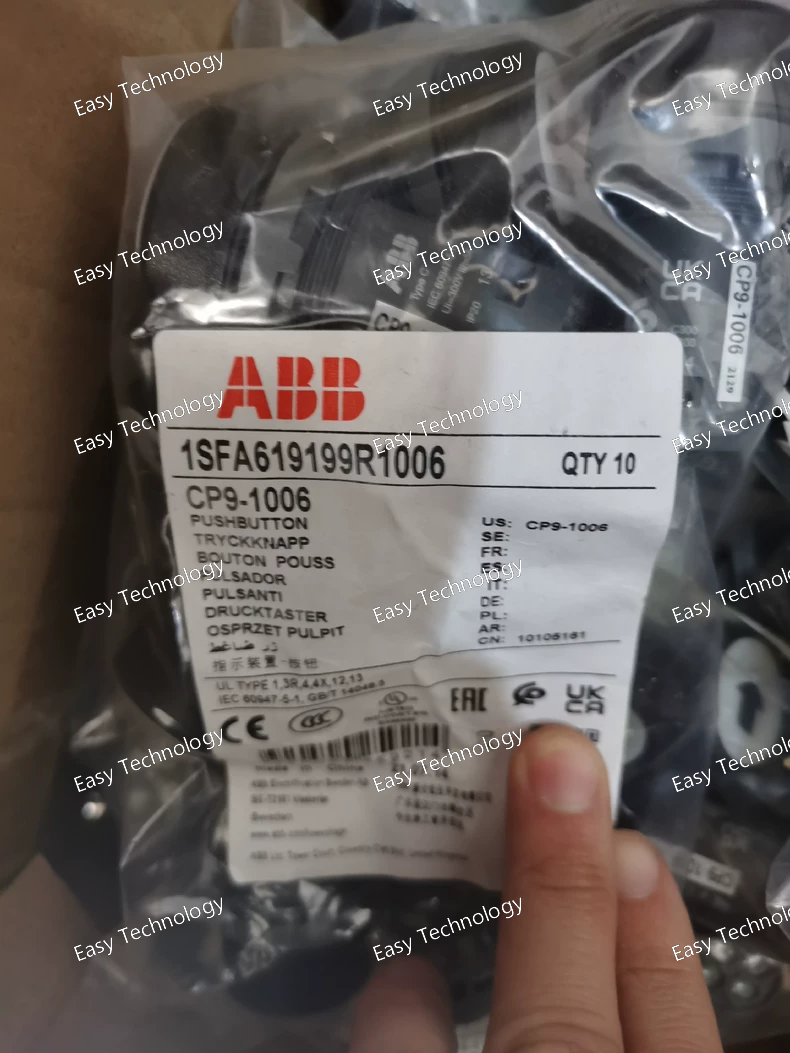
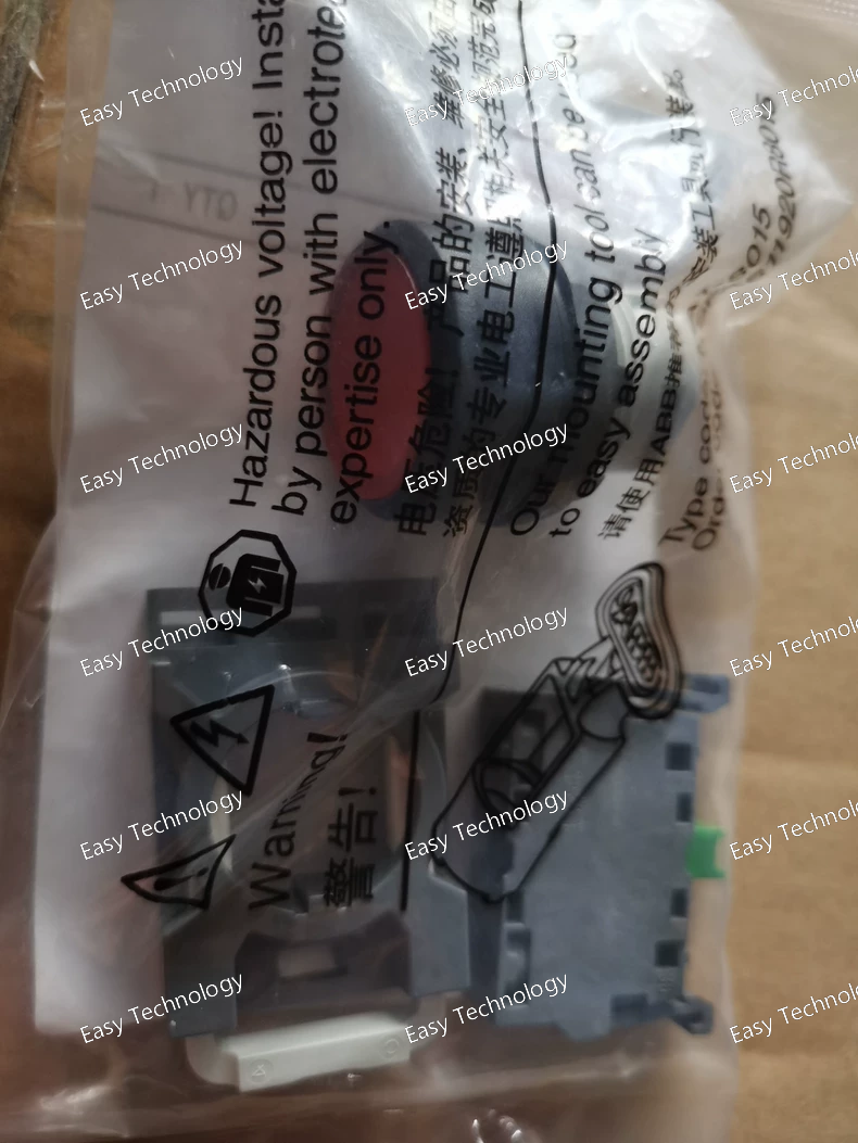
Technical Parameters General Product Type: Industrial pushbutton switch Model: CP9‑1006 Series: CP9 compact pilot devices Actuator Style: Round raised (mushroom) pushbutton Actuator Color: Green Operation Type: Momentary (spring‑return) Illumination: Non‑illuminated Panel Cut‑out Diameter: 22 mm standard Contact Configuration Normally Open (NO): 1 Normally Closed (NC): 1 Contact Form: 1 NO + 1 NC Contact Function: Changeover actuation during push Electrical Ratings Rated Insulation Voltage: Up to ~300 V Rated Operational Voltage: Up to ~300 V AC/DC Rated Operational Current (AC‑15): up to ~1–2 A at 220–240 V AC Rated Operational Current (DC‑13): up to ~0.2–0.3 A at 24–125 V DC Electrical Life: Designed for frequent switching in control circuits Mechanical & Durability Mechanical Life: Up to ~500,000 operations Terminal Type: Screw clamp terminals Connection Capacity: Suitable for solid or stranded conductors Housing Material: Durable industrial‑grade plastic Environmental & Protection Protection Rating (Front): High level of dust/water resistance when installed (e.g., IP66/IP67/IP69K) Protection Rating (Terminals): IP20 Operating Temperature: Approx. –25 °C to +70 °C Storage Temperature: Approx. –40 °C to +85 °C Pollution Degree: Suitable for industrial environments Physical/Dimensions Approximate Dimensions: Width/Height: ~30 × 30 mm (body) Depth (behind panel): ~55 mm Weight: Lightweight, typical pilot device mass Applications Start/Stop and control input in machinery panels Manual control in automation systems Operator station signaling and command buttons Control logic loops in industrial panels Interface for PLC and control circuits
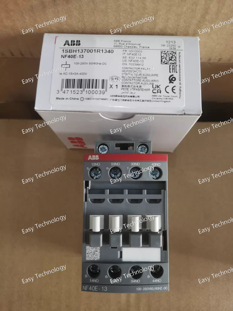
Technical Parameters General Product Type: Contactor relay / auxiliary contactor Model: NF40E‑13 Series: NF relay series Number of Poles / Contacts: 4 × Normally Open (NO) Mounting: DIN‑rail or screw mounting in control panels Terminal Type: Screw terminals Housing Design: Block‑type compact relay Weight: ~0.27 kg Operating Ambient Temperature: Approximately −40 °C to +70 °C Control / Coil Rated Control Supply Voltage (Uc): 100 – 250 V AC/DC (single wide range coil) Rated Frequency: 50 / 60 Hz for AC coil operation Control Circuit Compatibility: AC or DC operation without separate coil changes Electrical Ratings Rated Insulation Voltage (Ui): ~690 V Rated Operational Voltage: Auxiliary circuit circuits up to 690 V Conventional Free‑air Thermal Current (Ith): 16 A (free‑air at 40 °C) Rated Operational Current (AC‑15): ~6 A @ 24 / 127 V AC ~4 A @ 220 / 240 V AC ~3 A @ 400 / 440 V AC ~2 A @ 500 / 690 V AC Rated Operational Current (DC‑13): ~6 A @ 24 V DC ~2.8 A @ 48 V DC ~1 A @ 72 V DC ~0.55 A @ 125 V DC ~0.27 A @ 250 V DC ~0.15 A @ 400 V DC ~0.13 A @ 500 V DC ~0.10 A @ 600 V DC Performance & Switching Rated Impulse Withstand Voltage (Uimp): ~6 kV Rated Short‑time Withstand Current (Icw): ~140 A for 0.1 s ~100 A for 1 s Maximum Electrical Switching Frequency: ~1200 cycles/hour (AC‑15) ~900 cycles/hour (DC‑13) Maximum Mechanical Switching Frequency: ~6000 cycles/hour Mechanical & Connection Connecting Capacity: Flexible conductor with ferrule: ~0.75 … 2.5 mm² Rigid conductor: ~1 … 2.5 mm² Wire Stripping Length: ~10 mm Tightening Torque: Standard industrial terminal torque (approx. 1.2 N·m) Environmental & Protection Protection Rating: Terminals: IP20 Panel installation provides typical front panel protection Pollution Degree: Suitable for industrial environments Maximum Operating Altitude: Up to ~3000 m without derating Applications Switching of auxiliary and control circuits in automation panels Interface between control logic (PLC, control switches) and load circuits Signal switching in industrial machinery and power systems Pilot duty and control relay roles in electrical panels
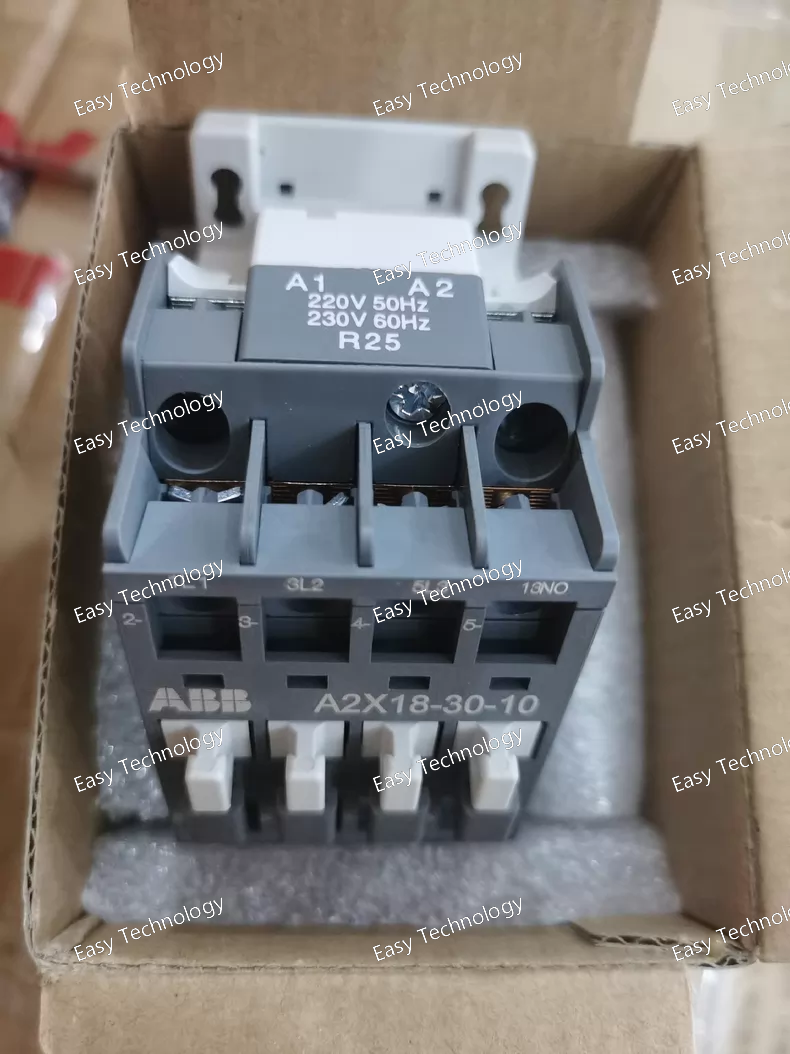
Technical Parameters General Product Type: AC contactor Model: A2X18‑30‑10 Series: A2X18 Poles: 3 main poles Auxiliary Contacts: 1 NO (built-in) Control Type: Electromagnetic AC coil Mounting: DIN rail or panel (block type) Modular Design: Supports add-on auxiliary blocks and accessories Electrical Ratings Rated Operational Current (AC‑3): ~25 A at 400 V AC Rated Operational Current (AC‑1): ~25 A Rated Insulation Voltage (Ui): ~690 V AC Rated Impulse Withstand Voltage (Uimp): ~6 kV Control Circuit Voltage (Coil): Depends on variant (24 V, 48 V, 110 V, 220–230 V, 380–400 V AC) Coil / Control Coil Frequency: 50 / 60 Hz Coil Variants: 24 V, 48 V, 110 V, 220–230 V, 380–400 V AC Performance Motor Rated Operational Power (AC‑3): ~7.5 kW at 400 V AC Switching Capacity: Suitable for industrial power switching operations Electrical Endurance / Life: High Mechanical Endurance: High Control & Terminals Terminal Type: Screw terminals Contact Material: Industrial alloy Expansion: Front or side-mount auxiliary contact blocks can be fitted Physical & Environmental Compact Block Design: Space-efficient for panels Operating Temperature: Standard industrial range Pollution Degree: Suitable for industrial environments Applications Motor control starters Industrial automation systems Pump, fan, and compressor control General AC load switching in control panels Integration with overload relays and starter assemblies
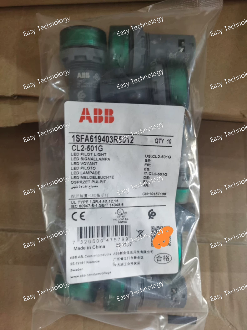
Technical Parameters General Product Type: Illuminated pilot light Model: CL2‑501G Series: Compact pilot devices Lens Color: Green Indicator Type: LED (integrated) Mounting: Panel mount (standard 22 mm cut‑out) Shape: Circular flat lens design Electrical Ratings Rated Supply Voltage: 12 V DC Rated Current / Consumption: ~16 mA at 12 V DC Light Source: Integrated LED (no replaceable bulb) Rated Insulation Voltage: Suitable for low‑voltage control circuits Mechanical & Connection Terminal Connection: Screw terminals Base Type: BA9s style or similar suitable mounting interface Service Life: ≥ 50,000 hours typical LED life Lens Material: Durable polycarbonate or equivalent plastic Environmental & Protection Front Protection Rating: IP66 / IP67 / IP69K (high resistance to water and dust ingress at front) Terminal Protection: IP20 NEMA / Enclosure Ratings: NEMA 1 / 3R / 4 / 4X / 12 / 13 Operating Ambient Temperature: ~ –25 °C to +70 °C Storage Temperature: ~ –40 °C to +85 °C Pollution Degree: Suitable for typical industrial environments Physical Panel Cut‑out Diameter: 22 mm Dimensions (Approx.): ~30 × 30 × 52 mm Net Weight: ~0.018 kg Applications Visual indication of equipment status, faults, or power presence Control panels and operator stations Industrial automation systems Machine interfaces in manufacturing environments OEM equipment signaling
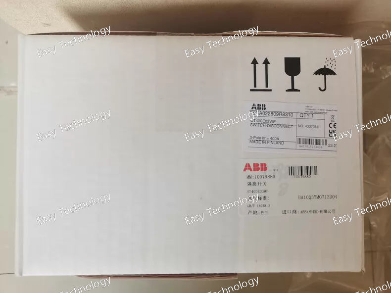
Technical Parameters General Product Type: Manual load switch / Switch‑Disconnector Model / Variant: OT400E03WP Poles: 3 (three‑pole) Mounting: Base mounting, front operated Actuator: Black operating handle with shaft included Padlock Capability: Can be locked in OFF position Device Construction: Enclosed fixed installation type Electrical Ratings Rated Continuous Current (Iu): 400 A Rated Operational Voltage (Ue): up to 1000 V AC Rated Operational Current (AC‑21A/AC‑22A/AC‑23A): 400 A across typical low‑voltage AC systems Rated Operational Power (AC‑23A): ~132 kW at 220–240 V ~230 kW at 400–415 V ~280 kW at 500 V ~400 kW at 690 V Rated Insulation Voltage (Ui): 1000 V Rated Impulse Withstand Voltage (Uimp): 12 kV Rated Short‑Time Withstand Current (Icw): ~15 kA for 1 s Short‑Circuit Making Capacity (Icm): ~65 kA (at 690 V) Conditional Short‑Circuit Current (Icn): up to ~100 kA with proper fusing Mechanical & Connections Number of Switches: 1 Terminal Type: Lug/bolt connections Wide Phase Spacing: Yes (larger phase separation for safer high‑current routing) Operating Mode: Front operated Distance Between Phases: Standard widened spacing Mechanical Durability: Designed for long service life with frequent operation Physical & Environmental Protection Rating: Front IP00 (terminals not finger‑safe without enclosure) Pollution Degree: Industrial (Pollution degree 3) Handle Color: Black Operating Temperature: Standard industrial ambient range Installation Location: Suitable for distribution boards and equipment panels Standards Compliance Designed to meet IEC 60947‑3 (Low‑voltage switch‑disconnector standards) Applications Main power isolation in electrical panels Maintenance and service disconnect in power distribution Load switching for motors, feeders, and general circuits Use in industrial, commercial, and utility power systems
 TEL: Grace +86 13600179521
  Mail: info@hongkongeasy.com jilineasyyi@outlook.com
 Q Q:615739355
 ADDRESS:Unit 12, 20th Floor, Good View Commercial Centre, 2-16 Garden Street, Mong Kok, Hong Kong
 whats app


