
Industrial Controller
All product are in stock,guaranteed delivery within 3-7 days.


PRODUCT
PICTURE
BRAND
DESCRIBE
STOCK
DOWNLOAD
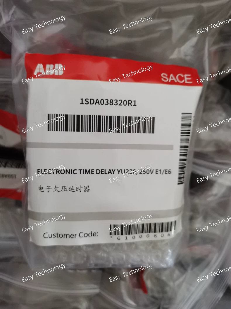
Key Features Time Delay Function: Adds an adjustable electronic delay before breaker opening on undervoltage or specified trigger. Compatible with Multiple Breaker Series: Fits a range of ABB breakers including the Tmax XT and Emax families. AC/DC Supply: Designed to operate on a 220 – 250 V AC/DC coil or control voltage. Accessory Module: Used as an add‑on to extend protective functionality of circuit breakers. Compact Design: Sized to integrate with breaker accessories in panel installations. DIN/Panel Friendly: Dimensions and mounting suit standard electrical enclosure layouts. Electrical Ratings Rated Control Supply Voltage: 220 – 250 V AC/DC — works with both AC and DC control supplies. Input Type: Designed for AC and DC voltage sensing used in timing logic. Timing Function: Electronic delay between voltage condition and release action (helps avoid unwanted trips). Integration: Works with other breaker control accessories to coordinate undervoltage and delayed release behavior. Mechanical & Environmental Module Width: Approximately 150 mm. Height: Approximately 60 mm. Depth: Approximately 200 mm. Weight: Around 0.25 kg. Installation: Connected as an accessory to compatible breakers; panel or accessory rail mounting typical. Ambient Conditions: Suitable for standard industrial panel environments. Functional Use This electronic time delay unit is used to delay breaker opening in response to certain voltage conditions, reducing the chance of unnecessary trips during short disturbances. For example, in motor control centers or distribution panels, it helps maintain continuity through transient dips, while still providing protective action if the condition persists. Typical Applications Low‑voltage power distribution panels where transient voltage drops are common. Motor control and feeder circuits requiring controlled undervoltage response. Industrial automation systems needing enhanced coordination between supply conditions and breaker operation. Enhancing protective functionality of ABB Tmax and Emax circuit breakers by adding timing logic.
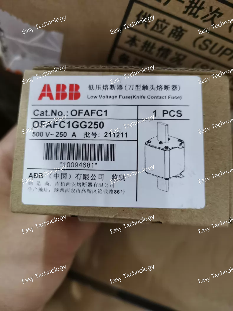
Key Features Fuse Type: gG general‑purpose HRC fuse link — suitable for both overload and short‑circuit protection. Format: DIN‑type fuse link for use in standard fuse holders or switch‑fuse disconnect assemblies. High Breaking Capacity: Designed to safely interrupt high fault currents and protect connected equipment. Replaceable Link: The fuse element can be replaced after a fault trip, minimizing downtime. Compact Construction: Space‑efficient design for integration into modular switchgear and panels. Electrical Ratings Rated Current: 250 A — continuous current rating for protecting circuits. Rated Operational Voltage: 690 V AC — suitable for low‑voltage three‑phase systems. Utilization Category: gG — general purpose, covering conductor and equipment protection duties. Standards Compliance: Designed in accordance with international low‑voltage fuse standards for HRC links. Mechanical & Physical Fuse Size: NH1 / DIN size 1 — compact form factor suited to DIN‑rail fuse bases. Housing: Robust metallic/ceramic body engineered for reliable operation in power circuits. Terminal Style: Knife blade or blade contacts to fit compatible holders securely. Environmental Operating Conditions: Suitable for standard indoor electrical panels and distribution cabinets. Installation: Installed inside an appropriate fuse holder or disconnect switch mounting, providing safe isolation and fault interruption. Typical Applications Low‑voltage power distribution protection in industrial and commercial systems. Motor feeder and transformer protection against overloads and short circuits. Control panel and switchboard protection when paired with DIN‑type fuse holders. General circuit protection where HRC performance is required.
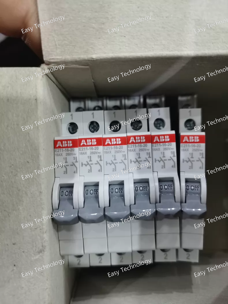
Key Features Switch Type: ON‑OFF isolator / manual control switch — used to manually connect or disconnect circuits. Pole Configuration: 2‑pole design for switching both poles of a circuit. Contacts: Two normally open (NO) contacts — closes when switched ON. Compact Module: Slim profile suitable for modular panel mounting (approx. half‑module width). DIN‑Rail Ready: Designed for installation on standard DIN rails inside electrical panels. Clear ON/OFF position indication on the actuator for visual status of the switch. Electrical Ratings Rated Current: 16 A continuous load capacity suitable for general control and power circuits. Rated Operational Voltage: Designed for use up to 250 V / 400 V AC in typical low‑voltage systems. Rated Frequency: Usable on both 50 Hz and 60 Hz AC systems. Switching Category: Suitable for switching mixed resistive and inductive loads with moderate overloads. Short‑Circuit Breaking Capacity: Capable of interrupting fault currents up to 3 kA in typical installations. Rated Impulse Withstand Voltage: Provides robust dielectric performance to withstand voltage transients. Mechanical & Environmental Poles: 2 for switching of both line conductors. Protection Rating: IP20 at terminals when mounted inside an enclosure. Operating Temperature Range: Suitable for typical electrical panel ambient conditions. Mounting: Snap‑on DIN rail or panel mounting as part of modular control assemblies. Physical & Installation Module Width: Approx. 9 mm (half‑module) for space‑efficient panel installation. Dimensions: Compact form factor to fit standard control panel layouts. Terminals: Screw‑type or clamp connections for secure conductor installation. Weight: Lightweight design for easy handling and integration. Typical Applications Manual control of auxiliary circuits such as indicators, lights, fans, or pumps. ON‑OFF control input in control panels and distribution boards. Switching of electrical loads in industrial machines and automation systems. Panel‑mounted isolator switch for maintenance and safety applications.
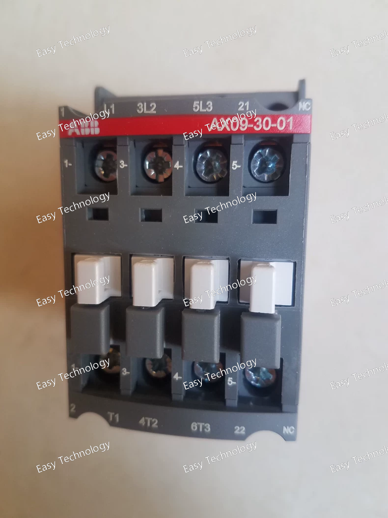
Parameters Main Circuit Ratings Rated Operational Voltage: Up to 690 V AC across the main power contacts. Rated Operational Current (AC‑1): Suitable for general switching (e.g., ~22 A at 690 V or ~22 A at 220–240 V). Rated Motor Duty (AC‑3): Typical duty current ~9 A for 220–440 V motors; lower at higher voltages. Rated Power (AC‑3): Several kilowatts depending on supply voltage (e.g., ~2–5.5 kW range). Rated Insulation Voltage: ~690 V. Rated Impulse Withstand Voltage: ~6 kV (control and main circuits). Control / Coil Coil Rating: 110 V AC control supply — optimized for use on 50 Hz or 60 Hz mains within the rated range. Contact Ratings Auxiliary Contact: One auxiliary changeover output useful for control feedback. Switching Categories: AC‑15: Control circuit switching at moderate currents (e.g., few amps). DC‑13: Lower DC load switching capability. Switching Performance Electrical Switching Frequency: Typical rates for control and power contacts (hundreds to over one thousand operations per hour under rated categories). Mechanical Switching Frequency: Higher mechanical life frequency for repeated operations. Mechanical & Environmental Poles: 3 main power poles plus auxiliary contacts. Operating Environment: Designed for standard industrial ambient conditions (wide temperature range typical for control equipment). Mounting: Compact enclosure suited for panel or component mounting in control cabinets. Physical Dimensions & Installation Footprint: Slim profile for dense panel layouts. Weight: Lightweight, facilitating easy mounting and replacement. Terminals: Screw terminals for both power and control wires. Typical Applications Motor starters and soft starters (as the main contactor). Control panels for pumps, fans, compressors, and conveyors. General power switching in automation and industrial installations. Integration with overload relays and control logic systems.
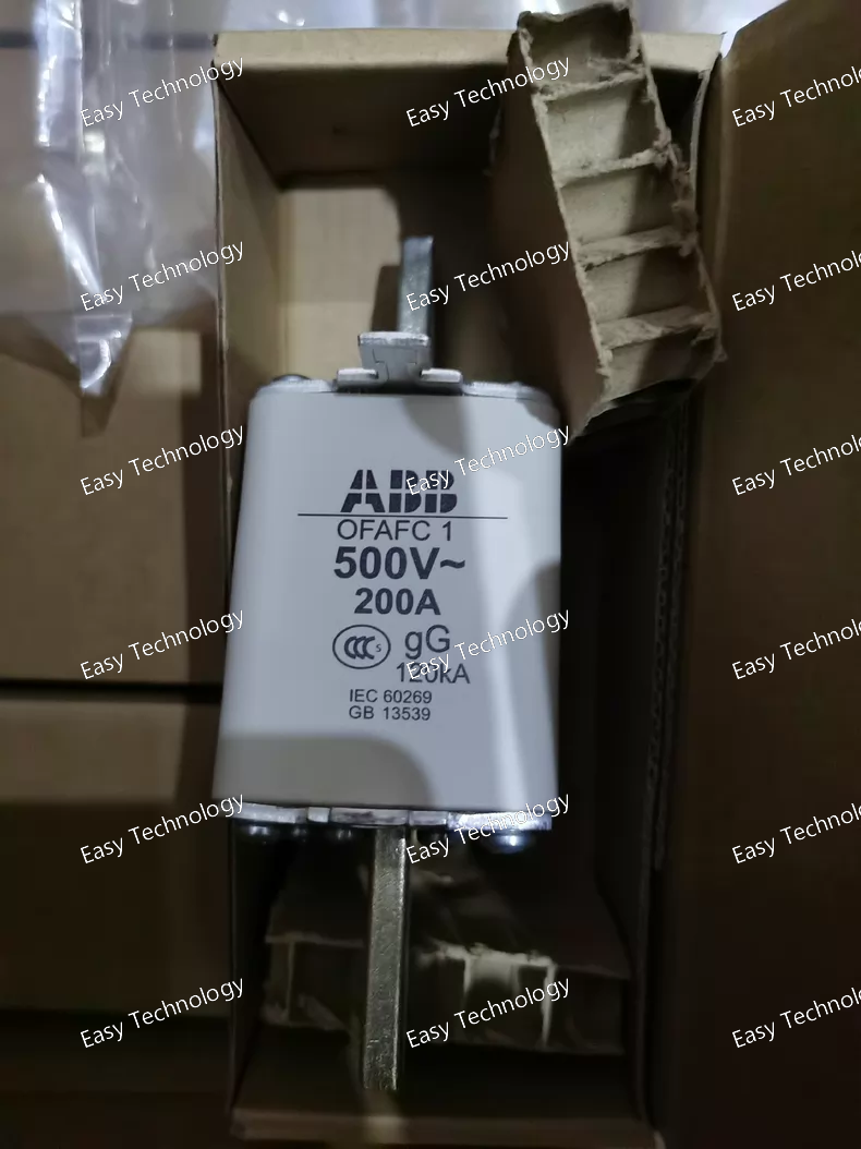
Parameters Nominal Fuse Current: 200 A — protects circuits with continuous current up to this value before blowing. Utilization Category: gG — general purpose protection for overload and short circuit in power distribution. Rated Operational Voltage: Up to 690 V AC for three‑phase networks or 500 V AC in some configurations. Breaking Capacity: High fault current interruption capability suited to industrial electrical installations. Standards: Designed to meet relevant international low‑voltage fuse standards for HRC protection. Mechanical & Physical Fuse Size: DIN‑type HRC link with compact rectangular profile for modular assemblies. Construction: Metal and ceramic/fuse element housing engineered for safe, high‑energy fault interruption. Replacement: Plug‑out/plug‑in style fuse link for easy maintenance and replacement within compatible holders. Environmental & Operational Operating Environment: Suitable for installation inside electrical enclosures, distribution boards, motor control centers, and switchgear. Ambient Conditions: Designed to operate over typical industrial ambient temperature ranges. Installation: Used with appropriate DIN‑type fuse holders or switch‑fuse disconnect devices for secure, code‑compliant installations. Typical Applications Primary overload and short‑circuit protection in low‑voltage power distribution networks. Protection of motors, transformers, and feeders in industrial control panels. Overcurrent protection in switchboards, motor control centers (MCC), and distribution panels. Integration with fusible disconnect switches to provide combined isolation and protection.
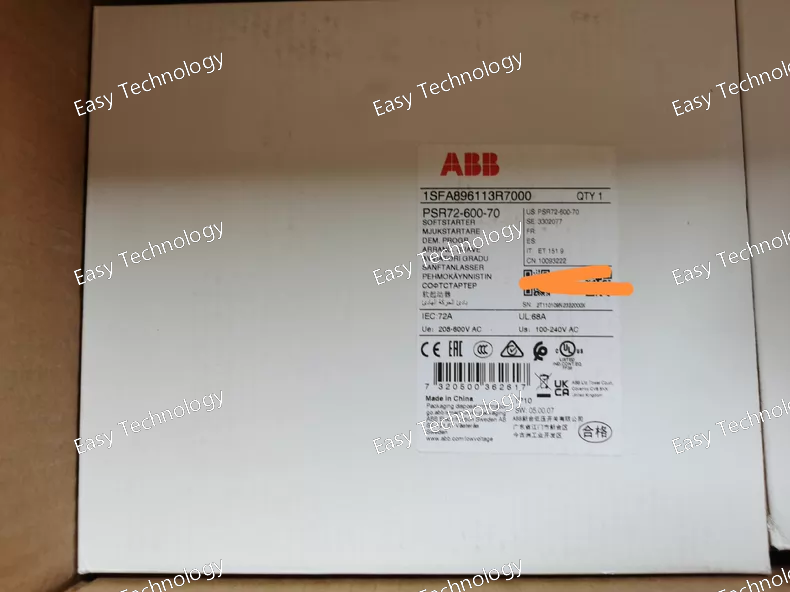
Parameters Main Circuit Rated Operational Current: 72 A (continuous). Rated Operational Voltage: 208 – 600 V AC three‑phase. Rated Power (Typical): Approx. 22 kW at 230 V Approx. 37 kW at 400 V Approx. 45 kW at 500 V Control Circuit Control Supply Voltage: 100 – 240 V AC (50/60 Hz). Rated Frequency: 50/60 Hz. Control Logic: Front‑panel potentiometers for adjusting start/stop ramp times. Outputs Auxiliary Relays: RUN — indicates the motor is running. TOR — indicates the end of the ramp (full speed reached). Relays typically provide normally open (NO) contact outputs for integration with external control or indicator circuits. Performance & Adjustments Start Ramp Time: Adjustable (typically 0 – 20 s) to control acceleration. Stop Ramp Time: Adjustable (typically 0 – 20 s) for controlled deceleration. Voltage Control: Enables smooth ramping of applied voltage to reduce torque shock. Mechanical & Environmental Mounting: Designed for control cabinet installation; compact footprint for efficient panel layout. Operating Temperature: Suitable for typical industrial ambient conditions. Protection Rating: Basic industrial protection; intended for installation inside an enclosed panel. Physical Dimensions Width: Approximately 180 mm Height: Approximately 220 mm Depth: Approximately 70 mm Weight: Around 2.1 kg Typical Applications Starting and stopping three‑phase induction motors such as pumps, fans, compressors, and conveyors. Applications where reduced mechanical wear and lower electrical peak currents are desired. Motor control systems in manufacturing, processing plants, and HVAC installations.
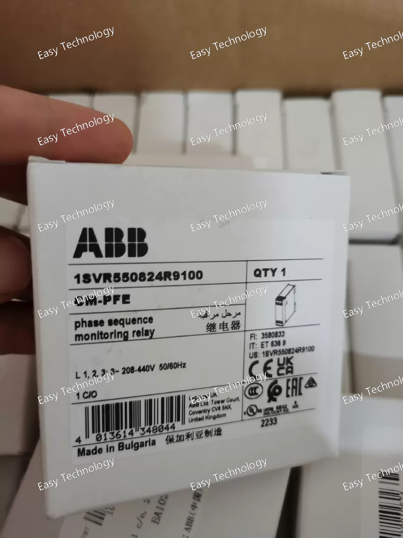
Parameters Rated Control Supply Voltage: 208 – 440 V AC across phases (measuring voltage equals control supply). Voltage Measuring Range: Three‑phase line‑to‑line input 208 – 440 V AC. Rated Frequency: 50/60 Hz operation. Output Contact Configuration: 1 changeover (SPDT) contact. Contact Rating: Typically suitable for control duty, e.g., switching up to ~250 V AC at moderate current levels (pilot duty load). Control Logic: Closed circuit principle — contact changes state when monitored conditions are met/failed. Delays: Brief built‑in start‑up and trip delays (~500 ms) to prevent nuisance tripping during normal power fluctuations. Mechanical & Environmental Mounting Footprint: Slim module (approx. ~22.5 mm width) for panel or DIN‑rail mounted sockets; installs alongside other control devices. Operating Ambient: Designed for typical electrical cabinet/panel environments. Terminal Interface: Screw clamp terminals for power and load wiring. Mechanical Durability: Rated for long service life in industrial control applications. Function Summary The CM‑PFE monitors the presence, order, and continuity of all three phases in an AC supply. If phase sequence is wrong or any phase is lost, the relay detects the fault and changes the state of its output contact. This output can then be used to disconnect equipment, trigger alarms, inhibit starts, or inform control logic to prevent damage. Typical Applications Motor protection circuits to prevent incorrect rotation due to wrong phase sequence. Control panels where phase integrity is required before allowing operation of heavy loads. Industrial automation systems requiring reliable phase monitoring. Distribution systems to detect and respond to phase loss or incorrect phase sequence.
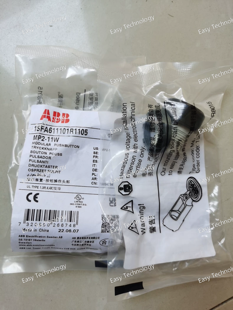
Parameters Electrical Illumination: Integrated illumination (white LED or lamp) — provides visual indication when activated. Contact Blocks: Not included — must be installed separately to provide electrical switching. Control Voltage for Illumination: Determined by the selected lamp/LED module. Rated Insulation & Withstand: Compatible with standard low‑voltage control circuits. Mechanical & Environmental Operator Function: Maintained — the pushbutton stays engaged until manually changed. Operating Temperature: Approximately –25 °C to +70 °C ambient. Storage Temperature: Approx. –40 °C to +85 °C. Mechanical Durability: Designed for a high number of actuation cycles. Protection Ratings: Front Face: High ingress protection when mounted — resistant to dust and water ingress. Terminals: Basic touch protection (IP20) when installed within an enclosure. Physical Dimensions Width: ~29 mm Height: ~29 mm Depth: ~33 mm Panel Cut‑out Diameter: 22 mm standard. Weight: Lightweight, compact pilot‑device design. Typical Applications Human‑Machine Interfaces (HMIs) for machine controls and panels. Status indication and manual control feedback in automation systems. PLC or contactor control circuits requiring maintained action with visual indication. Industrial process and equipment control panels that need illuminated pushbuttons.
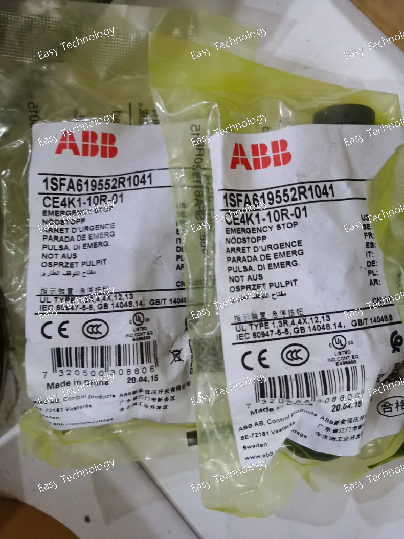
Parameters Electrical Contact Configuration: 1 Normally Open (1 NO) + 1 Normally Closed (1 NC) auxiliary contacts — allows both stop signal and feedback/status signal. Rated Operational Voltage: Suitable for a wide range of control voltages in low‑voltage AC/DC systems. Rated Current: Sized for typical control circuit duties up to moderate amperages (e.g., around 1–10 A depending on voltage). Insulation & Withstand: Meets general control‑circuit insulation and transient withstand requirements. Mechanical & Environmental Operation: Emergency stop with maintained latching — stays engaged until key release. Mechanical Durability: Designed for frequent use with a long operational life. Operating Temperature: Suitable for standard industrial panel ambient temperatures. Protection Ratings: Front Panel Protection: Offers resistance to dust and water ingress when correctly installed in compatible enclosures. Terminal Protection: Basic touch protection at terminals when installed inside an enclosure. Physical & Installation Panel Cut‑out: Standard 22 mm diameter pilot‑device hole. Actuator Diameter: 40 mm mushroom head for emergency actuation. Body / Bezel: Compact plastic housing designed for flush panel mounting. Terminal Type: Screw terminals for reliable conductor connection. Typical Applications Emergency stop inputs on industrial machinery and automation systems. Safety panels and operator interfaces requiring manual emergency control. Control logic circuits where both stop command and status feedback are needed. Human‑machine interface (HMI) stations for industrial equipment.
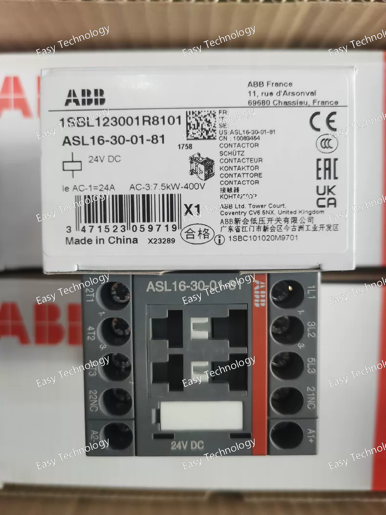
Parameters Rated Operational Voltage: Up to 690 V AC/DC on main circuit contacts. Control Coil Voltage: 24 V DC. Auxiliary Contact Configuration: 1 NC (normally closed). Main Contact Configuration: 3 NO (normally open). Control Circuit: DC coil with polarity (A1/A2) connections for reliable operation. Contact Ratings: Suitable for switching moderate currents typical in motors, heaters, and control loads. Mechanical & Performance Poles: 3 main poles plus 1 auxiliary NC contact. Mechanical Durability: High cycle life designed for industrial duty. Operate / Release Times: Fast actuation and release suitable for control logic requirements. Connection Type: Screw‑type terminals for secure wiring of main and auxiliary circuits. Mounting: Designed for panel or DIN‑rail integration via a compatible socket. Environmental & Protection Operating Temperature Range: Suitable for typical industrial ambient conditions. Storage Temperature Range: Suitable for standard handling and storage conditions. Terminal Protection: Basic touch protection at terminals when installed in an enclosure. Physical Dimensions Width: ~45 mm Depth: ~72.5 mm Height: ~68 mm Weight: ~0.28 kg Typical Applications Motor control: Switching three‑phase motors in automation and industrial systems. Control panels: Main switching element in contactor and starter assemblies. Automation systems: Interfacing low‑power DC control logic with high‑power AC circuits. General power control: Load switching in heating, lighting, and machine control circuits.
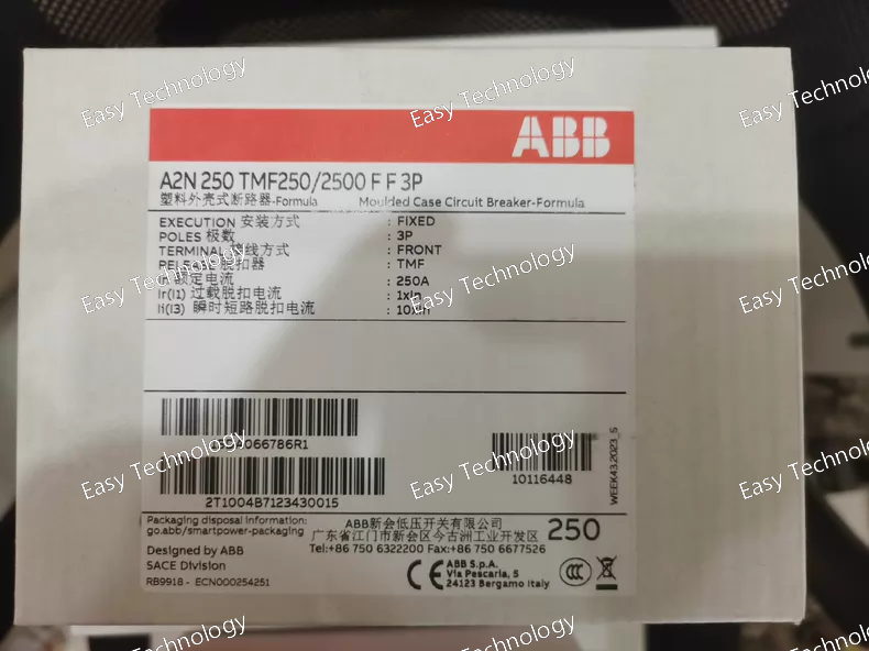
Key Features Type: 3‑pole molded case circuit breaker (fixed, non‑adjustable). Release Mechanism: Thermal‑magnetic (TMF) trip unit, combining thermal overload protection with instantaneous magnetic short‑circuit tripping. Front Terminals: Designed for easy connection and installation from the front of the breaker. Compact Design: Space‑saving dimensions suitable for control panels, distribution boards, or equipment protection. Electrical Ratings Rated Current (In): 250 A — nominal continuous current capacity of the main circuit. Control/Operational Voltages: Rated to interrupt under AC low‑voltage network conditions (AC) and DC loads as part of comprehensive protection. Insulation & Withstand: Designed for 690 V rated insulation and high impulse withstand voltage levels. Short‑Circuit Performance: Ultimate breaking capacity (Icu): High rated short‑circuit breaking performance suitable for industrial systems. Service short‑circuit breaking capacity (Ics): Substantial fraction of Icu, allowing effective protection and service continuity. Mechanical & Environmental Poles: 3 (three‑phase) — simultaneous protection of all three lines in a 3‑phase system. Mechanical Durability: Constructed to endure repeated manual switching and fault events. Operating Environment: Suitable for typical electrical cabinet environments in industrial and commercial installations. Physical & Installation Mounting: Panel or equipment mounting using fast clip/DIN rail or panel interface as designed for MCCBs. Terminals: Front access screw/clamp terminals provide secure connection for incoming and outgoing conductors. Compact Footprint: Reduced width profile compared to larger breaker frames, conserving panel space. Typical Applications Main and branch‑circuit protection in industrial and commercial power distribution. Motor feeder and equipment protection where short‑circuit and overload interruption are required. Control panels and switchgear needing compact, reliable circuit protection. Protection of generators, transformers, and distribution circuits in low‑voltage systems.
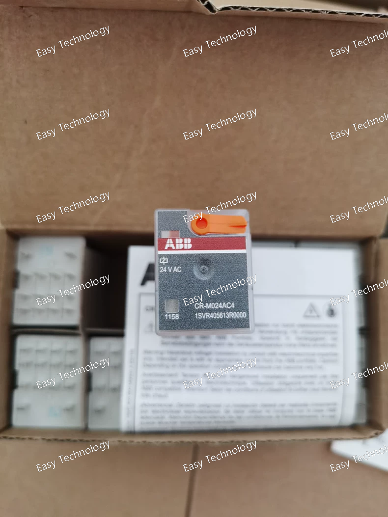
Electrical Parameters Rated Control Supply Voltage: 24 V AC. Rated Operational Voltage (Output Contacts): Up to 250 V AC. Contact Configuration: Four SPDT (changeover) contacts. Contact Ratings: 6 A switching capacity at 250 V AC per contact. Operational Current Categories: AC‑12: ~6 A at ~230 V AC AC‑15: ~1.5 A at ~120 V AC, ~1 A at ~230 V AC DC‑12: ~6 A at ~24 V DC DC‑13: ~2 A at ~24 V DC, ~0.1 A at ~250 V DC Rated Insulation Voltage: ~250 V between control and output circuits. Mechanical & Physical Dimensions: Width: ~21.2 mm Height: ~35.6 mm Depth: ~27.5 mm Weight: ~0.033 kg. Terminal Type: Flat‑pin connections for secure and compact socket wiring. Mounting: Relays plug into a socket that clips to a TH35 DIN rail. Environmental Operating Ambient Temperature: Approximately –40 °C to +55 °C. Storage Temperature: Typically down to –40 °C to +85 °C. Protection Rating: IP40 (touch‑protected terminals when mounted). Typical Applications Electrical Isolation & Signal Amplification: Between PLC/logic outputs and field devices. Control Panels: Switching auxiliary devices, indicators, and small loads. Automation Systems: Relay logic implementation, interlocking, and control signal distribution. Equipment Interfaces: Between low‑power control circuitry and higher voltage outputs.
 TEL: Grace +86 13600179521
  Mail: info@hongkongeasy.com jilineasyyi@outlook.com
 Q Q:615739355
 ADDRESS:Unit 12, 20th Floor, Good View Commercial Centre, 2-16 Garden Street, Mong Kok, Hong Kong
 whats app


