
Industrial Controller
All product are in stock,guaranteed delivery within 3-7 days.


PRODUCT
PICTURE
BRAND
DESCRIBE
STOCK
DOWNLOAD
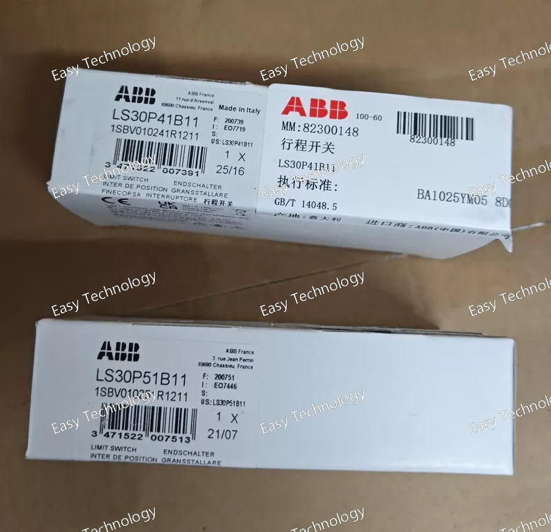
Key Features Type: Limit switch for mechanical position detection. Actuator: Polyamide roller lever (Ø18 mm) — ideal for detecting cam or mechanical travel. Contact Configuration: 1 Normally Open (NO) + 1 Normally Closed (NC) snap‑action contacts. Housing Material: Durable plastic with double insulation for robust industrial use. Degree of Protection: IP65 — dust tight and protected against water jets when installed properly. Mounting: Two M4 screw holes and PG13.5 cable entry for secure mounting and wiring. Electrical Parameters Rated Operational Voltage: Up to 400 V AC / 250 V DC. Rated Current: Up to 10 A in free air for control loads. AC‑15 Control Duty: 10 A at 24 V AC 5.5 A at 130 V AC 3 A at 230–240 V AC 1.8 A at 400 V AC DC‑13 Control Duty: 6 A at 24 V DC 0.6 A at 110 V DC 0.4 A at 250 V DC Rated Insulation Voltage (Ui): ~500 V (IEC); 600 V (UL/CSA). Rated Impulse Withstand Voltage (Uimp): ~6 kV. Mechanical & Environmental Operating Temperature: –25 °C to +70 °C ambient. Mechanical Durability: Millions of operations — high mechanical life. Electrical Switching Frequency: Up to ~3600 cycles/hour. Operating Head Movement: ~30° cam translation for reliable actuation. Physical Dimensions Body Width: ~30 mm. Height & Depth: Compact industrial profile ~106 × 45 mm. Weight: ~0.08–0.09 kg. Typical Applications Position sensing in automated equipment and machinery. End‑of‑travel detection on actuators, conveyors, and doors. Control system inputs for PLCs, relays, and safety interlocks. Machine safety and automation panels where mechanical motion needs electrical feedback.
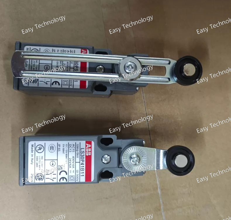
Key Features Type: Industrial limit switch for position detection. Actuator: Adjustable roller lever with an 18 mm diameter plastic roller for mechanical actuation. Contact Configuration: 1 Normally Open (NO) + 1 Normally Closed (NC) snap‑action contacts. Housing: Durable plastic enclosure rated for challenging industrial conditions. Ingress Protection: Protected against dust and water jets when mounted correctly (IP65). Connection: Single PG13.5 cable entry for wiring. Electrical Ratings Maximum Switching Current: 10 A for general use. Rated Operational Voltage: Up to 400 V AC. Up to 250 V DC. Contact Duty Examples: AC‑15 control duty e.g., ~10 A at 24 V AC, ~~3 A at 230 V AC, ~~1.8 A at 400 V AC. DC‑13 control duty e.g., ~~2.8 A at 24 V DC, ~~0.27 A at 250 V DC. Snap‑Action Contacts: Provide fast, positive electrical switching at actuation. Mechanical & Environmental Mounting: Two mounting holes allow secure attachment in machine frames or enclosures. Operating Temperature Range: Approximately –25 °C to +70 °C ambient. Mechanical Durability: Designed for thousands of cycles at industrial switching speeds. Body Material: Reinforced plastic (UL‑V0) for impact resistance and electrical insulation. Physical Dimensions Width: Approx. ~30 mm — compact form factor. Enclosure Size: ~30 × 53 × 30 mm (width × height × depth). Roller Lever: Adjustable length lever gives flexibility in actuation placement. Typical Applications Position sensing in automated conveyors, presses, and robotic guides. End‑of‑travel detection for sliding gates and linear actuators. Control logic inputs for programmable logic controllers (PLCs) and relay panels. Machine safety interlocks and limit detect loops.
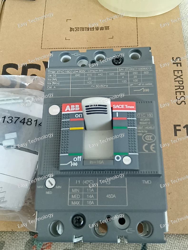
Key Features Circuit Breaker Type: Molded case circuit breaker (fixed, non‑adjustable trip). Poles: 3 (three‑phase) configuration for three‑phase systems. Trip Unit: Thermomagnetic (TMD) release — inherent overload and short‑circuit protection via thermal and magnetic mechanisms. Mounting: Fixed‑mount with front terminals for straightforward wiring. Industrial Use: Suitable for power distribution and protection in control panels and switchboards. Electrical Specifications Rated Current (In): 16 A — nominal continuous current capacity of the protection unit. Rated Operational Voltage: Up to 690 V AC (typical low‑voltage network). Up to 500 V DC (with appropriate pole series). Insulation Voltage (Ui): 800 V — withstands system insulation requirements. Impulse Withstand Voltage (Uimp): 8 kV — robust against transient voltage surges. Short‑Circuit Protection: Rated Instantaneous Short‑Circuit Setting (Ii): 450 A magnetic threshold. Breaking Capacities: Service and ultimate short‑circuit breaking capacities vary with voltage level (higher values at lower voltages, lower at higher voltages). Rated Frequency: 50/60 Hz operation. Rated Uninterrupted Current (Iu): 160 A — conductor thermal rating for the breaker frame. Performance & Endurance Electrical Durability: Designed for thousands of make/break cycles at rated load. Mechanical Durability: High operational life for repeated switching. Opening Characteristics: Fast response under specified overload and fault conditions. Mechanical & Installation Connection Type: Front screw terminals for secure conductor clamping. Compact Form Factor: Space‑efficient size for panel layouts. Weight & Size: Moderate footprint suitable for distribution boards and machine panels. Typical Applications Three‑phase circuit protection in industrial and commercial power distribution systems. Branch‑circuit safeguard for motors, feeders, transformers, and general loads. Protection in control panels and machinery electrical sections. Overload and short‑circuit protection where a basic, robust circuit breaker is needed.
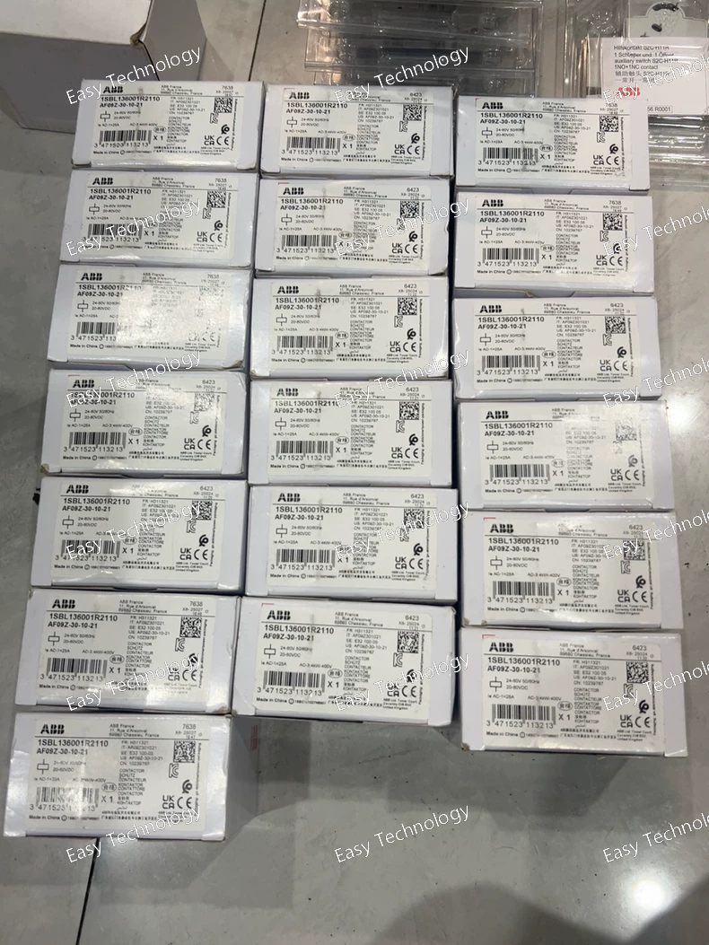
Key Features Contactor Type: 3‑pole power contactor with DC operated coil for switching three‑phase circuits. Control Coil Voltage: 24 V DC control coil for direct DC logic or PLC control. Auxiliary Contacts: Typically supplied without auxiliary contacts built in, but can accept add‑on auxiliary contact blocks. Compact Block Design: Space‑efficient footprint for control panels and motor controllers. Suitable For: Industrial motor control, general switching duties, and automation interfaces. Electrical Ratings Main Circuit Rated Operational Voltage: Up to 690 V AC for three‑phase loads (standard low‑voltage distribution). Rated Operational Current: AC‑3 (motor load): Typical values ~9 A at 220–500 V AC (varies by specific climate/standards). AC‑1 (general resistive loads): ~25 A at 690 V AC (limited by design). ABB Library Rated Control Voltage (Coil): 24 V DC — energizes the coil to close the main contacts. todaycomponents.com Control & Auxiliary Control Coil Type: DC coil with polarity marked terminals (A1+ / A2‑). Coil Consumption: Low DC coil consumption designed for efficient control circuits. Auxiliary Contacts: Use optional add‑on auxiliary blocks for status feedback. Mechanical & Environmental Number of Main Poles: 3 main power poles for three‑phase switching. Mechanical Life: Designed for thousands of mechanical cycles. Operating Temperature Range: Typical industrial ambient range (e.g., approx. –40 °C to +70 °C). Mounting: DIN‑rail or screw mounting inside control enclosures. Physical & Installation Connection Type: Spring or screw terminals depending on variant/holder. Compact Form Factor: Slim profile making it ideal for dense panel layouts. Weight: Lightweight for panel integration. Typical Applications Motor control: Starting/stopping three‑phase motors from a DC control source. Automation panels: Integrating AC power switching with DC logic outputs (e.g., PLC). Load switching: Fans, pumps, compressors, conveyors, and general AC loads up to rated current. Control systems: Systems requiring DC coil actuation with AC load switching.
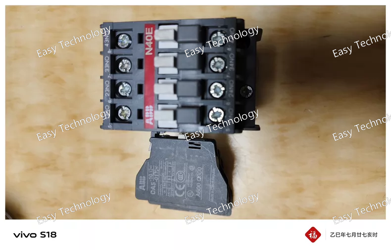
Key Features Accessory Type: Auxiliary contact block for contactors and relays. Pole Count: 1 pole — one auxiliary contact. Contact Configuration: 1 Normally Open (1 NO) contact — closes when the associated contactor energizes. Mounting Style: Front mounted on ABB contactor bodies. Connection: Screw‑type terminals for secure wiring. Expands control circuit capabilities without altering the main power path. Electrical Ratings Rated Operational Voltage: Up to 690 V AC. Rated Control Current (AC‑15): ~6 A at 24–127 V AC Up to ~2 A at 500–690 V AC Rated Frequency: 50 / 60 Hz. Utilization Category: AC‑15/DC‑13 for control circuitry (suitable for PLC inputs, indicator circuits, interlocks). Mechanical & Performance Operating Cycles: Designed for repeated switching — several thousand cycles per hour. Protection: Terminals touch‑protected to IP20 when installed inside an enclosure. Construction: Compact block for front‑mount integration with contactor assemblies. Physical & Installation Installation: Clips or bolts onto the front of an ABB contactor. Housing: Durable polymer body with clearly marked terminals. Terminals: Screw connections for control wiring. Typical Applications Control logic feedback: Signal to PLCs, relays, or indicator lights when the main contactor closes or opens. Interlocking: Electrical interlock schemes between contactors or stages of control. Automation systems: Expands functionality without modifying the main load circuit.
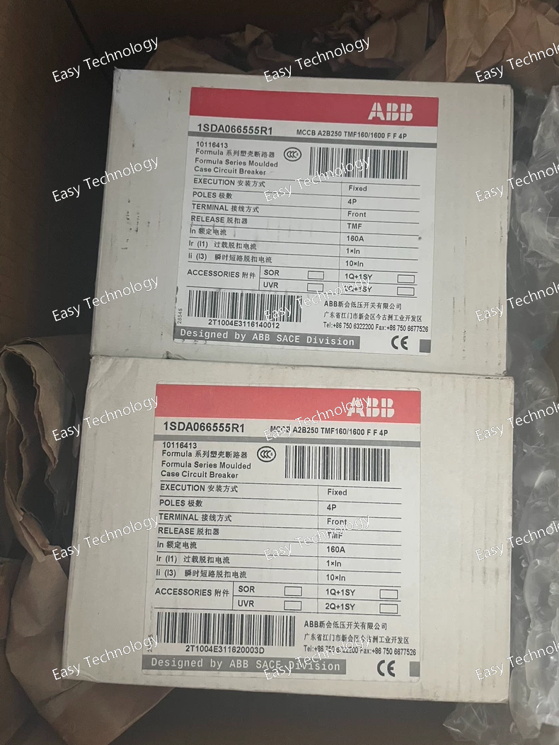
Key Features Circuit Breaker Type: 4‑pole molded case circuit breaker (MCCB) with fixed thermal‑magnetic trip unit. Protection Function: Combines thermal overload protection with instantaneous magnetic short‑circuit protection. Compact Design: Space‑efficient size suitable for distribution boards and control panels. Poles: 4 poles — protects four conductors simultaneously (three phases plus neutral). Front Terminals: Front‑accessible screw/clamp connections for easy wiring. Electrical Ratings Rated Current (In): 160 A — continuous current capacity of the main circuit. Rated Operational Voltage: Up to 550 V AC for AC power systems. Up to 250 V DC for DC systems. Rated Insulation Voltage (Ui): 690 V — insulation rating suitable for low‑voltage distribution systems. Impulse Withstand Voltage (Uimp): 6 kV, robust against transient voltage spikes. Rated Ultimate Short‑Circuit Breaking Capacity (Icu): Up to 25 kA at 240 V AC. Up to 18 kA at 380–415 V AC. Lower but substantial breaking capacity at higher voltages (e.g., ~15 kA at 440–480 V AC). DC interrupt capacity at 250 V is also provided with two poles in series. Rated Service Short‑Circuit Breaking Capacity (Ics): Typical service‑level breaking capabilities at common system voltages. Rated Uninterrupted Current (Iu): 250 A — applicable conductor thermal rating for the breaker frame. Mechanical & Durability Electrical Durability: Designed for approximately 4,000 load switching cycles. Mechanical Durability: Designed for around 10,000 mechanical operations. Opening Time: Fast internal tripping (e.g., ~15 ms under specified conditions). Power Loss: Low per‑pole power loss (e.g., ~9 W at rated conditions). Physical & Installation Configuration: Compact MCCB in standard industrial form factor. Mounting: Panel or switchboard fixed mounting with front‑terminal access. Weight & Footprint: Moderate weight and compact footprint ideal for modular distribution panels. Typical Applications Protection of three‑phase systems including motor feeders, distribution circuits, and equipment panels. Main and branch‑circuit protection in industrial plants and commercial installations. Control panel overcurrent protection for automation equipment.
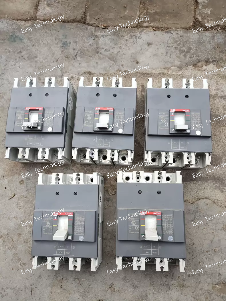
Key Features Circuit Breaker Type: Molded Case Circuit Breaker (MCCB) with fixed thermal‑magnetic trip unit — protects against overloads and short‑circuits. Frame Size: A2 — accommodates ratings from roughly 125 A up to 250 A. Poles: 1‑, 2‑, 3‑, or 4‑pole configurations for single‑phase and three‑phase systems. Mounting: Fixed, front terminal type — installs directly on panel back plates or distribution board backplanes. Trip Unit: Thermomagnetic with fixed thresholds, providing simple, ready‑to‑use protection. Compact Size: Smaller footprint compared to larger breaker families, helping save panel space. Electrical Ratings Rated Operational Current (In): Up to ~250 A continuous current capacity. Rated Insulation Voltage (Ui): Up to ~690 V AC. Rated Operational Voltage: Suitable for AC systems up to standard low‑voltage distribution levels (~550–690 V depending on the variant). Rated Impulse Withstand Voltage (Uimp): Approximately 6 kV transient withstand capability. Trip Characteristic: Thermomagnetic with fixed overload and instantaneous short‑circuit protection. Short‑Circuit Breaking Capacity: Robust interrupt rating suitable for general distribution panel duties. Mechanical & Environmental Durability: Engineered for a high number of mechanical and electrical operations over its service life. Operating Conditions: Suitable for typical electrical enclosure environments in industrial and commercial installations. Installation: Front‑accessible screw/clamp terminals for secure cable connections. Typical Applications Branch‑circuit protection in industrial and commercial distribution boards. Motor feeder and load protection in machinery panels. Control panel protective element for power circuits requiring reliable overload and short‑circuit interruption. General electrical safety protection in low‑voltage systems where basic fixed protection is required.
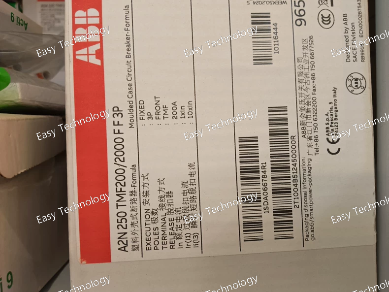
Key Features Circuit Breaker Type: Fixed molded case circuit breaker with thermomagnetic protection. Poles: 3 poles for three‑phase system protection. Trip Mechanism: Thermo‑magnetic (TMF) — combines thermal overload and instantaneous magnetic short‑circuit protection. Front Terminals: Easy front access for incoming and outgoing conductors. Compact Design: Space‑saving profile for panel and switchboard integration. Electrical Specifications Rated Current (Main Circuit): 200 A — continuous operating current capacity. Rated Operational Voltage: Up to 550 V AC and 250 V DC in low‑voltage systems. Rated Insulation Voltage: 690 V — withstands standard electrical insulation requirements. Rated Impulse Withstand Voltage (Uimp): 6 kV — robust against transient overvoltages. Rated Service Short‑Circuit Breaking Capacity (Ics): Example values: ~42.5 kA at 240 V AC; ~18 kA at 380–415 V AC; ~12.5 kA at 440–480 V AC; lower DC. Rated Ultimate Short‑Circuit Breaking Capacity (Icu): Example values: ~85 kA at 240 V AC; ~36 kA at 380–415 V AC; ~25 kA at 440–480 V AC; lower DC. Rated Uninterrupted Current (Iu): 250 A — maximum conductor thermal rating. Mechanical & Endurance Electrical Durability: Designed for ~4,000 switching cycles under load. Mechanical Durability: Designed for ~10,000 mechanical operations. Opening Time: Fast internal response (~15 ms) under specified conditions. Environmental & Standards Standards Compliance: Built to international low‑voltage protection standards. Operating Conditions: Suitable for typical control panel and distribution board environments. Physical & Installation Mounting: Panel or enclosure installation with front‑accessible terminations. Compact Dimensions: Efficient size for space‑constrained installations. Terminal Type: Screw/clamp‑style front connections. Typical Applications Low‑voltage power distribution in industrial and commercial panels. Branch and feeder protection for motors, transformers, and loads. Control and automation panels where robust protection and compact size are key. General safety overcurrent protection in three‑phase systems.
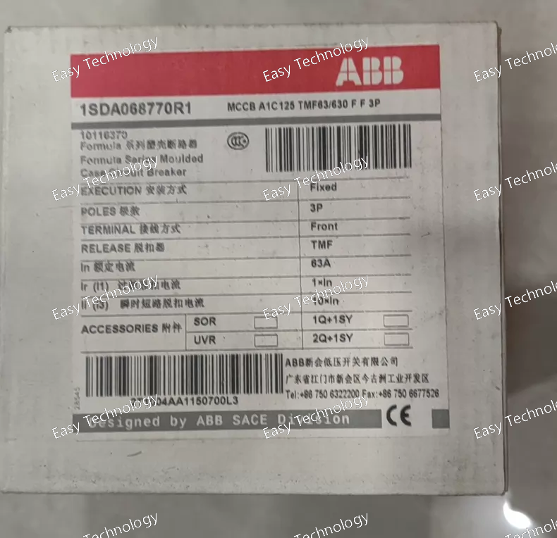
Key Features Circuit Breaker Type: Fixed molded case circuit breaker with thermomagnetic protection. Poles: 3 poles for three‑phase circuit protection. Trip Mechanism: Thermal‑magnetic (TMF) — provides overload and short‑circuit protection. Front Terminals: Designed for easy front access connections for incoming and outgoing conductors. Compact Design: Slim profile suited for modular panel installations. Electrical Ratings Rated Current (In): 63 A — continuous current capacity of the main circuit. Rated Uninterrupted Current (Iu): 125 A — maximum continuous conductor rating of the breaker frame size. Rated Operational Voltage: 550 V AC for AC power distribution. 250 V DC for DC systems. Insulation Voltage (Ui): 690 V — withstands common low‑voltage system insulation requirements. Impulse Withstand Voltage (Uimp): 6 kV — resistance to high voltage transients. Service Short‑Circuit Breaking Capacity (Ics): Varies by voltage, typically several kiloamperes in AC systems. Ultimate Short‑Circuit Breaking Capacity (Icu): Higher fault‑current interruption capability rated by voltage system. Rated Frequency: Suitable for 50 Hz / 60 Hz systems. Mechanical & Performance Durability: Electrical Life: Rated for thousands of operations under load. Mechanical Life: Designed for repeated operation cycles. Performance Level: Suitable for general power distribution and protection. Operating Environment: Typical industrial ambient conditions inside enclosed panels. Physical & Installation Mounting: Panel or enclosure mounted. Terminals: Screw/clamp front terminals for secure conductor connections. Frame Size: Compact MCCB frame for space‑efficient distribution boards. Weight & Footprint: Moderate weight and size suitable for standard low‑voltage switchgear. Typical Applications Low‑voltage distribution boards in industrial and commercial buildings. Branch circuit protection for feeder circuits and motor loads. Control panels and machinery power isolation where reliable overcurrent protection is needed. General electrical safety against overloads and short circuits.
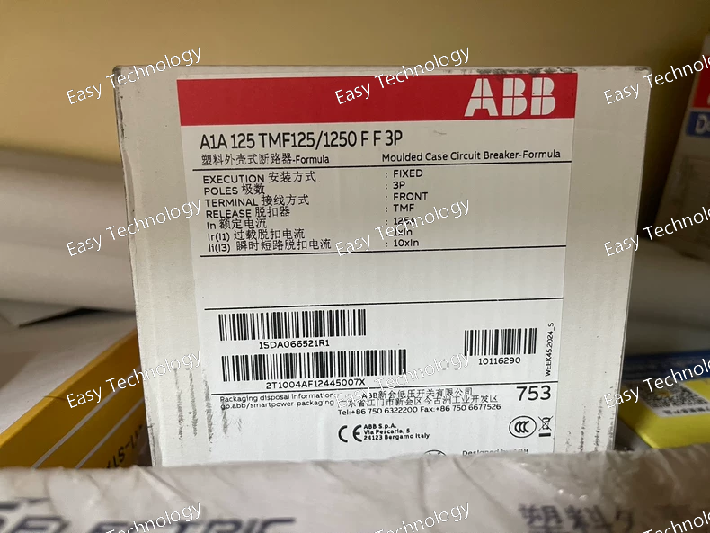
Key Features Circuit Breaker Type: 3‑pole fixed molded case circuit breaker (MCCB). Trip Unit: Thermomagnetic (TMF) release — offers overload and short‑circuit protection in one unit. Terminal Type: Front terminals for easy connection in panel or distribution board installations. Compact Design: Space‑efficient profile suitable for modular panel layouts. Durability: Engineered for frequent switching and fault interruption cycles. Electrical Ratings Rated Current (In): 125 A — continuous load capacity. Rated Operational Voltage: Suitable for AC systems up to ~550 V AC and DC up to ~250 V DC. Rated Insulation Voltage (Ui): ~690 V. Impulse Withstand Voltage (Uimp): ~6 kV. Rated Ultimate Short‑Circuit Breaking Capacity (Icu): High breaking capacity appropriate for industrial power distribution levels. Service Short‑Circuit Breaking Capacity (Ics): Substantial portion of Icu to provide dependable service interruption performance. Operating Frequency: Designed for standard industrial power frequencies (50/60 Hz). Tripping Mechanism: Thermal element: Protects against sustained overloads. Magnetic element: Instantaneous protection against high short‑circuit currents. Mechanical & Environmental Number of Poles: 3 poles — simultaneous protection of all three phases in three‑phase systems. Electrical Durability: Rated for multiple make/break cycles throughout service life. Mechanical Durability: Built for a high number of mechanical operations. Operating Temperature Range: Suitable for typical industrial ambient conditions. Enclosure Protection: Intended for installation inside electrical panels or enclosed distribution boards with appropriate protection ratings. Physical & Installation Mounting: Panel or enclosure installation, front‑accessible connections. Terminals: Front‑tie connections for convenient wiring. Dimensions: Compact footprint that fits standard industrial panel layouts. Weight: Designed to balance robustness with manageable physical size. Typical Applications Branch‑circuit protection in industrial and commercial power distribution. Protection of motor feeders, transformers, and distribution circuits in machinery and plant installations. Main or sub‑panel protection where a reliable breaker with thermomagnetic trip characteristics is required. Load isolation and system safety in electrical switchboards and control cabinets.
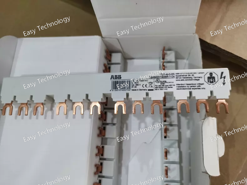
Key Features 3‑phase busbar for four positions, enabling parallel connection of up to four manual motor protectors. Designed for compact motor protection installations and modular panels. Space‑efficient, straight‑bar design for clean connections. Common feed distribution for L1, L2, and L3 phases. Electrical Ratings Rated Operational Current: 65 A — supports a continuous current up to this value for each phase. Rated Operational Voltage: Suitable for low‑voltage AC applications up to 690 V and also compatible with lower DC voltages (e.g., 250 V). Short‑Circuit Capability: High short‑circuit withstand capability for robust performance in industrial systems. Rated Impulse Withstand Voltage: Designed to tolerate voltage transients up to several kilovolts in control and distribution circuits. Mechanical & Environmental Number of Poles / Phases: 3 poles (L1, L2, L3) for three‑phase systems. Number of Mountable Devices: 4 positions for up to four manual motor protectors. Connection Style: Fork‑type busbar connection for secure mechanical and electrical engagement. Protection Rating: IP20 when installed inside an electrical enclosure — touch protection for terminals. Pollution Degree: Suited for typical industrial environments. Physical & Installation Length: ~176.5 mm — compact footprint for modular wiring lanes. Height: ~32.3 mm Depth: ~13 mm Weight: Lightweight bar section for easy handling and installation. Mounting: Designed to be placed between manual motor protectors and to align with their terminals without additional hardware. Typical Applications Parallel feed distribution for MS116 / MS132 manual motor protectors in motor control centers and equipment panels. Wiring simplification in low‑voltage power distribution cabinets. Industrial control panels where multiple protective devices share a common supply. OEM and retrofit applications aiming to reduce wiring time and errors.
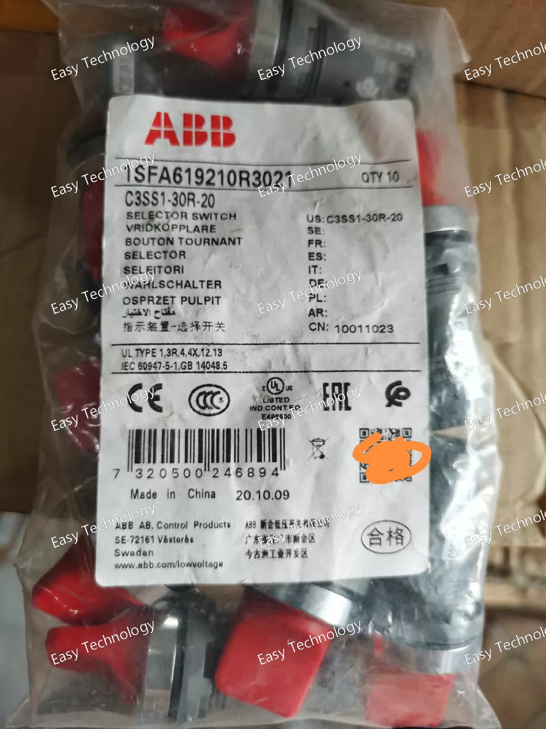
Key Features Selector Type: 3‑position maintained rotary selector switch. Actuator: Short red handle for intuitive manual operation. Design: Non‑illuminated selector with a chrome metal bezel and robust construction. Function: Maintained — the switch stays in the selected position until changed by the operator. Compact Range: Space‑efficient design for standard control panels. Electrical Ratings Contact Configuration: 2 Normally Open (2 NO) auxiliary contacts for control circuit switching. Rated Operational Voltage: Up to 300 V AC/DC in typical control system environments. Rated Operational Current: Suitable for AC‑15 control duties (e.g., around 1 A at 220–240 V AC). Suitable for DC‑13 control duties at lower DC voltages. Rated Insulation Voltage: Designed for standard low‑voltage control circuits. Rated Impulse Withstand Voltage: Suitable withstand for transient events in normal use. Mechanical & Environmental Positions: Three fixed maintained positions (A, B, C). Mechanical Durability: Designed for a high number of operations in industrial settings. Operating Temperature Range: Suitable for typical industrial ambient conditions. Storage Temperature Range: Broader range for shipping and storage conditions. Protection: Good ingress protection at the front when correctly mounted; terminals protected when installed inside an enclosure. Physical & Installation Panel Cut‑out: Fits a standard 22 mm pilot device cut‑out. Bezel Material: Chrome metal for durability and panel aesthetics. Housing: Plastic body suitable for industrial environments. Terminals: Screw‑type terminals for secure wiring. Typical Applications Mode selection (e.g., Off/Auto/Manual) in industrial control panels. Operator interfaces for machinery and process control equipment. Control logic inputs for PLCs, relays, and contactor systems. Multi‑position manual selection for automation systems.
 TEL: Grace +86 13600179521
  Mail: info@hongkongeasy.com jilineasyyi@outlook.com
 Q Q:615739355
 ADDRESS:Unit 12, 20th Floor, Good View Commercial Centre, 2-16 Garden Street, Mong Kok, Hong Kong
 whats app


