
Industrial Controller
All product are in stock,guaranteed delivery within 3-7 days.


PRODUCT
PICTURE
BRAND
DESCRIBE
STOCK
DOWNLOAD
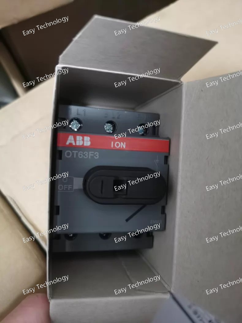
Parameter Specification Product Series OT / OST Series (Switch-Disconnector-Fuse Combination Unit) Device Type 3-Pole Fusible Load Break Switch / Switch-Disconnector Rated Operational Current (Ie) 63 A (This is the current rating of the switch mechanism itself) Rated Fuse Current Up to 63 A (Must be fitted with fuses of equal or lower rating, e.g., 50A, 63A gG/gL or aM types) Number of Poles 3 Poles (3P) Rated Operational Voltage (Ue) 400 V AC (3-phase) / 690 V AC Utilization Category AC-22B or AC-23B (For switching mixed or motor loads with fuse protection) Rated Making & Breaking Capacity Depends on fuse type. With correct fuses, can achieve very high short-circuit breaking capacity (e.g., 100kA+ at 400V AC, determined by fuse). Switch Mechanical Endurance ≥ 10,000 operations Control Method Manual rotary operation via a detachable handle. Handle can typically be padlocked in the OFF position. Mounting 35 mm symmetrical DIN rail (EN 60715) Width 54 mm (3 standard modules, each 18mm) Terminal Type Screw clamp terminals for line/load and fuse connection. Connection Capacity Typically up to 35 mm² (for 63A model) Protection Degree IP00 (must be installed inside an enclosure). Front operation area with handle mounted achieves higher IP rating. Standards Compliance IEC/EN 60947-1, IEC/EN 60947-3 (Switch-disconnector part) Ambient Temperature (Operation) -25°C to +60°C
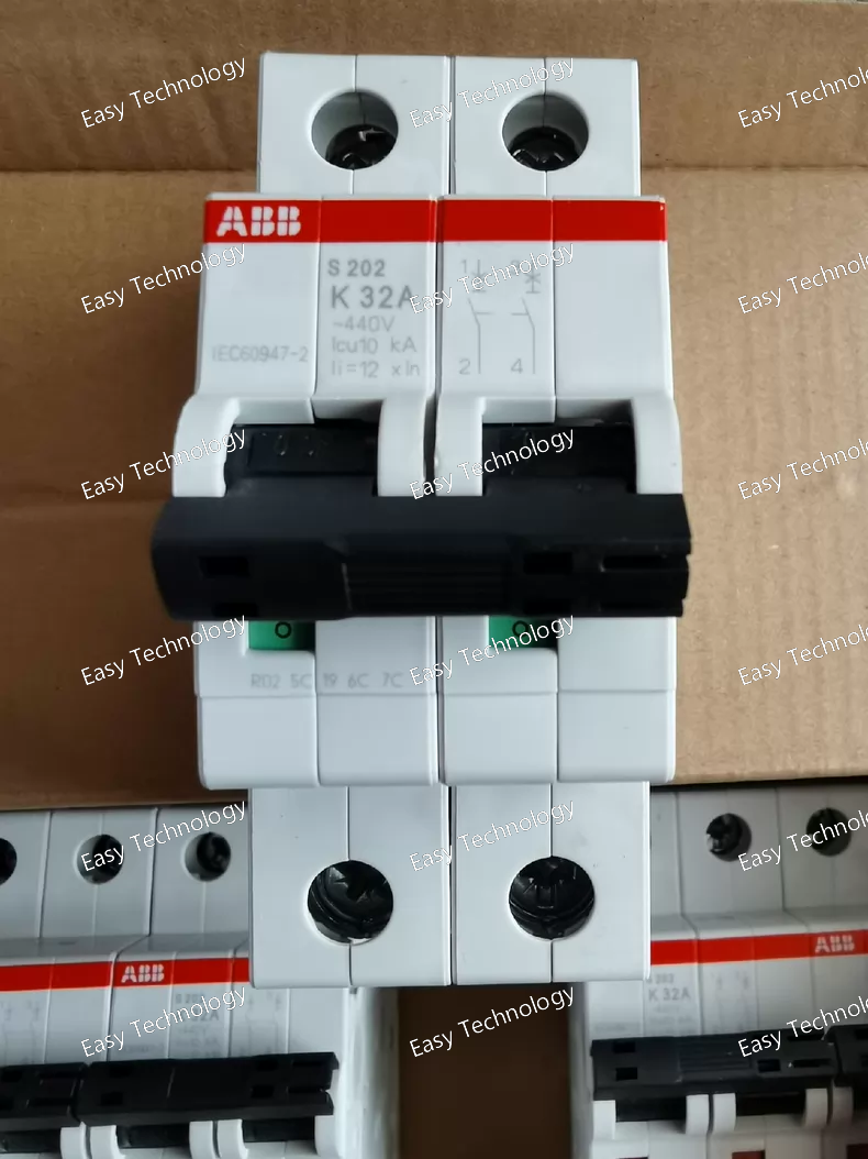
Parameter Specification Product Line / Series System Pro M compact S200 (S200 Series) Device Type Miniature Circuit Breaker (MCB) with K Curve Poles 2P (Two Poles) Rated Current (Iₙ) 32 A Rated Voltage (Uₙ) 230/400 V AC Rated Frequency 50/60 Hz Breaking Capacity (Icn) 6 kA (at 230/400V AC). Note: Higher capacity versions (e.g., S200M series with 10kA) may also offer K curve. Tripping Characteristic K Curve (Instantaneous magnetic trip operates between approximately 8 to 14 times Iₙ, i.e., between ~256A and ~448A). This provides higher intrush withstand compared to C curve (5-10x In) but faster response than D curve (10-20x In) for short-circuits. Mechanical Endurance ≥ 20,000 operations Electrical Endurance ≥ 10,000 operations (at Iₙ) Mounting 35 mm symmetrical DIN rail (EN 60715) Width 36 mm (2 standard modules, each 18mm) Terminal Torque 2.5 - 3.0 Nm (for rated cross-section conductors) Connection Capacity Rigid Cable: 1x 35 mm² / 2x 25 mm² Flexible Cable: 1x 25 mm² (with ferrule) / 1x 35 mm² (with ferrule) Standards Compliance IEC/EN 60898-1, IEC/EN 60947-2 Ambient Temperature (Operation) -25°C to +55°C
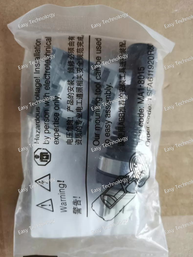
Parameter Specification Device Type Rotary Load Break Switch / Disconnector Product Series MJ / MJS Series Rated Operational Current (Ie) 60 A (at specified utilization category) Number of Poles 2 Poles (2P) Rated Insulation Voltage (Ui) 690 V Rated Operational Voltage (Ue) 400 V AC / 500 V AC Utilization Category AC-22A (Switching of mixed resistive and inductive loads). AC-23A (Switching of motor loads or other highly inductive loads). Rated Making & Breaking Capacity Typically ≥ 10 x Ie (e.g., 600 A) for AC-23A at 400V. Short-Time Withstand Current (Icw) Typically 10 kA for 1 second (This is a key safety parameter, ensuring it can withstand fault currents without damage). Mechanical Durability ≥ 10,000 operations Electrical Durability ≥ 5,000 operations (at rated current) Control Method Manual rotary operation via a detachable handle. The handle can be padlocked in the OFF position (typically with up to 3 padlocks). Mounting Mounts directly onto a panel or enclosure door via a mounting kit. The switch body is mounted behind the panel. Terminal Type Screw clamp terminals. The "B" variant may include snap-on protective terminal covers. Terminal Connection Capacity Typically up to 35 mm² (for 60A model). Protection Degree Switch body: IP00 (must be installed inside an enclosure). With handle mounted on door: Typically achieves IP54 or higher for the front. Ambient Temperature (Operation) -25°C to +60°C Standards Compliance IEC/EN 60947-1, IEC/EN 60947-3
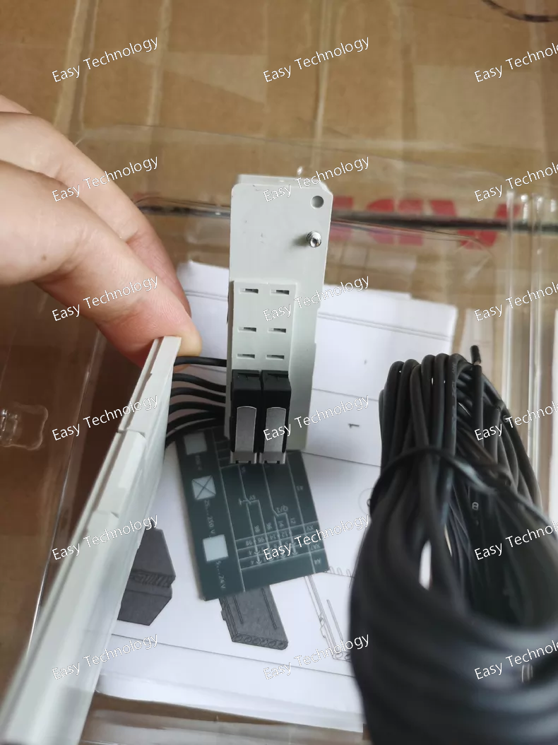
Parameter Specification Product Family Accessory for ABB Emax 2 (E2) Air Circuit Breakers & compatible MCCBs. Device Type Mechanically Operated, Cabled Auxiliary Contact Block Article Number 1SDA054910R1 Contact Configuration 1 NO (Normally Open) + 1 NC (Normally Closed) Form: 1 Changeover (SPDT) contact (logically derived from 1Q1SY). Contact Rating (Utilization Category) AC-15: 250V, 2.5 A DC-13: 250V, 0.2 A (Typical values for auxiliary contacts. Confirm from official sheet) Rated Operational Voltage (Ue) 250 V AC / 250 V DC Rated Thermal Current (Ith) 10 A Mechanical Life ≥ 10,000 operations (aligned with breaker mechanical endurance) Electrical Life ≥ 100,000 operations (at rated resistive load) Output Connection Pre-fitted flexible cables (Approx. 500mm length, specific color code). Cables are terminated with bare ends or pin terminals for connection to customer's terminal block. Cable Specification Typically multi-core, fine-strand control cable with insulation suitable for panel wiring. Mounting / Compatibility Direct mechanical mounting onto designated point on the Emax 2 breaker operating mechanism. The T4-6 code specifies exact compatibility (e.g., for breakers with rotary handle mechanisms of certain frame sizes). Operation Actuated directly by the breaker's moving parts. Contacts change state in sync with the main contacts. Standards Compliance IEC/EN 60947-5-1 (Auxiliary devices for circuit-breakers) Ambient Temperature -25°C to +70°C (Operation)
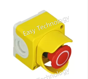
Parameter Specification Product Family / System ABB Freelance Distributed Control System (DCS) Module Type Digital Input Module Article Number CEPY1-2001 Number of Channels 16 (Sixteen independent input channels) Input Type Sinking or Sourcing (typically configurable, for connection to PNP or NPN sensors). Designed for 24V DC field devices. Nominal Input Voltage 24 V DC Permissible Input Voltage Range Typically 19.2 V DC to 30 V DC Input Current per Channel Typically 3-5 mA (at 24V DC) Logic "1" Signal Level ≥ 15 V DC (ON state) Logic "0" Signal Level ≤ 5 V DC (OFF state) Isolation Channel-to-Channel Isolation: Typically not isolated. Group Isolation: Channels are isolated from the system bus/power supply (e.g., 500 V AC). Connection Method Via a removable front connector block (e.g., screw terminal or spring-cage type), which connects to the module's rear connector. Common wiring for field devices. Diagnostics Module status indication via LEDs (e.g., POWER, READY, CHANNEL STATUS). May support wire-break detection. Mounting DIN rail mounting (35 mm) within a Freelance 800F I/O station enclosure or panel. Bus Communication Connects to the Freelance Controller (AC 700F/900F) via a local I/O bus (e.g., CI830 or CI840 communication interface module and associated bus). Ambient Temperature Operation: 0°C to +60°C (standard) Storage: -40°C to +85°C Standards Compliance IEC 61131-2, cULus Listed, CE Marked, etc.
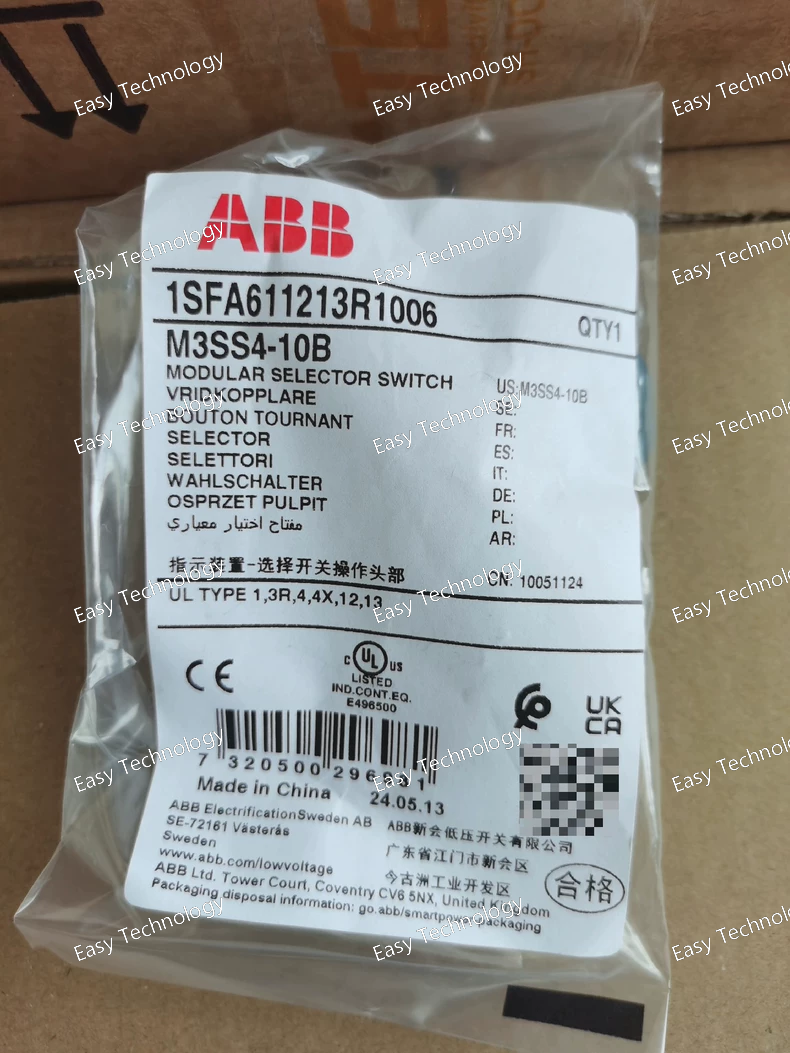
Parameter Specification Product Series M3S Series (Modular Control & Signalling Devices) Device Type Maintained-Contact Pushbutton Selector Switch (Momentary action with mechanical latching) Contact Configuration 1 Changeover Contact (SPDT / Form C) - 1 NO + 1 NC Contact Rating (Resistive Load) Typically: 4 A @ 250 V AC / 2 A @ 250 V DC Minimum Load: 10 mA / 5 V DC Electrical Life ≥ 1 x 10⁶ operations (at rated load) Mechanical Life ≥ 5 x 10⁶ operations Rated Insulation Voltage (Ui) 250 V Degree of Protection Front: IP40 (when mounted) Terminals: IP20 Mounting Snap-on mounting into a standard 22.5mm x 22.5mm mounting hole on a panel (typically 1.5mm thick). Requires a separate mounting frame/surround (e.g., ABB M3S frame). Actuator Type Square, flush or slightly raised pushbutton. The "10B" code often specifies the exact style and color (e.g., black, red, blue, etc.). "B" commonly denotes a specific actuator variant. Terminal Connection Screw clamp terminals Connection Capacity Up to 1.5 mm² (stranded wire with ferrule recommended) Ambient Temperature Operation: -25°C to +70°C Storage: -40°C to +85°C Standards Compliance IEC/EN 60947-5-1, UL 508, CSA C22.2 No. 14
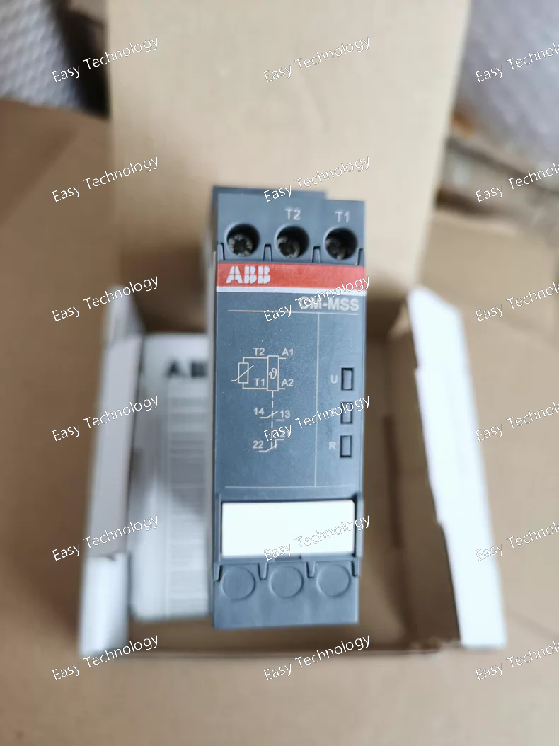
Technical Data Parameter Specification / Typical Value Product Series / System CM-MSS Modular Surge Protection System Device Type Type 2 / Class II Surge Protection Device (SPD) Application Class Class II (Per IEC 61643-11 / EN 61643-11) Rated Voltage (Un) 230 V AC (50/60 Hz) Max. Continuous Operating Voltage (Uc) 275 V AC (This is the maximum RMS voltage it can withstand continuously. Must be verified with the official datasheet). Voltage Protection Level (Up) Typically ≤ 1.5 kV (at In). This is the residual voltage measured across its terminals during a surge, defining its protective capability. Confirm exact value from datasheet.) Nominal Discharge Current (In) 20 kA (8/20 µs wave, per pole). The standard test current it can withstand for 15 surges. Max. Discharge Current (Imax) 40 kA (8/20 µs wave, per pole, single shot). The maximum peak current it can withstand once. System Compatibility TN-S, TN-C-S, TT Response Time < 25 ns Status Indication Visual indicator (e.g., color flag) Auxiliary Contacts Yes, 1 Changeover (SPDT) remote signaling contact (Standard with "S" variant). Thermal Protection Integrated thermal disconnector. Mounting 35 mm symmetrical DIN rail (EN 60715) Module Width 18 mm (1 module, for 1P+N or 1P version) Standards Compliance IEC 61643-11, EN 61643-11 Short-Circuit Withstand Follows the declared Icp value when protected by the recommended upstream fuse/gBreaker (e.g., 63A gL/gG or 50A B-curve MCB).
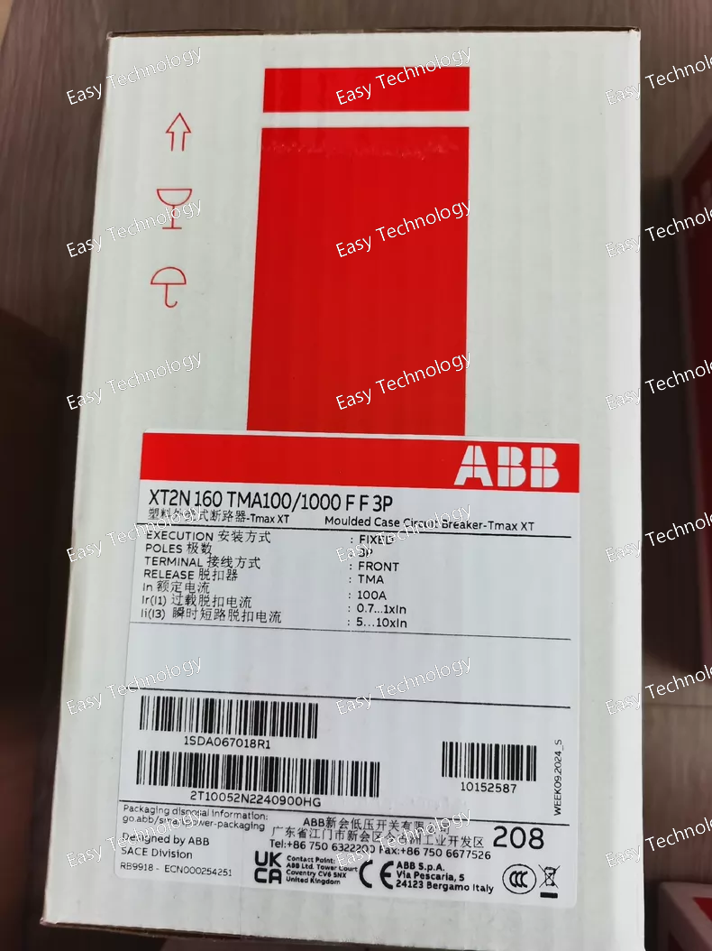
Parameter Specification Product Series / Range XT Series Molded-Case Circuit Breakers Frame Size XT2 Rated Frame Current (Iu) 160 A Rated Ultimate Breaking Capacity (Icu @ 400V AC) N-type: Typically 50 kA (Please confirm with official XT2N data sheet). L/H versions have different ratings. Number of Poles 3 Poles (3P) Trip Unit Type Electronic Trip Unit - TMA (or TMA-LSI). Provides Long-time (L), Short-time (S), Instantaneous (I) protection functions. May include Ground Fault (G). Rated Current Setting (Ir) Set to 100 A (Continuously adjustable within a range, e.g., 0.4 - 1 x In, where In might be the sensor rating. *The notation "100/1000" likely indicates Ir=100A on a scale up to 1000A*). Rated Operational Voltage (Ue) 400 V AC (3-phase) Rated Insulation Voltage (Ui) 800 V AC Connection Type Fixed Version, Front Terminal (FF) Terminal Type Screw-type terminals for front cable connection. Adjustable Protection Settings (Typical for TMA) • Long-Time (L): Ir = 100 A (Set), tr (Time delay) adjustable. • Short-Time (S): Isd (Pickup, multiple of Ir) adjustable, tsd (Time delay) adjustable. • Instantaneous (I): Ii (Pickup, multiple of Ir) adjustable. Standard Compliance IEC/EN 60947-1, IEC/EN 60947-2 Mounting Fixed mounting on panel or inside switchboard cubicle. Control / Operation Manual operating handle. Can be equipped with motor operator (M2C), shunt trip (MX), under-voltage release (MN), and auxiliary contacts (OF, SD) as accessories. Ambient Temperature (Operation) -25°C to +70°C (Storage: -40°C to +85°C)
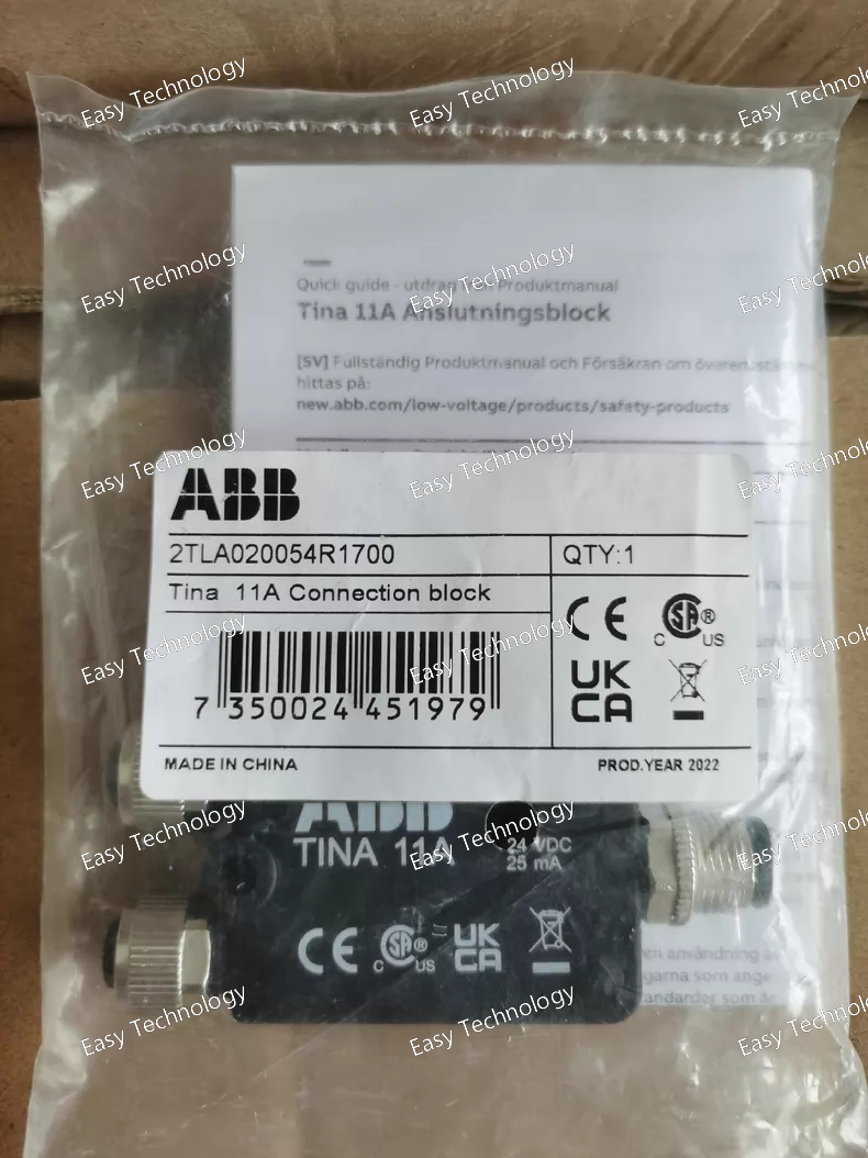
Parameter Specification Product Series TINA (Terra Indicating and Auxiliary) Relay Series Device Type Monostable, Electromechanical Latching Relay (with auxiliary contact) Order Code / Article Number 2TLA20054R1700 Coil Data (Control Circuit) - Coil Voltage (Standard) 24 V DC (Other voltages available, e.g., 12V DC, 24-230V AC/DC. Must be verified for this specific article number). - Coil Power Consumption Typically ~0.9 W (for DC coil) / ~1.3 VA (for AC coil) Contact Data (Main Circuit) - Number & Configuration of Main Contacts 2 Changeover (CO) / Form C contacts. (1 NO + 1 NC per contact pair). - Rated Operational Current (Ie) 10 A @ 250 V AC - Rated Operational Voltage (Ue) Up to 400 V AC / 250 V DC - Rated Thermal Current (Ith) 16 A - Switching Capacity (Resistive Load) AC-1: Up to 4000 VA DC-1: Up to 60 W Auxiliary Contact (Indicator) - Configuration 1 Normally Open (NO) / Form A contact. - Rated Operational Current (Ie) Typically 6 A @ 250 V AC. Mechanical & Electrical Life - Mechanical Endurance ≥ 10 x 10⁶ operations - Electrical Endurance (at rated load) ≥ 0.2 x 10⁶ operations Switching Time Typically ~10 ms Mounting 35 mm symmetrical DIN rail (EN 60715) via optional mounting base (e.g., ABB TINA Base). Can also be panel-mounted. Terminal Type Screw clamp terminals. Connection Capacity Up to 2.5 mm² (flexible with ferrule) / 4 mm² (rigid) Ambient Temperature (Operation) -40°C to +70°C Protection Degree IP40 (with base), IP20 (terminals) Standards Compliance IEC/EN 61810-1, IEC/EN 60947-5-1
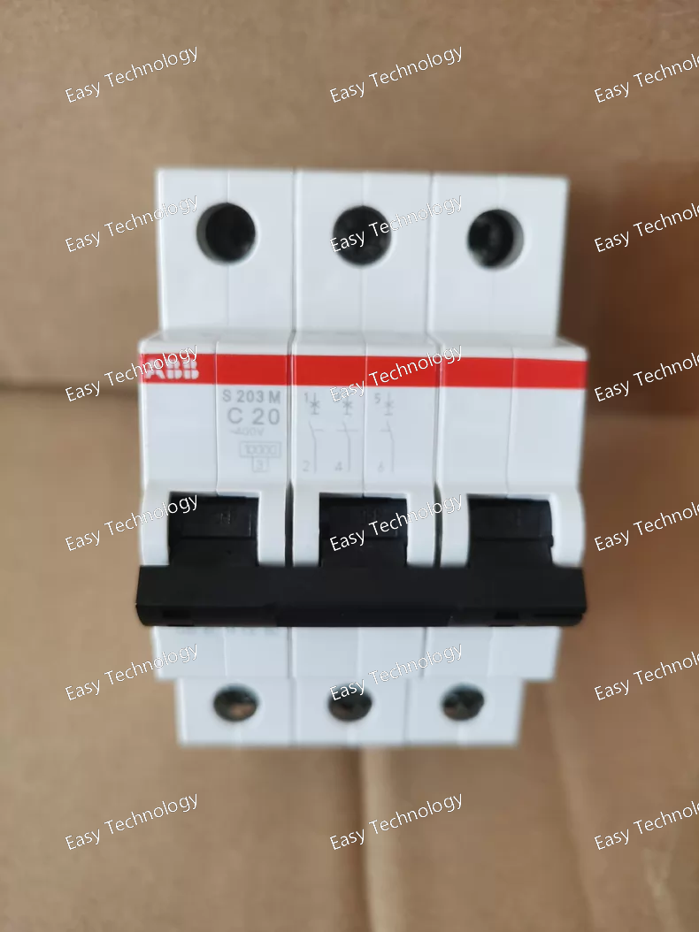
Parameter Specification Product Line / Series System Pro M compact S200 (S200M Series - Moulded Case) Device Type Miniature Circuit Breaker (MCB) Poles 3P (Three Poles) Rated Current (Iₙ) 20 A (per pole) Rated Voltage (Uₙ) 400 V AC (3-phase) Rated Frequency 50/60 Hz Breaking Capacity (Icn) 10 kA (at 400V AC) - The key differentiator of the S200M series. Tripping Characteristic C Curve (Instantaneous magnetic trip operates between 5 to 10 times Iₙ, i.e., between 100A and 200A per pole). Ideal for circuits with moderate inrush currents, such as small three-phase motors, transformers, and general three-phase loads. Mechanical Endurance ≥ 20,000 operations Electrical Endurance ≥ 10,000 operations (at Iₙ) Mounting 35 mm symmetrical DIN rail (EN 60715) Width 54 mm (3 standard modules, each 18mm) Terminal Torque 2.0 - 2.5 Nm (for rated cross-section conductors) Connection Capacity Rigid Cable: 1x 25 mm² / 2x 16 mm² (per pole) Flexible Cable: 1x 16 mm² (with ferrule) / 1x 25 mm² (with ferrule) (per pole) Standards Compliance IEC/EN 60898-1, IEC/EN 60947-2 Ambient Temperature (Operation) -25°C to +55°C Storage Temperature -40°C to +70°C Protection Degree (Terminals) IP20
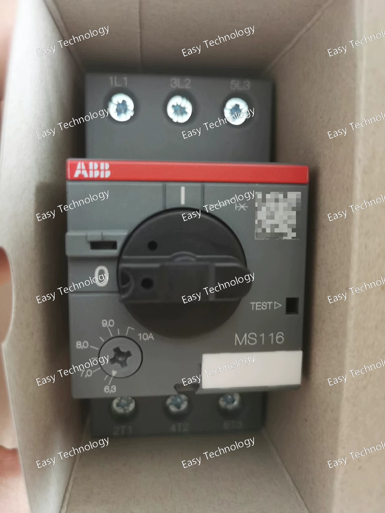
Parameter Specification Product Line / Series System M (M200 S-series) - MSxxx compact series Device Type Miniature Circuit Breaker (MCB) - 1P+N (Single Pole + Neutral) Protected Poles 1 (Phase/Live conductor only) Switched Poles 2 (Both Phase and Neutral are mechanically switched together) Rated Current (Iₙ) 10 A (Applies to the protected phase pole) Rated Voltage (Uₙ) 230/400 V AC Rated Frequency 50/60 Hz Breaking Capacity (Icn) 10 kA (at 230/400V AC) Tripping Characteristic C Curve (Instantaneous trip between 5x and 10x Iₙ, i.e., 50A to 100A). Suitable for general-purpose circuits with moderate inrush currents. Mechanical Endurance ≥ 20,000 operations Electrical Endurance ≥ 10,000 operations (at Iₙ) Mounting 35 mm symmetrical DIN rail (EN 60715) Width 18 mm (1 standard module – this is its key advantage) Terminal Torque 1.5 Nm (for rated cross-section conductors) Connection Capacity Typically up to 16 mm² (Confirm with official datasheet for the 10A model) Standards Compliance IEC/EN 60898-1 Ambient Temperature (Operation) -25°C to +55°C
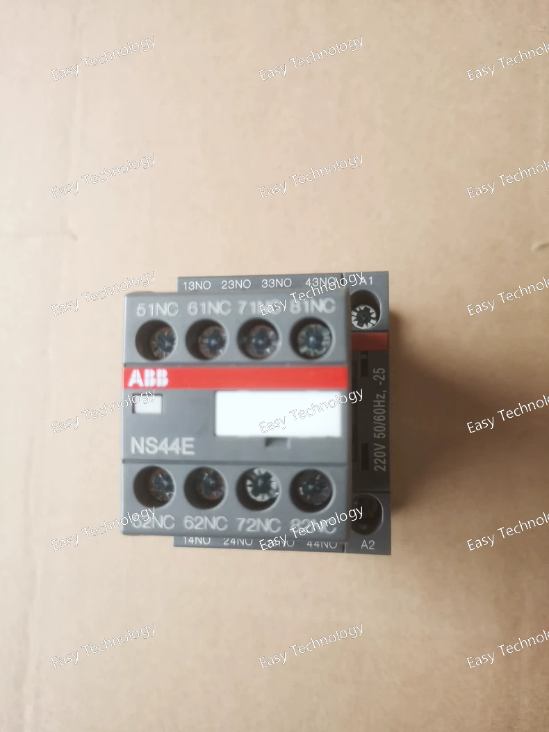
Parameter Specification Product Line / Series System E (S200 S-series) Device Type Miniature Circuit Breaker (MCB) Poles 4P (Four Poles – L1, L2, L3, N - all protected) Rated Current (Iₙ) 25 A (per pole) Rated Voltage (Uₙ) 400 V AC (3P+N) Rated Frequency 50/60 Hz Breaking Capacity (Icn) 6 kA (at 230/400V AC) Tripping Characteristic C Curve (Instantaneous trip between 5x and 10x Iₙ). Suitable for applications with moderate inrush currents typical in three-phase installations. Mechanical Endurance ≥ 20,000 operations Electrical Endurance ≥ 10,000 operations (at Iₙ) Mounting 35 mm symmetrical DIN rail (EN 60715) Width 72 mm (4 standard modules, each 18mm) Terminal Torque 2.0 - 2.5 Nm (for rated cross-section conductors) Connection Capacity Rigid Cable: 1x 25 mm² / 2x 16 mm² (per pole) Flexible Cable: 1x 16 mm² (with ferrule) / 1x 25 mm² (with ferrule) (per pole) Standards Compliance IEC/EN 60898-1, IEC/EN 60947-2 Ambient Temperature (Operation) -25°C to +55°C Storage Temperature -40°C to +70°C
 TEL: Grace +86 13600179521
  Mail: info@hongkongeasy.com jilineasyyi@outlook.com
 Q Q:615739355
 ADDRESS:Unit 12, 20th Floor, Good View Commercial Centre, 2-16 Garden Street, Mong Kok, Hong Kong
 whats app


