
Industrial Controller
All product are in stock,guaranteed delivery within 3-7 days.


PRODUCT
PICTURE
BRAND
DESCRIBE
STOCK
DOWNLOAD
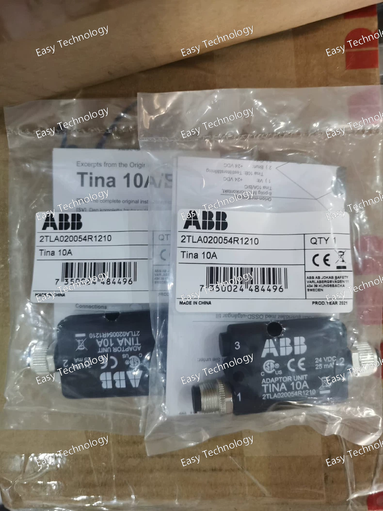
Technical Parameters General Product Type: Safety interface / DYNlink adapter Model / Ordering Code: 2TLA020054R1210 (TINA 10A v2) Function: Adapts OSSD safety outputs to DYNlink safety loop signals Application Category: Machine safety, safety sensor integration Protection Rating: IP67 (splash/dust protection suitable for industrial environments) Housing Material: Industrial‑grade rugged plastic Approx. Weight: ~0.03 kg Approx. Dimensions: ~77 mm (length) × ~36 mm (width) × ~14 mm (height) Connectors / Interface DYNlink Loop Connector: M12‑5 male OSSD Device Connector: M12‑8 female Connector Standard: Circular M12 industrial connectors Electrical / Signal Supply Voltage: Typical 24 V DC for adaptor operation (via safety system supply) Total Current Consumption: Nominal ~25 mA; Max ~35 mA DYNlink Input Signal Voltage Range: ~8 – 15 V RMS (signal link) DYNlink Output Signal Voltage Range: ~8 – 15 V RMS OSSD Input Current per Channel: ~10 mA typical Output Contact / Information Output: Signal high ~22 V DC; low < 2 V DC; max 10 mA Performance Signal Delay: < 120 µs between input and output DYNlink signals Duty: Designed for continuous safety system integration with quick response Signal Compatibility: Interfaces optical safety components’ OSSD outputs with DYNlink safety loops Environmental Operating Temperature: ~‑10 °C to +55 °C Storage Temperature: ~‑10 °C to +55 °C Humidity Range: 35 % to 85 % (no icing or condensation) Protection Level: IP67 rated enclosure for dust/water resistance Safety & Standards Intended for integration in machine safety control circuits Provides secure adaptation of safety sensor outputs for use with DYNlink‑based safety controllers Robust industrial connectors and rated protections for reliable field wiring Applications Machine safety systems requiring connection of optical safety sensors to safety controllers Interfacing OSSD outputs (e.g., from light curtains, safety scanners, electro‑sensitive protective equipment) to DYNlink networks Integration with PLC safety modules and safety bus loops in automated equipment Safety signal conditioning in manufacturing and process automation panels
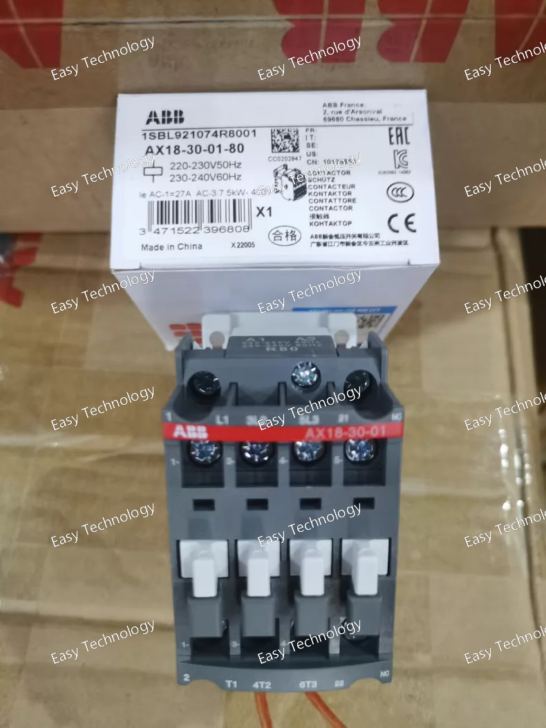
Technical Parameters General Product Type: AC magnetic contactor Model: AX18‑30‑01‑80 Series: AX family of contactors Poles: 3 main power poles Auxiliary Contacts: 0 Normally Open (NO), 1 Normally Closed (NC) Electrical Ratings Rated Operational Current (AC‑3): ~18 A (typical for this size) Rated Operational Current (AC‑1): Higher capacity for non‑motor loads Rated Insulation Voltage (Ui): ~690 V AC Rated Operational Voltage: Up to ~690 V AC (main circuit) Control (Coil) Voltage: Variant ‑80 typically indicates coil rated for 220–230 V AC at 50/60 Hz Other coil voltages may be available in the same series (e.g., 24 V, 110 V, 380–415 V AC) Control / Coil Coil Type: AC operated electromagnetic Coil Frequency: Compatible with 50 Hz and 60 Hz supplies Coil Operating Range: Designed to operate reliably at the rated coil voltage with standard tolerances Performance Motor Rated Operational Power (AC‑3): Suitable for motors in the range typical for ~18 A contactor frame (e.g., ~4 kW at 400 V AC) Switching Capacity: Appropriate for general AC loads and motor circuits Electrical Endurance: Designed for frequent switching operations Mechanical Endurance: High life expectancy under normal use Mechanical & Installation Mounting: DIN‑rail or screw panel mounting Terminal Type: Screw clamp terminals for main and auxiliary circuits Contact Material: Industrial‑grade alloy for reliable switching Compact Construction: Saves panel space Environmental Operating Ambient Temperature: Standard industrial range (e.g., −25 °C to +70 °C) Storage Temperature: Typical extended ambient range Pollution Degree: Suitable for industrial environments Standards & Compliance Designed to meet common low‑voltage control and switching equipment standards (IEC/EN 60947 series) Applications Control of three‑phase motors in starters and automation systems General AC load switching in control panels Industrial control and power distribution circuits Integration with overload relays and control logic assemblies
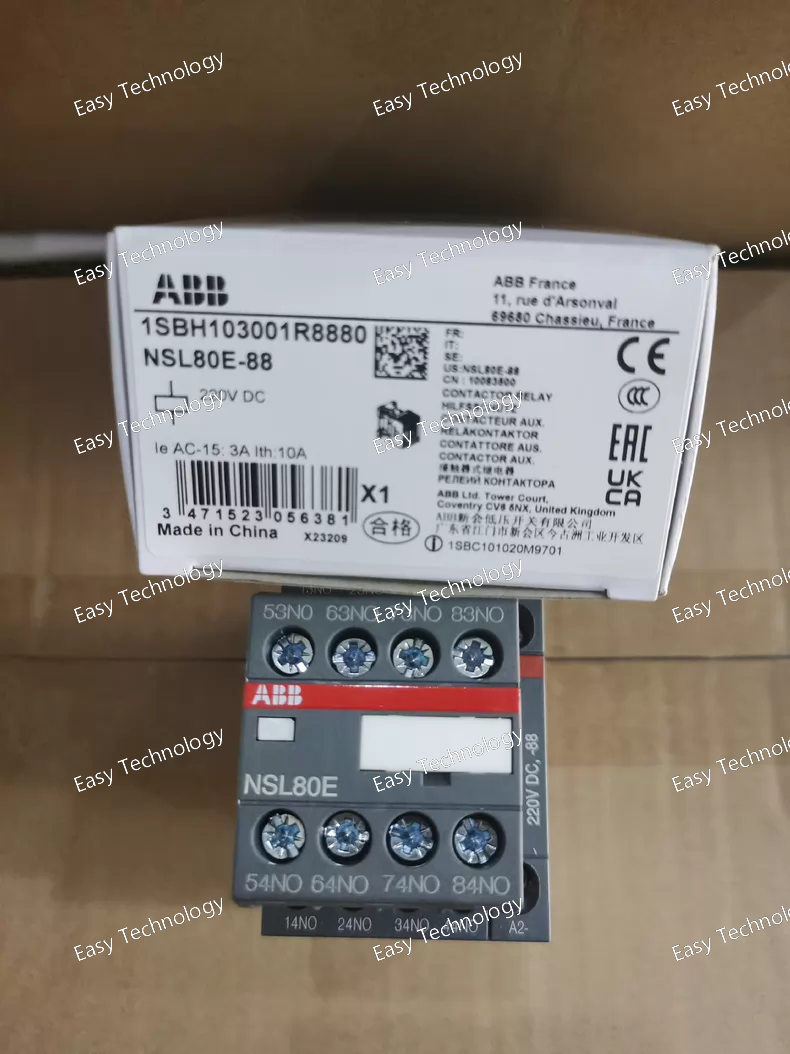
Technical Parameters General Product Type: Contactor relay / control relay Model Family: NSL series (NSL80E) Specific Variant: NSL80E‑88 (DC coil version typically for 220 V DC) Contact Arrangement: 8 × Normally Open (8NO) contacts Number of Poles: 8 poles (control contacts) Mounting: Panel or DIN rail with adapter (depending on panel design) Control / Coil Control Coil Type: DC coil (e.g., 220 V DC) Control Circuit Voltage: Matches the coil variant (e.g., 220 V DC input) Coil Consumption: Industrial relay type coil (designed for continuous energization) Electrical Ratings Rated Operational Voltage (Auxiliary circuits): Suitable for control and signal levels (up to typical industrial control voltages, e.g., 250 V) Rated Insulation Voltage: High insulation for auxiliary circuits Conventional Free‑air Thermal Current (Ith): ~16 A for auxiliary contacts Rated Operational Current AC‑15: Typical rated control load as per industrial standards (e.g., 4 A at 220–240 V AC, varies by contact standard) Operating Frequency: DC coil, contact switching handles AC/DC loads compatible with category ratings Switching Duty: Suitable for frequent control switching use Contact & Performance Contact Configuration: 8 independent NO contacts Contact Material: Industrial silver alloy Mechanical Durability: Designed for millions of operations under control conditions Electrical Durability: Rated for frequent switching of auxiliary circuits Mechanical & Terminals Terminal Type: Screw terminals Connection Capacity: Typical industrial panel wiring sizes Housing: Compact relay package with standard width and depth for NSL series devices Environmental Operating Ambient Temperature: Standard industrial ambient range (e.g., −40 °C to +55 °C near contactor for continuous operation when energized at 0.85…1.1×Uc) Storage Temperature: Extended ambient range (e.g., −60 °C to +80 °C) Pollution Degree: Industrial control environments Altitude Rating: Up to typical industrial elevations (~3000 m) without derating Standards & Compliance Meets international industrial control relay standards for insulation, mechanical endurance, and contact duty. Applications Switching of control and auxiliary circuits Interface to PLC or automation systems Panel logic control in industrial equipment Multiple contact outputs for status signaling Control panel interlock and sequencing logic
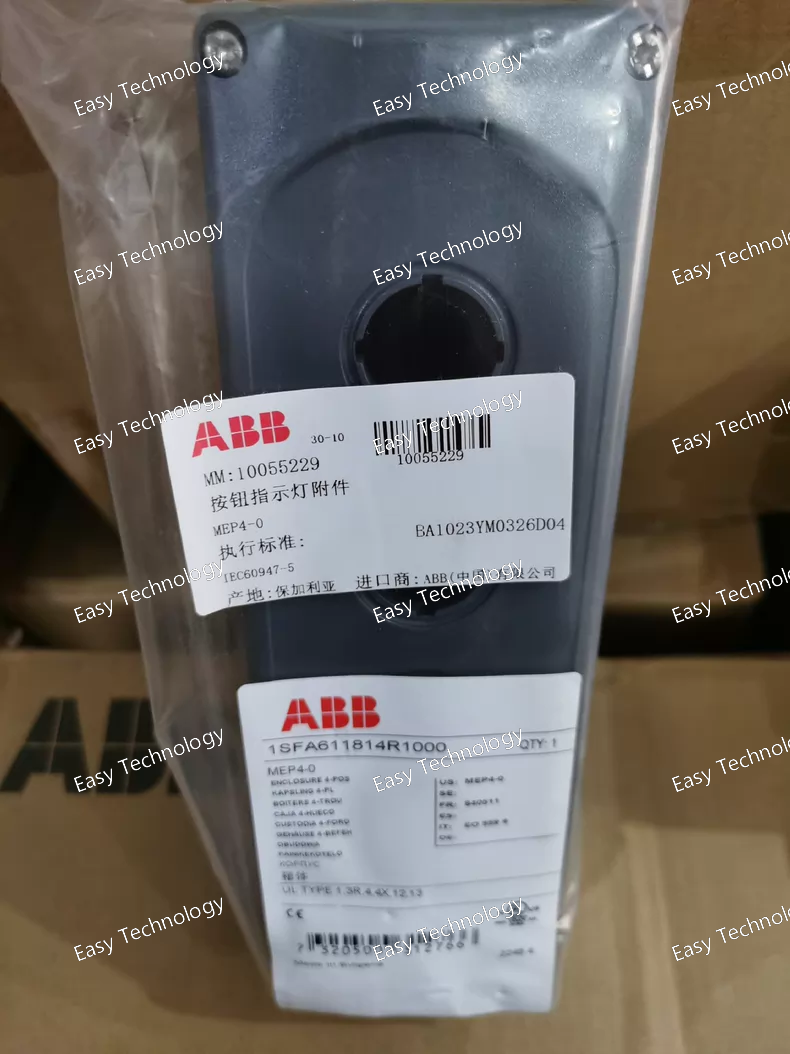
Technical Parameters General Product Type: Pilot device enclosure / control station housing Model: MEP4‑0 Seats / Positions: 4 × 22 mm operator holes Series: Modular pilot device enclosures Mechanical & Construction Housing Material: Heavy-duty polycarbonate plastic Color: Dark gray (cover) / light gray (body) Mounting: Panel mount; face designed for 22 mm operator cut-outs Included Hardware: Stainless steel mounting screws Dimensions & Weight Width: Approx. 221 mm Height: Approx. 61 mm Depth: Approx. 75 mm Weight: Approx. 0.309 kg Operator Cut-out Size: 22 mm diameter per hole Protection & Environmental Ingress Protection: Front IP66 rated for dust/water resistance Operating Temperature Range: –25 °C to +70 °C Storage Temperature: –40 °C to +85 °C Pollution Degree: Suitable for industrial environments Compatibility & Accessories Compatible Operators: Pushbuttons, selector switches, indicator lights, joysticks, and other 22 mm modular ABB pilot devices Contact Blocks: Snap-on or rear mount auxiliary contact blocks and lamp blocks (ordered separately) Cable Entry: Knockout options for wiring feed-through Applications Industrial control stations and operator panels Machine/equipment interface modules Automation system input assemblies Local control stations in manufacturing and power distribution cabinets OEM electrical enclosures and custom control blocks
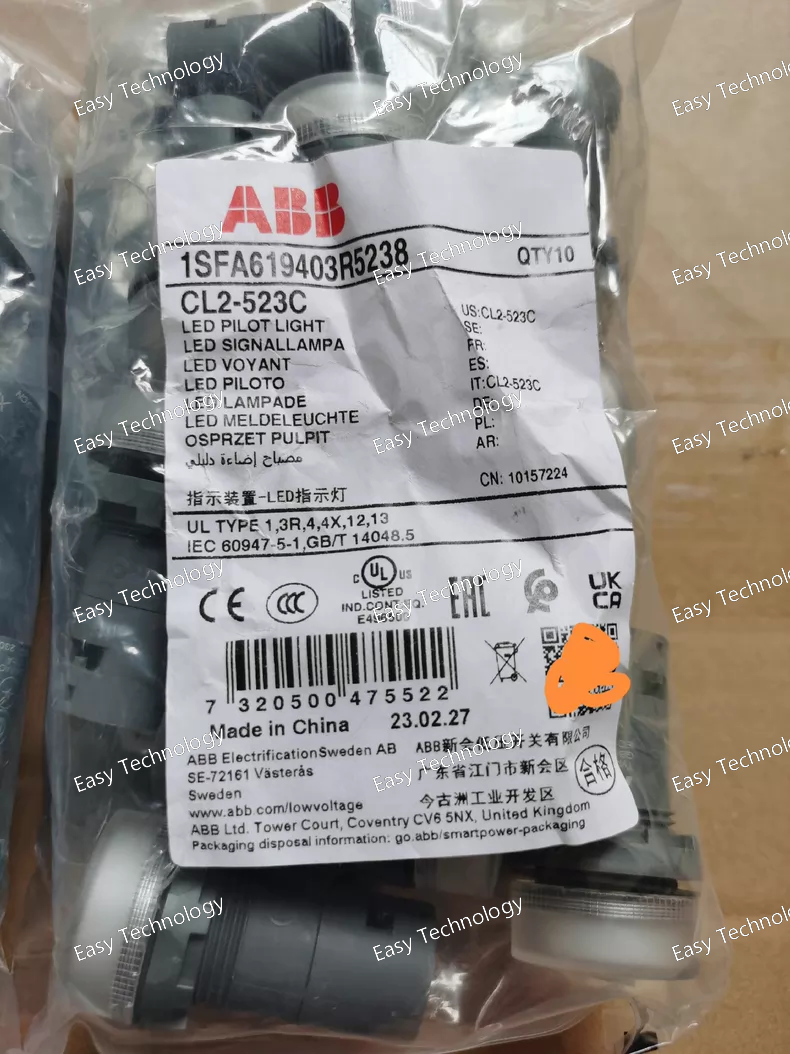
Technical Parameters General Product Type: Illuminated pilot light Model: CL2‑523C Series: CL2 compact pilot devices Lens Color: Clear / transparent Indicator Type: LED illumination Panel Mounting Size: 30 mm nominal cut‑out Electrical Rated Operational Voltage: 230 V AC Rated Frequency: 50 Hz / 60 Hz Current Consumption: ~17 mA Light Source: Integrated LED (no replaceable bulb) Base Type: BA9s‑style mount (LED lamp integrated) Rated Insulation Voltage: Suitable for low‑voltage control circuits Mechanical & Connection Terminal Type: Screw clamp terminals Connecting Capacity: Flexible with ferrule: 0.75 … 2.5 mm² Solid: 0.75 … 2.5 mm² Wire Stripping Length: ~8 mm Tightening Torque: ~0.9 N·m Dimensions (approx): Width: ~30 mm Depth: ~52 mm Net Weight: ~0.018 kg Environmental & Protection Operating Temperature Range: –25 °C to +70 °C Storage Temperature Range: –40 °C to +85 °C Ingress Protection: Front: IP66 / IP67 / IP69K (high dust & water resistance) Terminals: IP20 NEMA / Enclosure Ratings: NEMA 1 / 3R / 4 / 4X / 12 / 13 (when correctly installed in a panel) Pollution Degree: Industrial environments Applications Visual status indication in control panels and switchboards Fault or power‑on indication for machines and equipment OEM electrical panels and automation systems Status signaling in manufacturing and process controls
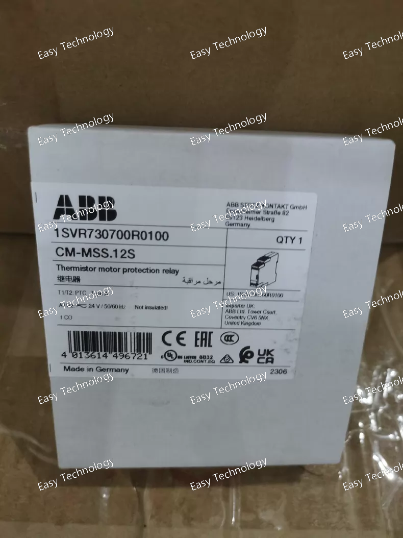
Technical Parameters General Product Type: Current monitoring relay (single‑phase) Model: CM‑SRS.12S Mounting: DIN rail (IEC 60715) Terminal Type: Screw connection terminals Output Contact: 1 × changeover (SPDT) contact Contact Rating: Suitable for control and signal loads (e.g., up to ~250 V, typical industrial relay ratings) Monitoring & Function Monitored Current Type: AC and DC single‑phase Detection Function: Over‑ and under‑current detection based on set thresholds Output Contact Action: Changes state when monitored current exceeds or falls below the configured threshold Adjustability: Threshold and hysteresis adjustable for precise current supervision Indication: Relay output state indicates monitoring status Coil / Supply Control Supply Voltage: Typically supplied in variants such as 24 – 240 V AC/DC depending on version Voltage Type: Compatible with AC/DC supply types (model dependent) Electrical Ratings Output Contact Capacity: Suitable for switching control circuits (e.g., up to ~4 A at 250 V AC) Relay Contact Configuration: SPDT (Single Pole Double Throw) Mechanical & Physical Width: ~22.5 mm (1 module wide) Height: ~85.6 mm Depth: ~103.7 mm Housing: DIN‑rail industrial enclosure Mounting Rail: 35 mm DIN rail Performance & Response Response Time: Fast response to current changes (typically < 100 ms) Hysteresis: Adjustable to prevent chattering around threshold point Accuracy: Suitable for precise current monitoring in control systems Environmental Operating Ambient Temperature: Standard industrial ambient range Pollution Degree: Industrial environments Protection Rating: IP20 at terminal level (front/protection depends on panel installation) Applications Current monitoring in industrial control panels Motor supervision and protection circuits Alarm signalling for current thresholds Automation control logic (PLC/relay inputs) Detection of undercurrent / overcurrent conditions
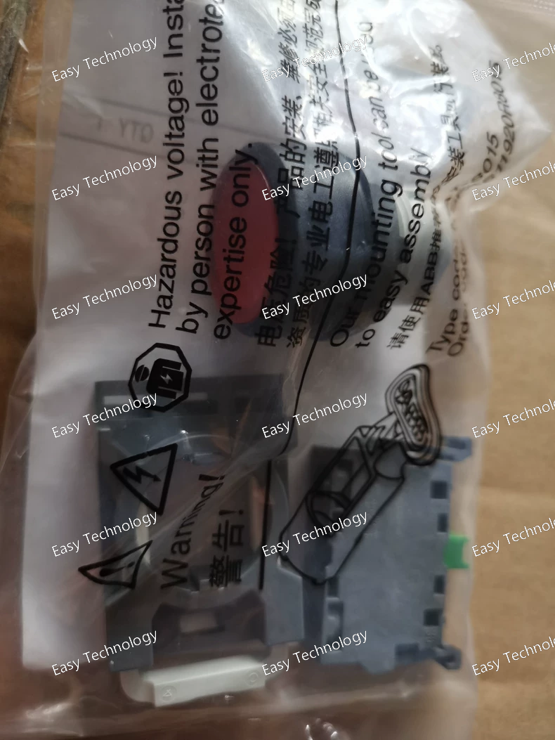
Technical Parameters General Product Type: Manual motor protector (MMP) Model: MP2‑41R‑10 Operator Style: Rotary selector (ON/OFF/RESET) Number of Poles: 3‑pole (three‑phase) Trip Elements: Thermal overload + magnetic (instant trip) Electrical Ratings Rated Operational Voltage (Ue): Up to 690 V AC Rated Insulation Voltage (Ui): Appropriate for low‑voltage motor control circuits Motor Protection: Combined thermal and magnetic protection Adjustable Trip Current: Adjustable range around the 41 A frame (actual trip range typically spans lower and higher than 41 A depending on connector kit) Breaking Capacity: Suitable for motor load breaking at rated current Trip Class: Standard industrial thermal class for motors Motor Protection Features Thermal Overload Protection: Trips on sustained overload conditions Magnetic Instantaneous Protection: Trips quickly on high fault currents Phase‑Failure Protection: Detects and trips on loss of one phase Manual Reset: Rotary reset (R) after trip event Control & Operator Operator Positions: ON – OFF – RESET Manual Start/Stop: Yes Trip Indication: Visible actuator position change on trip Mechanical Mounting: Panel / DIN rail mountable with adapter (depending on kit) Terminal Connections: Screw terminals for line and load Construction: Rugged housing for industrial use Mechanical Life: High for repeated motor starting/stopping Environmental Operating Ambient Temperature: Typical industrial ambient range (e.g., −20 °C to +60 °C) Storage Temperature: Standard industrial storage range Pollution Degree: Suitable for industrial environments Applications Motor protection and control in industrial equipment Pump, fan, compressor, and conveyor motor circuits Motor control centers and control panels Protection against overload, short circuit, and phase loss Manual start/stop operations with integrated protection
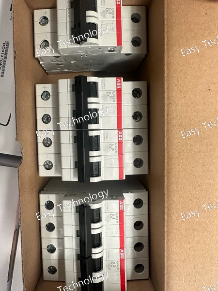
Technical Parameters General Product Type: Miniature Circuit Breaker (MCB) Model: S201‑C1 Series: System pro M compact S200 Number of Poles: 1 (single‑pole) Trip Curve / Characteristic: Type C (thermal‑magnetic) Mounting: DIN rail (IEC 60715 TH35) Terminal Type: Screw terminals Rated Operational Conditions: Residential, commercial, light industrial Electrical Ratings Rated Current (In): 1 A Rated Operational Voltage: 277/480 V AC (UL rating) 230/400 V AC (IEC rating) Rated Insulation Voltage (Ui): 440 V Rated Impulse Withstand Voltage (Uimp): 4 kV Rated Breaking Capacity: 6 kA (IEC/EN 60898‑1) at 230/400 V AC Rated Ultimate Short‑Circuit Breaking Capacity (Icu): Up to 10 kA at lower voltages Rated Service Short‑Circuit Breaking Capacity (Ics): Typical fraction of Icu (e.g., ~7.5 kA) Rated Frequency: 50/60 Hz Utilization Category: Suitable for overload and short‑circuit protection Mechanical & Physical Actuator: Toggle ON/OFF switch Mechanical Life: High (designed for many switching cycles) Terminal Protection: IP20 Panel Protection: Depends on panel enclosure Installation Height: Standard modular width 17.5 mm Approx. Dimensions: ~69 mm (depth) × 17.5 mm (width) × ~88 mm (height) Pollution Degree: 3 Environment Operating Temperature: ‑25 °C to +55 °C ambient Storage Temperature: Typical industrial storage range Compliance Standards: IEC/EN 60898‑1, IEC/EN 60947‑2, UL 1077, CSA C22.2 Features & Applications Thermal‑magnetic trip mechanism for combined overload and short‑circuit protection Compact DIN‑rail mountable design for distribution boards Finger‑safe terminals for enhanced safety in panel use Designed for protection of branch circuits, lighting, receptacles, and small loads Accepts optional accessories (auxiliary contact, shunt trip, alarm contact)
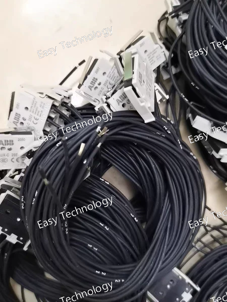
Technical Parameters General Product Type: Auxiliary contact module for molded case circuit breakers (MCCB) Model: AUX‑C 1Q1SY 250 V (T1‑T3) Contact Configuration: 1 Changeover contact (1Q): indicates breaker open/closed position 1 Changeover contact (1SY): indicates trip/fault event Number of Contacts (SPDT): 2 changeover contacts Electrical Ratings Rated Voltage (AC/DC): Up to 250 V AC/DC for signaling circuits Utilization Categories: Suitable for control and signaling use per applicable industrial categories (e.g., AC‑15/DC‑13) Typical rated currents at 250 V AC/DC consistent with auxiliary contact usage Standards Compliance: Designed to meet IEC 60947‑2 and related safety standards Contact Type: Silver alloy or equivalent industrial contact material for reliable switching Compatibility Suitable Breaker Families: ABB Tmax XT series breakers Dedicated slots for T1/T2/T3 accessory positions Mounting Position: Installed externally on the right‑hand side accessory slot of the breaker Pre‑cabled Version: Supplied with approx. 1 m of cable for easy connection Mechanical & Installation Connection: Pre‑wired cable termination for remote connection to control or indicator circuits Mounting: Plug‑in or snap‑on accessory for compatible breaker accessory slot Dimensions & Weight: Compact module that fits within breaker accessory space Operating Orientation: Mounts in the specified accessory slot(s) without modification Environmental Operating Temperature Range: Suitable for typical industrial panel ambient conditions Pollution Degree: Industrial pollutions (IEC categorization) Protection: Front should be protected when installed behind the panel face Functions & Uses Breaker position indication: Shows whether the breaker is closed (ON) or open (OFF) Trip indication: Signals when the breaker has tripped due to overload or fault Remote control feedback: Ideal for PLC, annunciators, control circuits, or automation monitoring AC/DC control systems: Works with both AC and DC control voltages up to 250 V Key Features Dual changeover contacts for combined position and trip status Pre‑wired cable for easy integration Broad voltage compatibility with AC/DC up to 250 V Direct mounting to ABB Tmax XT breaker accessory slot Enhanced monitoring for breaker control and safety logic
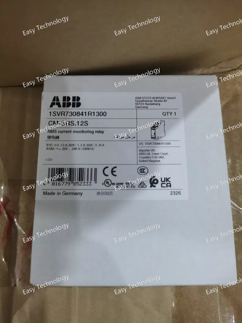
Technical Parameters General Product Type: Current monitoring relay (single‑phase) Model: CM‑SRS.12S Series: CM monitoring relay range Mounting: DIN‑rail mountable Connection Type: Screw connection with double‑chamber cage terminals Monitoring & Measurement Current Measurement Principle: RMS measurement of AC and DC current Measuring Ranges (selectable): 0.3 – 1.5 A 1 – 5 A 3 – 15 A Monitoring Type: Configurable for overcurrent or undercurrent detection Hysteresis: Adjustable (approx. 3 % – 30 % of threshold) Control / Output Output Contact: 1 × Changeover (SPDT) Contact Rating: Up to 250 V AC / 4 A (control/relay output) Contact Function: Relay output for control or signaling Electricals Rated Control Supply Voltage: Wide range versions: 24 – 240 V AC/DC for universal supply 220 – 240 V AC only (control voltage variant) Voltage Type: AC/DC compatible (on universal versions) Operating Phase: Single‑phase current monitoring Performance & Operation Response Types: Overcurrent and undercurrent trip based on set thresholds Adjustment: Threshold and hysteresis adjustable via front controls Status Indication: Relay output state visible via mechanical indicator Mechanical & Physical Dimensions: Width: ~22.5 mm Height: ~85.6 mm Depth: ~103.7 mm Weight: ~0.14 – 0.19 kg depending on variant Housing: Industrial DIN‑rail relay enclosure Environmental Operating Temperature: Suitable for typical industrial ambient temperature ranges Pollution Degree: Designed for industrial environments Protection: Front panel protection per standard enclosure specs Applications Overcurrent and undercurrent monitoring in industrial control panels Protection and alarm systems for motors and loads Automation systems requiring current supervision Control logic interfaces for contactors, breakers, and PLCs **Single‑phase power monitoring in machine and equipment enclosures
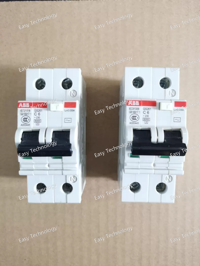
Technical Parameters General Product Type: Residual current circuit breaker with overcurrent protection (RCBO / leakage circuit breaker) Model: GS261‑C6/0.03 Number of Poles: 2 (phase + neutral) Trip Curve: Type C (thermal‑magnetic characteristic) Series: ABB GS261 family Current & Leakage Protection Rated Current (In): 6 A Residual (Leakage) Current Sensitivity (IΔn): 0.03 A (30 mA) for earth‑leakage trip Protection Functions: Overload protection Short‑circuit protection Residual current / earth‑leakage protection Electrical Ratings Rated Operational Voltage: ~230 V AC (single‑phase systems) Frequency: 50 / 60 Hz Rated Breaking Capacity: ~6 kA (typical for small RCBOs) Rated Impulse Withstand Voltage (Uimp): Standard for low‑voltage protective devices Insulation Voltage (Ui): Appropriate for low‑voltage distribution circuits Trip Mechanism Thermal element: protection against prolonged overload Magnetic element: short‑circuit protection Residual current detection: instantaneous trip at leakage > 30 mA Mechanical & Construction Mounting: DIN‑rail (TH35) Terminal Type: Screw terminals for secure wiring Status Indication: ON/OFF and tripped positions on the toggle Mechanical Life: Designed for frequent circuit breaker operations Compact Design: Fits standard modular distribution boards Environmental Operating Temperature: Standard industrial ambient range Pollution Degree: Typical industrial / residential environments Protection Rating: IP20 at terminals; front panel protection depends on installation Applications Personal protection against electric shock Combined overload, short‑circuit, and leakage protection Residential, commercial, and light industrial distribution boards Protection of circuits supplying sockets, lighting, appliances, and equipment
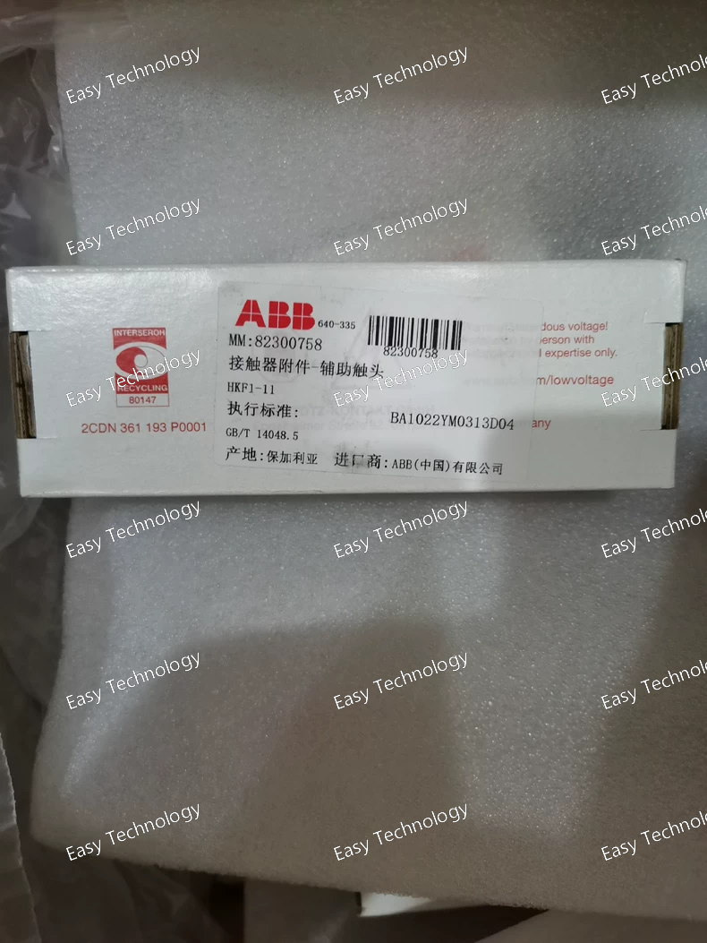
Technical Parameters General Product Type: Auxiliary contact block Model: HKF1‑11 Mounting Type: Front / top mount accessory for compatible starters and contactors Series / Compatibility: Suitable for modular control devices such as MS116, MS132, MS165 manual motor protectors and similar devices Contact Configuration: 1 × Normally Open (NO) + 1 × Normally Closed (NC) Electrical Ratings Rated Insulation Voltage (Ui): ~690 V Rated Operational Voltage (Ue): Suitable for control/auxiliary circuits up to industrial control voltages Rated Operational Current: Typical auxiliary circuit rating suitable for 1–6 A loads (control/feedback circuits) Rated Impulse Withstand Voltage (Uimp): Elevated to standard auxiliary device limits Contact Type: Silver‑based (or equivalent) industrial contact material Mechanical Terminal Connection: Screw terminal type Installation Orientation: Front / top mounting onto starter body Mechanical Life: High cycle capability for frequent auxiliary feedback operations Contact Actuation: Operates with main starter contacts Performance Switching Frequency: Designed for auxiliary control switching load cycles Compatibility With Motor Protection: Works alongside overload/trip feedback and interlock functions Physical & Dimensions Compact Modular Design: Space‑efficient mounting Weight: Lightweight accessory Construction: Durable industrial‑grade plastic and metal parts for robust panel use Environmental Operating Temperature Range: Typical industrial ambient temperatures Pollution Degree: Designed for typical industrial environments Ingress Protection: IP20 at terminals; front mounting in panel can offer additional protection Applications Adding auxiliary feedback to manual motor starters Providing interlocking contacts for control logic circuits Status signaling to PLCs and control systems Enhancing control panel logic with NO/NC feedback Use in motor control centers and industrial automation panels
 TEL: Grace +86 13600179521
  Mail:jilineasyyi@outlook.com
 Q Q:info@hongkongeasy.com
 ADDRESS:Unit 12, 20th Floor, Good View Commercial Centre, 2-16 Garden Street, Mong Kok, Hong Kong
 whats app


