
Industrial Controller
All product are in stock,guaranteed delivery within 3-7 days.


PRODUCT
PICTURE
BRAND
DESCRIBE
STOCK
DOWNLOAD
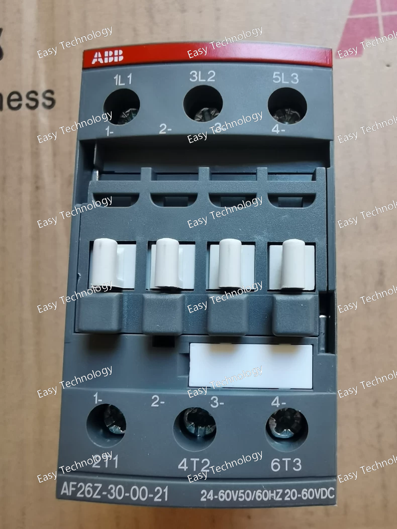
Technical Parameters Parameter Specification Series ABB System Pro M compact® AF Product Type 2-Pole MCB with Z-Curve and Auxiliary Contact Order Code AF26Z-30-00-21 Number of Poles 2-Pole (2P) Rated Current (In) 2 A (The "30" in the code corresponds to a 2A rating in this series' coding system). Tripping Characteristic Z-Curve (Selective) Rated Operational Voltage (Ue) 240/415V AC Rated Insulation Voltage (Ui) 500V AC Rated Impulse Withstand Voltage (Uimp) 6 kV Breaking Capacity (Icn) 10 kA at 400V AC Auxiliary Power Supply 24-60V AC/DC (for internal electronics) Auxiliary Contact 1 NO (Normally Open) Auxiliary Contact Rating Typically 250V AC, 5A Rated Frequency 50/60 Hz Terminals Cage clamp terminals for conductors (main): 1 - 25 mm² / (auxiliary): 0.2 - 2.5 mm² Terminal Torque 2.0 N·m (main), 0.5 N·m (auxiliary) Mounting DIN Rail (35mm) Electrical Durability ≥ 10,000 operations at In Mechanical Durability ≥ 20,000 operations Standards Compliance IEC/EN 60947-1, IEC/EN 60947-2 Ambient Temperature -25°C to +60°C (Operation) Trip Time Instantaneous trip range: Approx. 4A to 6A (2-3 x In) within milliseconds.
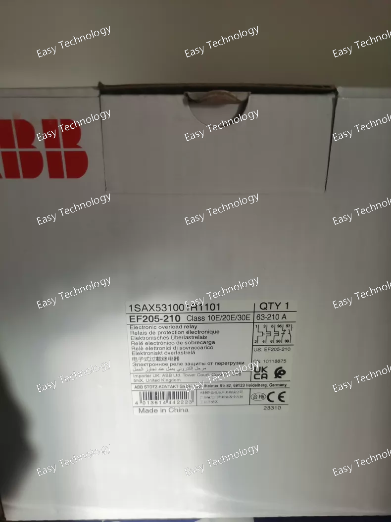
Technical Parameters Parameter Specification Series ABB EF200 Series (Residual Current Monitoring Relays) Product Type Residual Current Relay / Earth Fault Relay Order Code EF205-210 Rated Residual Operating Current (IΔn) 100 mA (as indicated by the "-210" suffix) Residual Current Type Type A (for sinusoidal AC and pulsating DC residual currents) Rated Operational Voltage (Aux Supply - Ue) Typically 230V AC (must verify, some models are line-powered from the monitored circuit or have separate supply terminals). Auxiliary Supply Voltage Range Common range: 230V AC ±10%, 50/60 Hz. (Some versions may support 24-240V AC/DC). Crucial to check datasheet. Output Contact 1 Changeover (SPDT) Relay Contact for signaling or triggering an external shunt trip release. Contact Rating Typically 250V AC, 5A (sufficient to energize a standard shunt trip coil). Operating Time at IΔn < 0.3 seconds (Standard for Type A). Trip Delay Usually instantaneous, but some models may have a small fixed or adjustable delay. Test Function Manual test button to verify functionality by simulating a residual current. Status Indication LED indicator (often red/green) to show "Power ON" and "Tripped" status. Mounting Snap-on mounting on 35mm DIN Rail. Module Width 1 Module (18mm) or 2 Modules, depending on design. Connection Terminals Screw terminals. Terminals for: Auxiliary Power (L, N), Signal Output, and connections to the external Core Balance Current Transformer (CBCT) or internal sensing for direct connection models. Standards Compliance IEC/EN 61008-1, IEC/EN 61009-1 (in conjunction with the associated circuit breaker), IEC/EN 60947-2 Annex M. Ambient Temperature -25°C to +60°C (Operation)
Technical Parameters Parameter Specification Series / Product Type ABB Masterpact (MP) Series / Rotary Disconnect Switch (Load Break Switch) Order Code MP3-30R Number of Poles 3-Pole (3P) Rated Operational Current (Ie) 30 A (at 400V AC, AC-22A / AC-23A utilization category) Rated Operational Voltage (Ue) 690V AC Rated Insulation Voltage (Ui) 1000V AC Rated Impulse Withstand Voltage (Uimp) 12 kV Rated Short-Time Withstand Current (Icw) Typically 5 kA for 1 second (Must verify from specific datasheet. This is its ability to withstand a fault current without opening). Making & Breaking Capacity At 415V AC: Typically 30 A for normal service breaking (AC-23A). Utilization Category AC-22A (Switching of mixed resistive and inductive loads) AC-23A (Switching of motor loads or other highly inductive loads) Mechanical Life Typically > 10,000 operations Electrical Life Typically > 5,000 operations at rated current Operation Manual rotary handle (ON-OFF). Handle can be padlocked in the OFF position for safety lockout/tagout (LOTO). Mounting Fixed mounting for panel assembly. Connection Suitable for cable or busbar connection. Auxiliary Contacts Not included as standard. Often available as optional add-on modules (e.g., 1NO+1NC) for remote signaling of switch position. Standards Compliance IEC/EN 60947-1, IEC/EN 60947-3 (Specifically for switches, disconnectors, switch-disconnectors, and fuse-combination units) Ambient Temperature -25°C to +70°C (Operation)
Technical Parameters Parameter Specification Series ABB Form 2a / Tmax (S2C Series) Product Type Moulded Case Circuit Breaker (MCCB) with Fixed Thermal-Magnetic Trip Unit Order Code S2C-H6R Number of Poles 3-Pole Rated Current (In) 100 A (The "6" in H6R often corresponds to a frame size rating, with 100A being a standard value for this frame). Rated Ultimate Short-Circuit Breaking Capacity (Icu) Typically 50 kA or 70 kA at 415V AC (This is the key feature of the "H"-rated version. Must confirm with local catalog). Rated Service Short-Circuit Breaking Capacity (Ics) Typically 100% of Icu for this series (e.g., 50 kA). Trip Unit Type Fixed Thermal-Magnetic (H-Type) Overload Protection (Ir) Fixed at In (100 A). Thermal adjustment is typically not available on "R" versions. Short-Circuit Protection (Im) Fixed High Magnetic Setting. Typically set at 12 x In (1200 A) or higher. Non-adjustable. Rated Operational Voltage (Ue) 690V AC Rated Insulation Voltage (Ui) 1000V AC Rated Impulse Withstand Voltage (Uimp) 12 kV Rated Frequency 50/60 Hz Electrical Durability Up to 8,000 operations at In Mechanical Durability Up to 20,000 operations Mounting Fixed Mounting (for panel assembly) Connection Front and/or rear connection. Suitable for busbar or cable connection. Standards Compliance IEC/EN 60947-1, IEC/EN 60947-2 Operating Ambient Temperature -25°C to +70°C (Derating may apply above 40°C) Accessories Compatible with a wide range of ABB accessories: auxiliary contacts (OF, SD), shunt trips, undervoltage releases, handle extensions, etc.
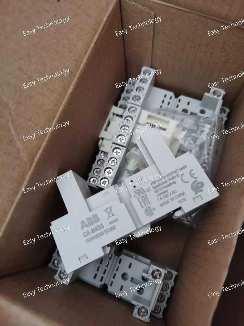
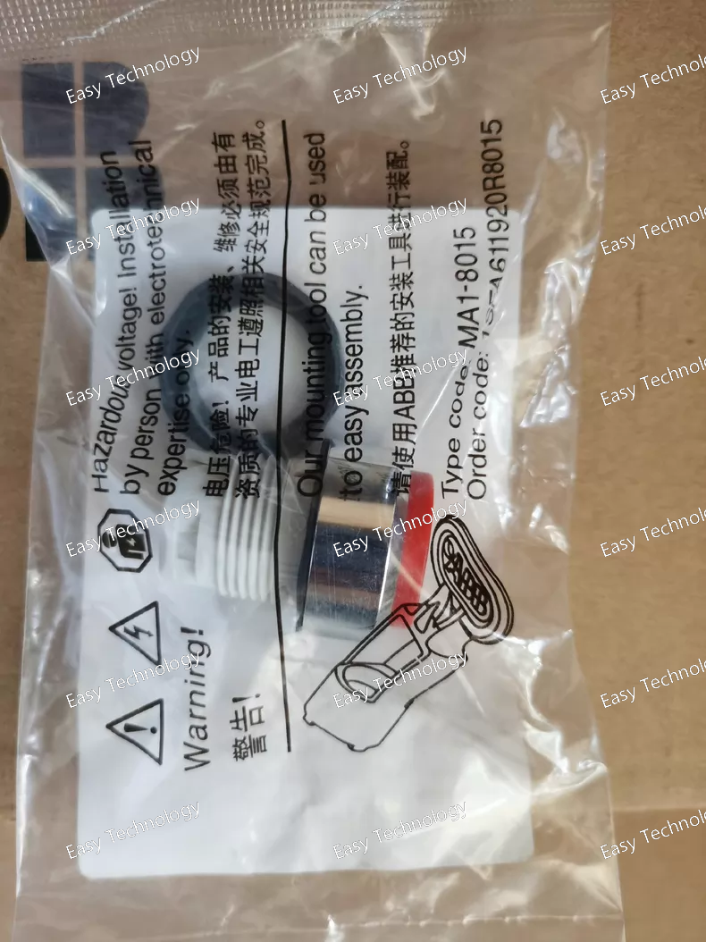
Technical Parameters Parameter Specification Series ABB CR-M Series (Industrial Control Devices) Product Type Emergency Stop Push Button (Mushroom Head, Twist-to-Release) Order Code CR-M4SS Actuator Type Large Mushroom Head (Typically ≥ 40mm diameter) Actuator Material Solid Stainless Steel (Corrosion-resistant, durable) Actuator Color Red with Yellow background ring (Standard for E-Stop per IEC 60204-1) Contact Blocks Sold separately. Compatible with CR-M series contact blocks (e.g., CR-MXT). Typically requires at least 1 NO (Normally Open) and 1 NC (Normally Closed) contact block with positive-guided (force-guided) mechanism for safety circuits. Contact Rating Depends on the attached contact block. Typical: Up to 600V AC, 10A. Mechanical Life Very high, typically > 1,000,000 operations. Electrical Life Depends on contact block and load. Operation Mode Push to activate (lock), Twist clockwise to release and reset. Protection Degree (IP Rating) Front side (actuator): Typically IP65 or higher (Dust-tight and protected against water jets). Behind panel depends on enclosure. Mounting Panel mounting via a mounting collar from the front. Requires a round panel cutout (specific diameter, e.g., 22mm or 30mm). Mounting Hole Diameter Typically 22.5mm or 30.5mm (Must confirm based on exact model). Terminal Connection Screw terminals on the attached contact block(s). Standards Compliance IEC/EN 60947-5-1, IEC/EN 60947-5-5 (for emergency stop function), IEC 60204-1 (Safety of machinery), ISO 13850. Safety Integrity When used with appropriate positively guided contact blocks and safety relays, can contribute to Safety Category (e.g., Cat. 3/4 per ISO 13849-1, SIL 2/3 per IEC 62061). Ambient Temperature -25°C to +70°C (Operation)
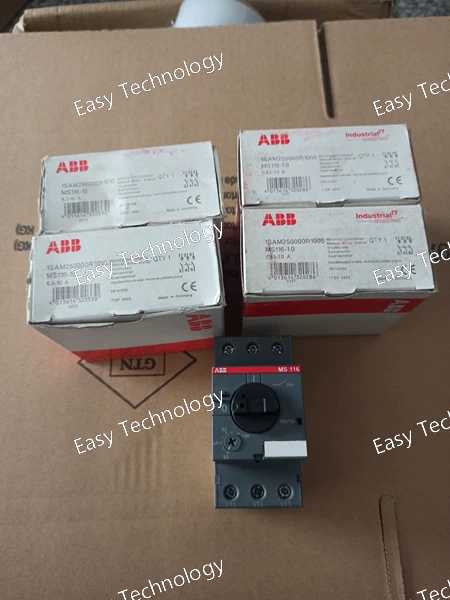
Technical Parameters Parameter Specification Series ABB MS116 Product Type Miniature Circuit Breaker (MCB) Order Code / Article Number MS116-0.63 Number of Poles 1-Pole (1P) Rated Current (In) 0.63 A Tripping Characteristic C-Curve (Typical for this series. Provides instantaneous trip between 5-10x In, i.e., ~3.15A to 6.3A). Rated Operational Voltage (Ue) 240/415V AC Rated Insulation Voltage (Ui) 440V AC Rated Impulse Withstand Voltage (Uimp) 4 kV Rated Frequency 50/60 Hz Breaking Capacity Typically 6 kA (at 400V AC, according to IEC/EN 60898-1) Terminals Screw-type terminals, suitable for conductors typically up to 16 mm² (please verify for 0.63A model). Terminal Torque 1.5 - 2.0 N·m (Standard) Mounting DIN Rail (35mm) mounting Electrical Durability ≥ 10,000 operations Mechanical Durability ≥ 20,000 operations Standards Compliance IEC/EN 60898-1 (Primary standard) & IEC/EN 60947-2 (For industrial applications) Ambient Temperature -25°C to +55°C (for calibration), operation up to +60°C Weight Approx. 0.08 kg
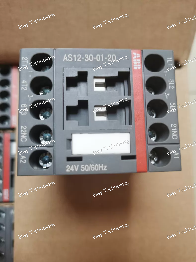
Parameter Specification Series ABB System Pro M compact® (Accessory for S200 series) Product Type Push-to-Test Signal Lamp / Indicator Light (Monochrome) Order Code AS12-30-01-20 Lens Color Single Color (Specific color如 Red, Green, Yellow, etc. is defined by "-30-". Red is common for alarms/power.) Lens Type Flat or domed, monochrome. Voltage Rating For lamp/LED: Common ratings are 24V AC/DC, 48V AC/DC, 110V AC, 230V AC (e.g., "-01-" may correspond to 230V AC). Must be matched to the control circuit voltage. Light Source Traditionally an incandescent bulb (e.g., 230V, 1-2W). Modern variants or replacement inserts may use long-life LEDs. Push-to-Test Function Yes. Pressing the lens activates the lamp independently of the main terminals, for functional testing. Terminals Screw-clamp terminals for reliable connection. Wiring Typically 2 or 3 terminals: L1 (Phase/Signal), N (Neutral/Common), sometimes a separate Test terminal. Mounting Snap-on mounting on 35mm DIN rail. Module Width 1 module (18mm wide, based on "-20" suffix). Degree of Protection (IP Rating) IP40 (front side) when mounted in an enclosure. Ambient Temperature -25°C to +60°C (operation) Standards Compliance IEC/EN 60617, UL 508, CSA C22.2 No. 14
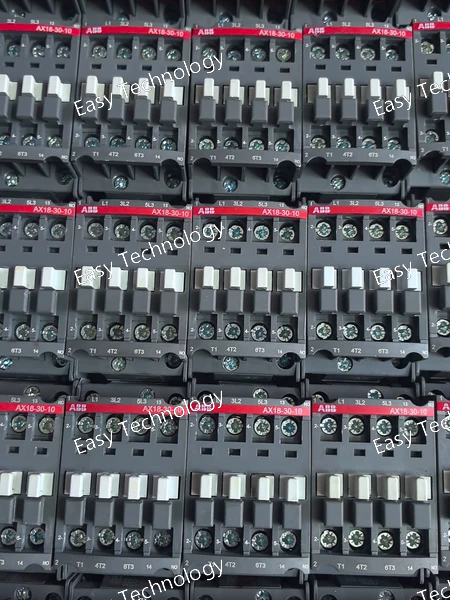
Technical Parameters Parameter Specification Series / Product Type ABB AX Series Manual Motor Starter / Protector Order Code AX18-30-10 Poles 3-Pole (for three-phase motors) Utilization Category AC-3 (Squirrel cage motor: starting, switching off) Rated Operational Current (Ie) Up to 18 A (This is the maximum current-carrying capacity of the main contacts. The "18" in AX18 denotes this.) Rated Thermal Current (Ith) Adjustable Range: 0.10 - 18 A (The "30-10" likely refers to the specific adjustment dial range, e.g., 0.30 - 10 A for the thermal element. The exact sub-range must be confirmed from the label.) Thermal Overload Setting Continuously adjustable via a rotary dial within the specified sub-range (e.g., 0.3 to 10A). Short-Circuit Protection Magnetic instantaneous trip, typically set at 12 x Ith or a fixed value (e.g., ~200A for this frame size). Rated Operational Voltage (Ue) 690V AC Rated Insulation Voltage (Ui) 690V AC Control Voltage Not applicable - manually operated. Rated Short-Circuit Breaking Capacity (Icu/Ics) Typically 6 kA or 10 kA at 400V AC (specific value depends on certification). Ambient Temperature Compensation Yes, built into the bimetal mechanism. Trip Class Class 10 (The "10" in "30-10" often indicates this). This means it will trip within 10 seconds at 720% of the set current. Auxiliary Contacts None on the basic unit. Some models offer optional, add-on auxiliary contact blocks (e.g., 1NO+1NC) for signaling. Mounting Snap-on mounting for DIN Rail (35mm) or screw mounting. Connection Terminals Screw terminals suitable for solid and stranded conductors. Standards Compliance IEC/EN 60947-1, IEC/EN 60947-4-1, UL 508, CSA C22.2 No. 14. Degree of Protection (IP Rating) IP00 (component). Requires an enclosure for IP20 or higher. Ambient Temperature -25°C to +60°C (operation)
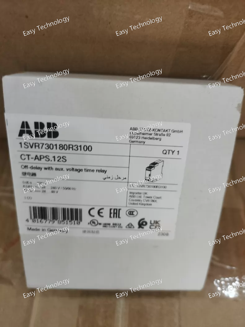
Technical Parameters Parameter Specification Product Type Split-Core Current Transformer (Clamp-on Type) ABB Order Code CT-APS.12S Core Type Split-Core / Clamp-On Primary Current (Ipn) e.g., 100A, 150A, 200A, 300A (*This is a critical variable. The exact value must be confirmed from the specific label or datasheet. 12S often correlates with a specific ratio like 100/5A or 150/5A.*) Secondary Current (Isn) Typically 5 A or 1 A (Standard for measurement) Accuracy Class Typically 1.0 or 0.5 (at specified burden, for measurement) Rated Frequency 50/60 Hz Rated Thermal Short-Time Current (Ith) e.g., 60 x Isn for 1 second Rated Dynamic Current (Idyn) e.g., 2.5 x Ith Rated Insulation Voltage 0.72 kV (for low-voltage systems up to 600V AC) Rated Burden e.g., 5 VA or 2.5 VA (Standard burdens: 2.5VA, 5VA, 10VA) Operating Temperature Range -25°C to +70°C Aperture (Inner Diameter) e.g., 25mm, 30mm, or 35mm (Must be large enough to fit the conductor being measured) Mounting Typically includes mounting holes or brackets for fixed installation. Can also be used as a portable clamp. Output Connection Standard screw terminals for secondary wiring. Standards Compliance IEC 61869-1, IEC 61869-2 Safety Standard IEC/EN 61010-1
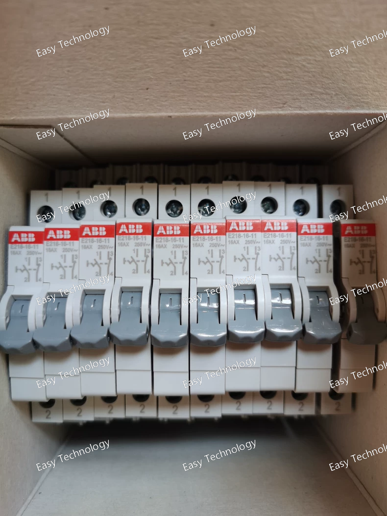
Technical Parameters Parameter Specification Series ABB Domae / E200 (Residential Series) Product Type Residual Current Circuit Breaker with Overcurrent Protection (RCBO) Order Code / Article Number E218-16-11 Number of Poles 2-Pole (2P) – Both phase and neutral are switched and protected. Rated Current (In) 16 A Overcurrent Tripping Characteristic C-Curve Rated Residual Operating Current (IΔn) 30 mA Residual Current Type Type AC (for sinusoidal alternating residual currents only) Rated Operational Voltage (Ue) 230V AC (Single-Phase) Rated Frequency 50/60 Hz Rated Short-Circuit Breaking Capacity (Icn) 6 kA (Typical for this series) Residual Current Breaking Capacity 1000 A Trip Time at IΔn ≤ 0.3 seconds Trip Time at 5x IΔn (150 mA) ≤ 0.04 seconds Rated Insulation Voltage (Ui) 500V AC Rated Impulse Withstand Voltage (Uimp) 4 kV Standards Compliance IEC/EN 61009-1 (Core standard for RCBOs) Terminals Suitable for solid and stranded copper conductors. Line/N Load Terminals: 1 - 25 mm² / Line/N Supply Terminals: 1 - 16 mm² Terminal Torque 2.0 N·m Mounting DIN Rail (35mm) mounting Mechanical & Electrical Durability ≥ 10,000 operating cycles Ambient Temperature (Operation) -25°C to +55°C (for calibration) Test Button Yes (Yellow), for periodic manual testing of the residual current mechanism. Status Indication Clear ON/OFF (I/O) flag. The handle moves to a mid-position upon tripping, indicating a fault (overcurrent or residual current).
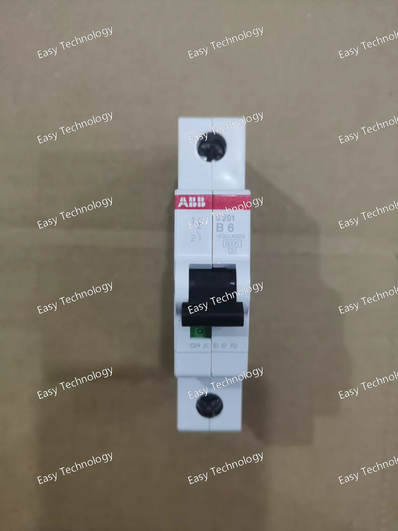
Parameter Specification Series System Pro M compact® S200 Product Type Miniature Circuit Breaker (MCB) Order Code / Article Number S201-B6 Number of Poles 1-Pole (1P) Rated Current (In) 6 A Tripping Characteristic B-Curve Breaking Capacity 6 kA (IEC/EN 60898-1) Rated Operational Voltage (Ue) 230/400V AC Rated Insulation Voltage (Ui) 440V AC Rated Impulse Withstand Voltage (Uimp) 4 kV Rated Frequency 50/60 Hz Standards IEC/EN 60898-1 (Primary standard for household & similar installations) Also complies with IEC/EN 60947-2 (Industrial use) Terminals Cage clamp terminals suitable for solid and stranded conductors, 1 - 25 mm² / AWG 24 - 4. Terminal Torque 2.0 - 2.5 N·m (for main terminals) Mounting DIN Rail (35mm) mounting Electrical Durability 20,000 mechanical operations 10,000 electrical operations at rated current Mechanical Durability 20,000 operations Ambient Temperature -25°C to +55°C (for calibration), up to +60°C (operation with possible derating) Pollution Degree 2 Protection Degree (IP) IP20 (when mounted in an enclosure) Weight Approx. 0.1 kg
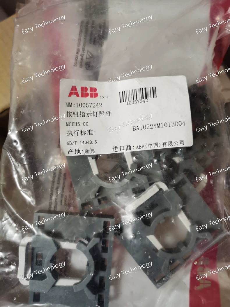
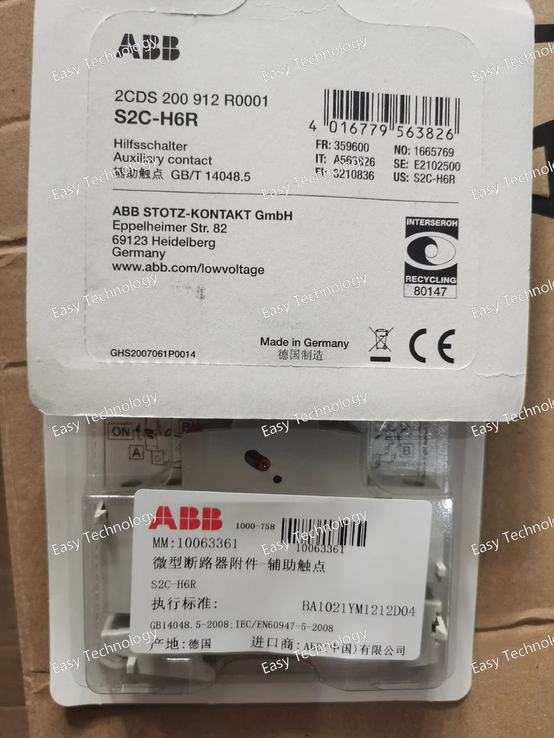
Parameter Specification Product Type Auxiliary Contact Block (Accessory) ABB Order Code / Article Number MCBH5-00 Compatible Series ABB System Pro M compact® S200, S200U, S200P, S200M, S280 UC, and corresponding RCCBs (e.g., DS200) Contact Configuration 1 Changeover (1 CO) / 1 SPDT (Single Pole Double Throw) Contact Function Mechanically linked to breaker position. One contact is normally closed (NC) and the other is normally open (NO), relative to the breaker’s “ON” position. Rated Operational Voltage (Ue) 250V AC, 400V AC Rated Insulation Voltage (Ui) 500V AC Rated Impulse Withstand Voltage (Uimp) 6 kV Rated Thermal Current (Ith) 10 A Utilization Categories AC-14: Control of small electromagnetic loads (< 72 VA) AC-15: Control of electromagnetic loads (> 72 VA) DC-13: Control of DC electromagnetic loads Switching Capacity At 230V AC: 6 A (AC-15) At 400V AC: 3 A (AC-15) At 24V DC: 6 A (DC-13) Electrical Durability Minimum 10,000 operating cycles (at rated operational current) Mechanical Durability Minimum 30,000 operating cycles Mounting Method Snap-on / Plug-in attachment directly to the side of the compatible breaker. Can be mounted on either the left or right side. Connection Screw-type terminals for conductors up to 2.5 mm² Terminal Torque 0.5 - 0.6 N·m Standards Compliance IEC/EN 60947-5-1 Ambient Temperature -25°C to +70°C (Operation) Pollution Degree 2
 TEL: Grace +86 13600179521
  Mail:jilineasyyi@outlook.com
 Q Q:info@hongkongeasy.com
 ADDRESS:Unit 12, 20th Floor, Good View Commercial Centre, 2-16 Garden Street, Mong Kok, Hong Kong
 whats app


