
Industrial Controller
All product are in stock,guaranteed delivery within 3-7 days.


PRODUCT
PICTURE
BRAND
DESCRIBE
STOCK
DOWNLOAD
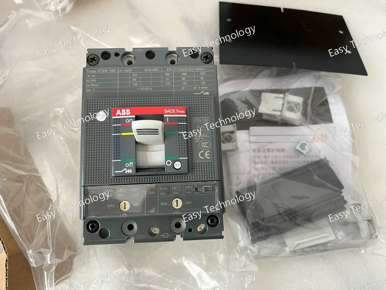
Technical Parameters Parameter / Feature Specification Model / Type XT2N 160 TMA63/630 3P FF MCCB Poles 3‑pole (3P) Trip Unit Type Thermal‑magnetic (TMA) Adjustable Current Range 63 A nominal, adjustable up to 630 A depending on setting Rated Operational Voltage Up to 690 V AC Insulation / Impulse Withstand Voltage 690 V AC / 1000 V impulse withstand Short‑Circuit Breaking Capacity e.g., 36 kA at 400 V AC; higher at lower voltages depending on variant Frame / Device Size XT2 160 frame class Terminals / Connection Front terminals (FF), fixed mounting Mounting DIN‑rail or panel mounting (fixed) Typical Applications Industrial / commercial low‑voltage distribution, motor and equipment protection, branch‑circuit protection
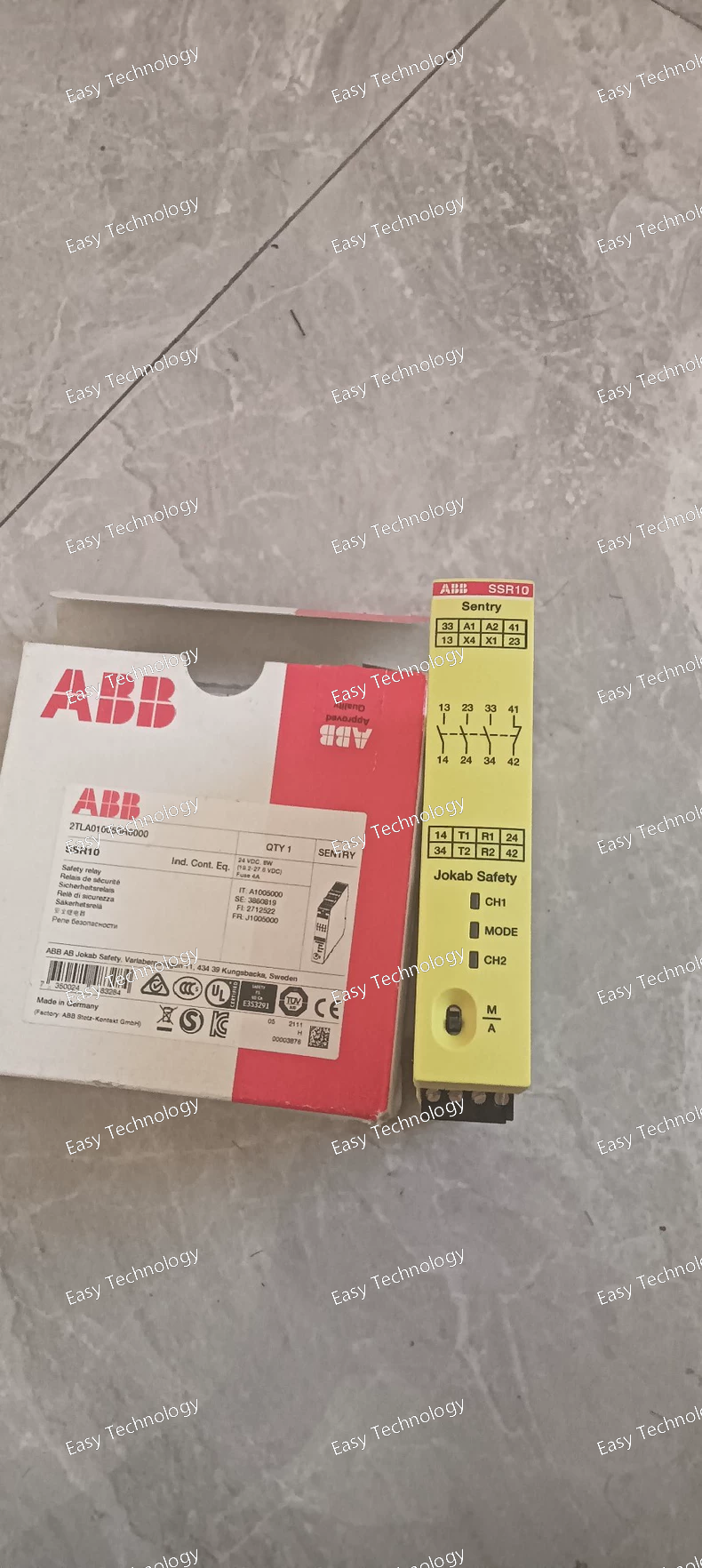
Technical Parameters Parameter / Feature Specification Model / Type SENTRY SSR10 (2TLA010050R0000) Supply Voltage 24 V DC Input Monitoring Single‑channel or dual‑channel safety devices, including OSSD‑output devices Reset Mode Manual or automatic (selectable) Safety Output Contacts 3 × Normally‑Open (NO) + 1 × Normally‑Closed (NC) Contact Rating Up to 6 A for resistive DC or AC loads Mounting / Wiring DIN‑rail mountable; screw‑terminal connections Dimensions (W × H × D) 22.5 mm × 120 mm × 120 mm Protection IP20 (housing and terminals) Safety Performance Performance Level e (PL e), suitable for high-category safety applications Typical Applications Emergency‑stop circuits, guard interlocks, light‑curtain monitoring, general machine‑safety control
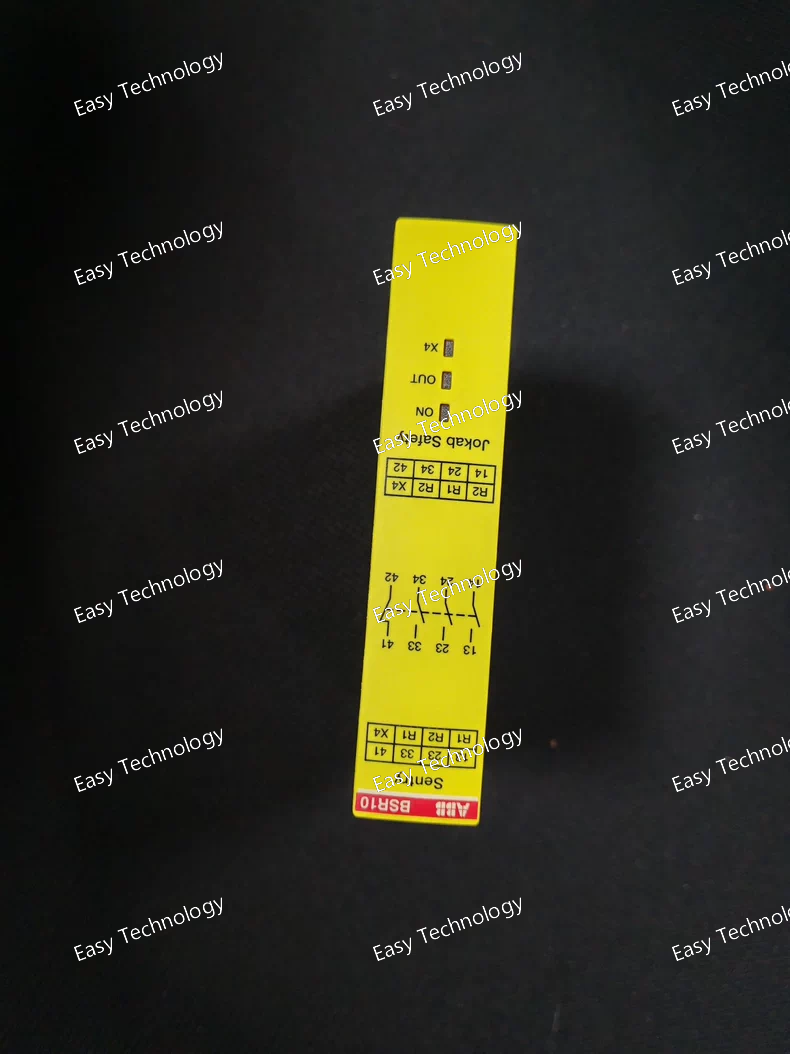
Technical Parameters Parameter / Feature Specification / Detail Model / Series SENTRY BSR10 — 2TLA010040R0000 Supply Voltage (Us) 24 V DC Output Contacts (Safety Outputs) 3 × Normally‑Open (NO) + 1 × Normally‑Closed (NC) (i.e. 3NO + 1NC) Rated Output Current ~ 5 A AC‑15 (typical), ~ 6 A DC‑13 (resistive DC) per contact Mounting / Connection 35 mm DIN‑rail mountable; screw terminal connections (supports standard wiring) Protection / Enclosure Rating IP20 (standard for housing/terminals) Dimensions (W × H × D) 22.5 mm × 120 mm × 120 mm Net Weight ~ 0.19 kg Safety Category / Performance Level Suitable for safety‑critical applications; can be used to meet high safety requirements when used properly (e.g. as part of safety circuits) Typical Use / Application Emergency‑stop circuits, basic safety‑device monitoring, output expansion for safety relays / safety PLCs, simple machine safety control, safety output doubling / expansion
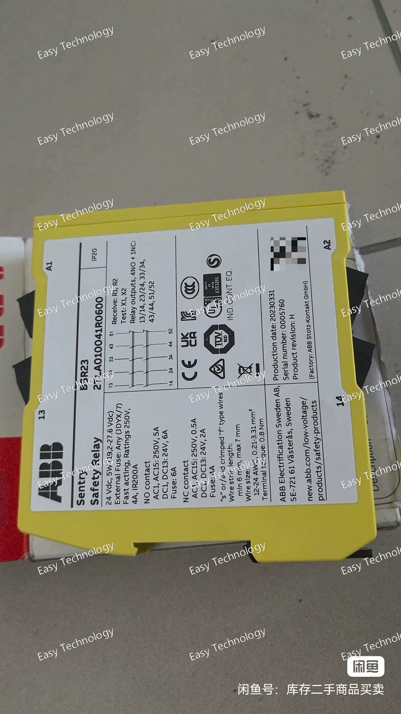
Technical Parameters Parameter / Feature Specification / Detail Model / Series Sentry BSR23 — 2TLA010041R0600 Supply Voltage 24 V DC Function Safety expansion relay (provides additional safe outputs) Safety Output Contacts 4 × Normally‑Open (NO) + 1 × Normally‑Closed (NC) relay contacts (4NO + 1NC) Contact Current / Load Capacity Rated for typical control loads; supports up to 5 A (AC‑15) / 6 A (DC‑13) operational current on contacts depending on load type Wiring / Connection Screw terminals; supports solid or ferruled conductors; wire cross‑section typical: 0.2–3.3 mm² (single) or 0.2–1.5 mm² (double) depending on terminal configuration Mounting DIN‑rail (TH35) mounting (standard control‑panel rail) Enclosure / Protection IP20 (housing/terminals) Dimensions (W × H × D) 22.5 mm × 120 mm × 120 mm Weight ~ 0.20 kg Safety Performance / Level Designed as expansion relay associated with safety circuits; can be used where safety system requires expansion of outputs; used in safety architectures compliant with high‑level safety requirements when correctly integrated Intended Use / Application Expanding number of safe outputs for safety relays / safety PLCs — controlling multiple contactors/actuators from a single safety input, suitable for industrial machinery control cabinets
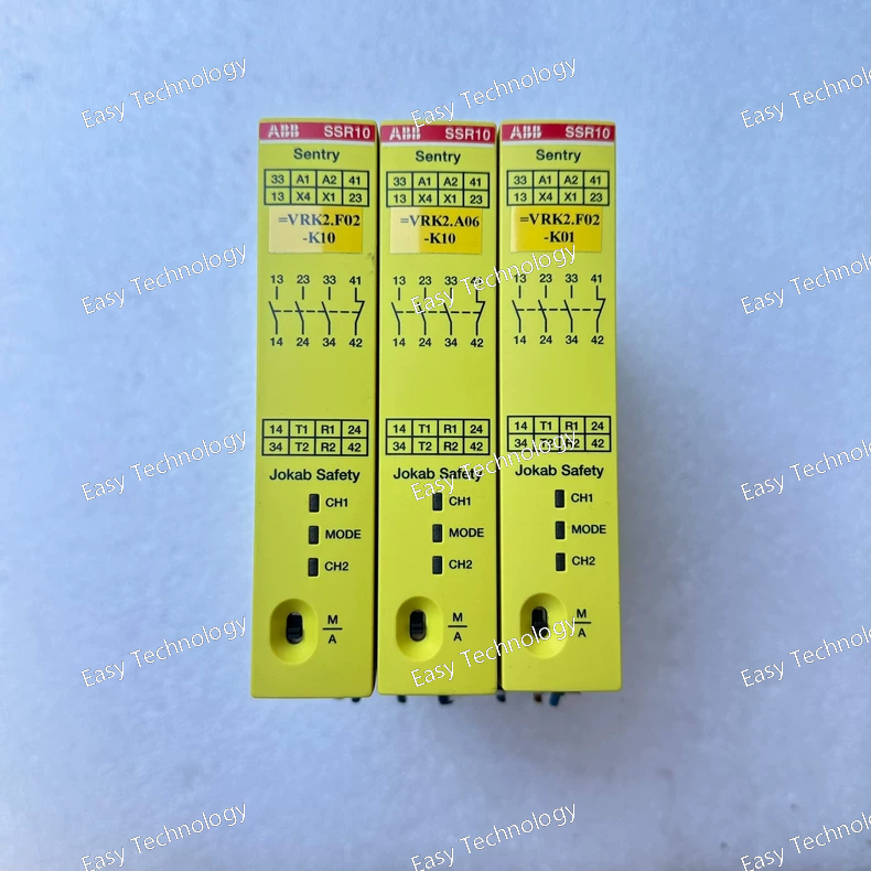
Technical Parameters Parameter / Feature Specification Model / Type SSR10 — Safety relay (2TLA010050R0000) Supply Voltage 24 V DC Input Monitoring Single‑channel or dual‑channel safety devices, including OSSD‑output devices Reset Mode Manual or automatic (selectable) Safety Output Contacts 3 × Normally‑Open (NO) + 1 × Normally‑Closed (NC) Contact Rating Up to 6 A for resistive DC or AC loads Mounting / Wiring DIN‑rail mountable; screw‑terminal connections Dimensions (W × H × D) 22.5 mm × 120 mm × 120 mm Protection IP20 (housing and terminals) Safety Performance Performance Level e (PL e), suitable for high-category safety applications Typical Applications Emergency‑stop circuits, guard interlocks, light‑curtain monitoring, general machine‑safety control
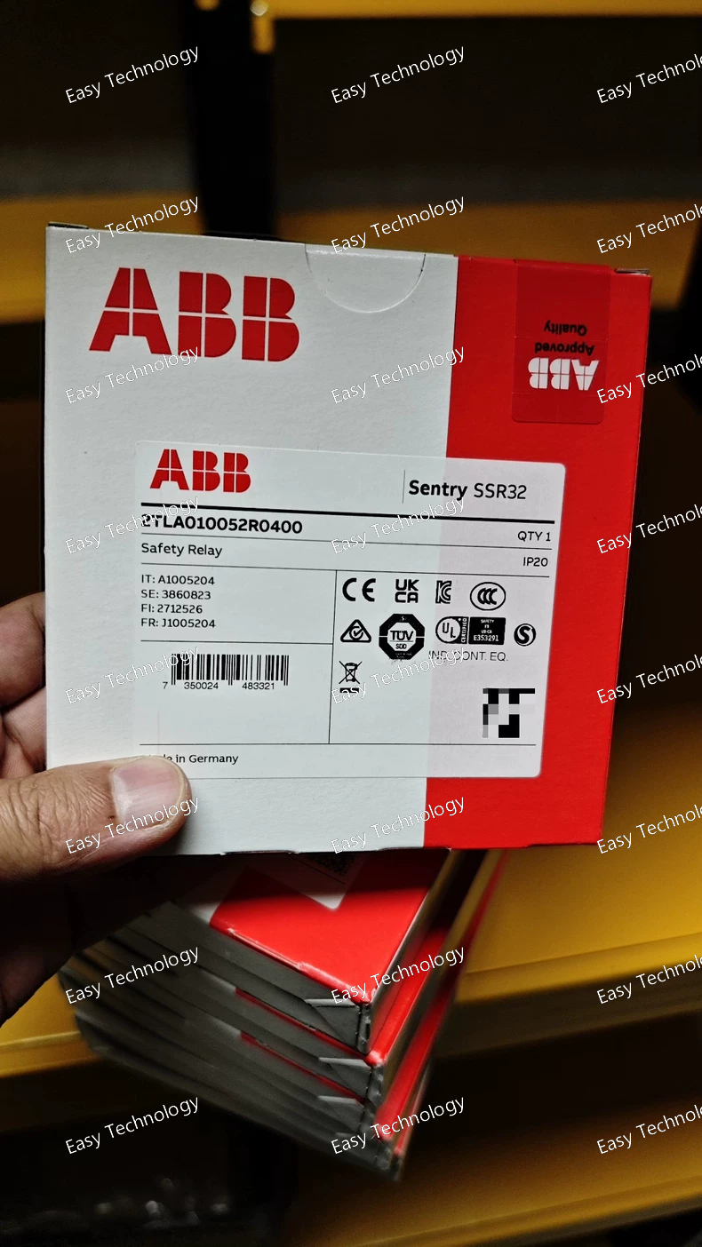
Technical Parameters Parameter / Feature Specification / Detail Product / Model SSR32 — 2TLA010052R0400 Supply Voltage (Us) 24 V DC Input Monitoring Safety devices with contacts (1‑ or 2‑channel), or safety devices with OSSD outputs Reset Mode Manual or automatic reset (selectable via front‑panel switch) Safety Output Contacts 2 × Normally‑Open (NO) (instant) + 2 × Normally‑Open (NO, delayed OFF) OFF‑Delay for Delayed Outputs 0.5 seconds Output Current Rating / Load Capacity Up to 3 A (AC‑15 / DC‑13 rating) per output contact Voltage Rating of Contacts Suitable for typical AC/DC control circuits (e.g. up to 250 V AC nominal) Terminal Type / Wiring Capacity Screw terminals; wire capacity (solid or ferruled) 0.2 … 3.3 mm² (depending on terminal) Mounting 35 mm DIN‑rail (TH35) mountable Dimensions (W × H × D) 22.5 mm × 120 mm × 120 mm Weight ~ 0.207 kg Protection / Enclosure Rating Terminals/enclosure: IP20 Supported Functions Monitoring of safety circuit (E‑stop, gate switches, OSSD devices, etc.), delayed/off‑delay outputs, automatic/manual reset selection, single or dual‑channel input wiring Safety Performance / Standard Compliance Up to Performance Level e (PL e) / SIL 3 (when used in correct safety circuit) Typical Applications Safety‑switch monitoring, light‑curtain / OSSD safety devices, emergency‑stop circuits, interlock guard doors/gates, simple safety circuits with delayed stop output, general machine‑safety control
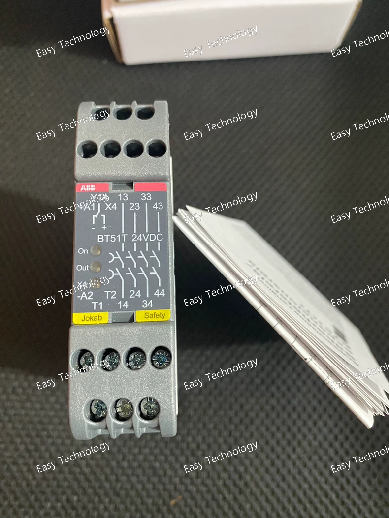
Technical Parameters Parameter / Feature Specification / Detail Product / Model BT51T 24DC Safety Relay — 2TLA010033R3000 Supply Voltage (Us) 24 V DC (±15% / –25%) Power Consumption ≈ 1.4 W (typical), up to 1.8 W Safety Outputs 4 × Normally‑Open (4 NO) relay contacts Contact Rating (Resistive Load) 6 A @ 250 V AC / 1500 VA max; 6 A @ 24 V DC / 150 W max Inductive / AC‑15 / DC‑13 Load Capacity AC‑15 (240 V AC): 2 A; DC‑13 (24 V DC): 1 A Maximum Total Switching Capacity (All Contacts) 12 A (distributed across outputs) Minimum Switching Load 10 mA @ 10 V (if load per contact ≤ 100 mA) Contact Material Silver with gold flash (Ag + Au‑flash) Output Delay (Drop / Soft‑Stop) Selectable 0 – 1.5 seconds Input / Reset / Supervision Single‑ or dual‑channel safety inputs; supervised test/reset input for checking contactor/valve drop before restart Mounting / Terminals 35 mm DIN‑rail mounting; screw‑clamp terminals (with detachable/quick‑release connector blocks) Dimensions (W × H × D) 22.5 mm × 84 mm × 120 mm Protection / Housing Rating Housing: IP40; Terminals: IP20 (per IEC 60529) Environmental / Operating Conditions Operating temperature: –10 °C to +55 °C; Pollution degree 2; Impulse withstand voltage 2.5 kV Safety Performance / Standards Safety Category 4, Performance Level e (PL e) per EN ISO 13849‑1; SIL 3 per IEC 62061 when used in compliant safety circuits Status Indication LEDs for supply, relay, and output state Typical Use Cases Emergency‑stop circuits; safety‑switch / interlock monitoring; safety‑gate / hatch guard; safety‑output expansion; delayed safe stop (soft‑stop) control; industrial machine safety.
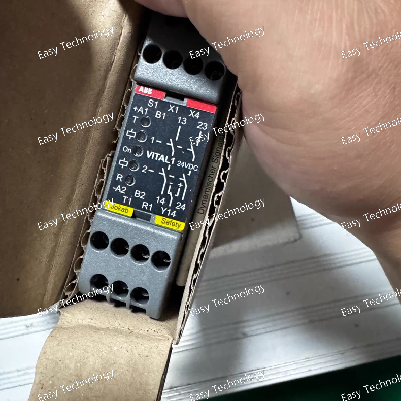
Technical Parameters / Key Specifications Parameter / Feature Specification / Detail Model / Name Vital 1 — 2TLA020052R1000 Supply Voltage (Us) 24 V DC Input Type Single‑channel dynamic (“DYNlink”) input, designed for dynamic safety sensors Supported Devices Compatible with DYNlink safety sensors (e.g. light‑curtains, safety switches, etc.) — up to ~30 sensors in series Reset Mode Manual‑supervised or automatic reset (configurable) Safety Output Contacts 2 × Normally‑Open (2 NO) safety‑rated relay contacts Information / Auxiliary Output 1 information (status) output — for reset indication / status signalling to PLC or other control system Safety Level / Certification Safety Category 4, Performance Level (PL) e per EN ISO 13849‑1; SIL 3 per IEC 61508 (when used with approved sensors) Enclosure / Mounting DIN‑rail mounting; width 22.5 mm; detachable screw‑terminal blocks (connector blocks) Operating Temperature Range –10 °C to +55 °C Protection Class / IP Rating Housing: IP40, Terminals / connection block: IP20 Other Features LED diagnostics (power, dynamic signal, outputs), reduced wiring with serial connection, easy installation without programming, compact size for control cabinets
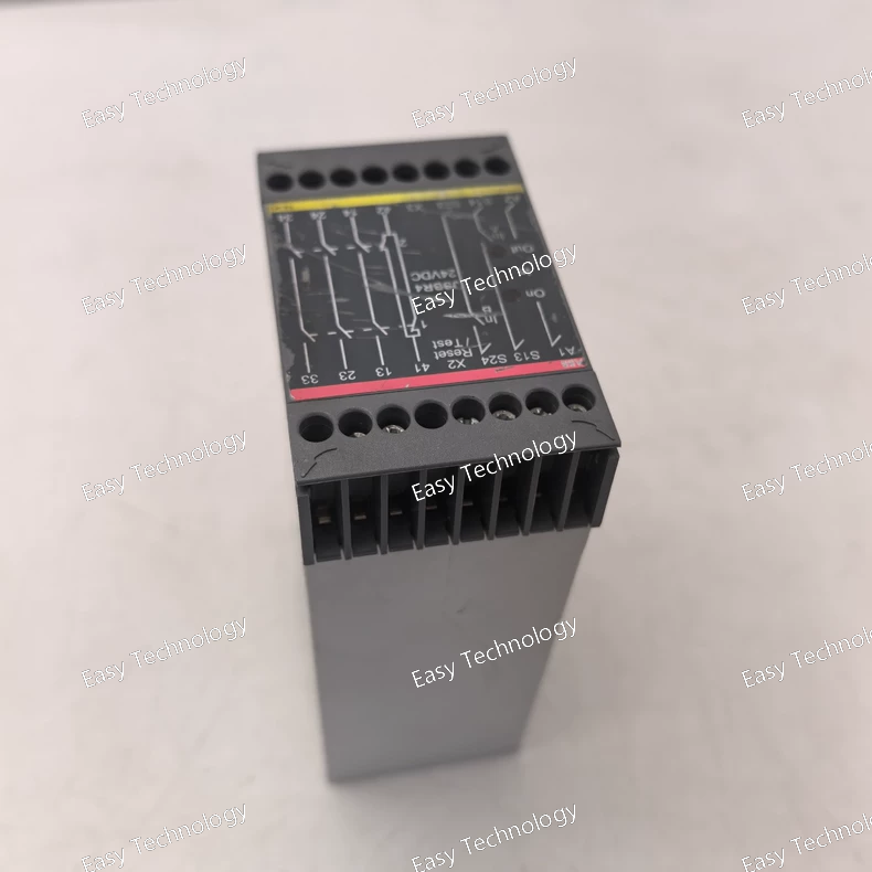
Technical Parameters Parameter / Feature Specification / Detail Model / Series JSBR4 24 VDC Safety Relay (2TLA010002R0000) Supply Voltage (Coil / Control) 24 V DC Output Contact Configuration 3 × Normally‑Open (NO) + 1 × Normally‑Closed (NC) relay contacts (3NO / 1NC) Contact Rating / Switching Capacity 6 A @ 250 V AC (resistive), 1500 VA max; 6 A @ 24 V DC (resistive load) Inductive Load Capacity (AC‑15 / DC‑13) AC‑15 (240 V AC): 2 A; DC‑13 (24 V DC): 1 A Minimum Switching Load 10 mA @ 10 V (for low‑current loads, if contact load ≤ 100 mA) Safety Category / Performance Level Safety Category 4 — suitable for safety‑critical control applications Mounting / Terminals 35 mm DIN‑rail mounting; screw‑terminal connections (or connector blocks) Enclosure / Protection Rating Housing: IP40; Terminals/connection block: IP20 Dimensions (WxHxD) ~ 45 mm × 74 mm × 120 mm Operating Temperature Range –10 °C to +55 °C Special Features / Functions Supervised two-channel input (both safety inputs must be closed), supervised reset/test input, LED status indication (supply / inputs / outputs), suitable for two‑hand control and general safety‑device monitoring
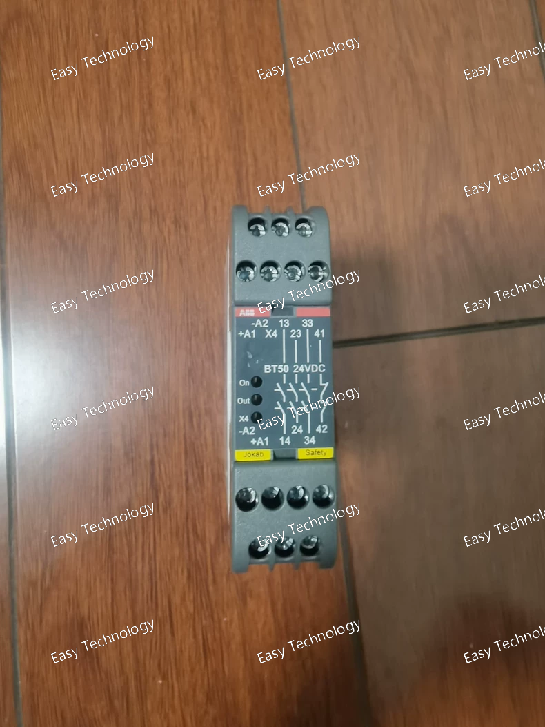
Technical Parameters Parameter / Feature Specification Model / Type BT50 24 V DC Safety Relay (2TLA010033R0000) Supply Voltage 24 V DC Output Contacts 3 × Normally‑Open (NO) + 1 × Normally‑Closed (NC) Contact Rating 6 A @ 250 V AC / 6 A @ 24 V DC Maximum Total Switching Capacity 12 A (distributed across all contacts) Minimum Switching Load 10 mA @ 10 V Contact Material Silver with gold flash (Ag + Au) Power Consumption ~1.4–1.8 W at 24 V DC Mounting / Housing 35 mm DIN‑rail; screw‑terminal connections Dimensions Width: 22.5 mm; Height: 84 mm; Depth: 120 mm Enclosure / Protection IP40 housing; IP20 terminals Operating Temperature –10 °C to +55 °C Safety Performance Safety Category 4, Performance Level e (PL e), SIL 3 Typical Applications Emergency‑stop circuits, safety interlocks, gate/door monitoring, safety output expansion, machine safety systems
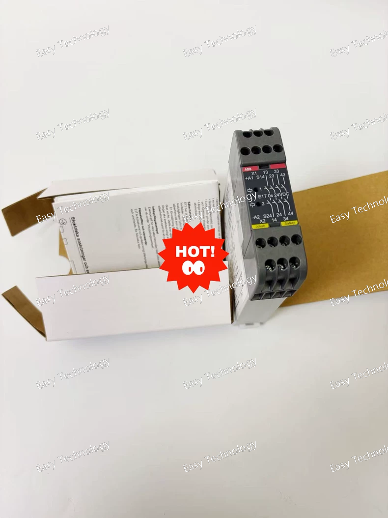
Technical Parameters Parameter / Feature Specification / Detail Series / Model E1T — Expansion Relay (Part No. 2TLA010030R0000) Supply Voltage (Us) 24 V DC Power Consumption ~ 1.5 W Output Contacts 4 × Normally‑Open (4 NO) safety‑rated relay contacts Contact Rating / Switching Capacity (Resistive Load) 6 A @ 250 V AC / 1500 VA; 6 A @ 24 V DC / 150 W Inductive Load Capacity / AC‑15 / DC‑13 2 A @ 240 V AC (AC‑15), 1 A @ 24 V DC (DC‑13) Maximum Total Switching Capacity (all contacts) 12 A (distributed across all contacts) Minimum Switching Load 10 mA @ 10 V (if contact load does not exceed 100 mA) Delay / Soft‑Stop Function Drop‑delay selectable: 0 s (this model = 0s version) Mounting / Housing / Terminals 35 mm DIN‑rail mounting; screw‑terminal / plug‑in terminal blocks Dimensions (W × H × D) 22.5 mm × 84 mm × 120 mm Protection / Enclosure Rating Enclosure: IP40; Terminal block: IP20 Isolation / Impulse Withstand Impulse withstand voltage 2.5 kV; Pollution degree 2 Operating Conditions Operating temperature: –10 °C … +55 °C; Humidity: 35–85% (non‑condensing) Safety Performance / Standards Safety Category up to Cat. 4 / Performance Level (PL) e; meets EN ISO 13849‑1 / EN 62061 / EN 954‑1 standards; SIL 3 capable Contact Material Ag + Au‑flash Typical Application / Use Case Expanding safety‑rated outputs for safety relays / controllers — for controlling multiple contactors/actuators; enabling soft‑stop of machines; increasing number of safe outputs in safety circuits
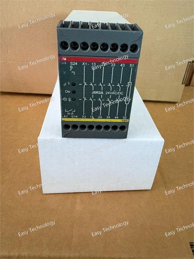
Technical Parameters Parameter / Feature Specification / Detail Product / Series JSR2A — expansion relay (Part No. 2TLA010027R0100) Supply Voltage (A1–A2) 24 V AC or 24 V DC (24 AC/DC) Output Contacts (Safety Outputs) 3 × Normally‑Open (NO) + 1 × Normally‑Closed (NC) relay contacts — total 4 contact outputs Maximum Switching Capacity per Output Up to 10 A per output contact Contact Material AgSnO₂ + Au‑flash contact material Maximum Total Switching Capacity (all contacts) Up to ~ 1840 VA (resistive AC load) when used at rated voltage; for DC loads also specified for resistive DC loads Minimum Load / Minimum Switching Capacity 10 mA @ 10 V (when contact load does not exceed 100 mA) Mounting / Installation 35 mm DIN‑rail mounting; screw‑type terminals Physical Dimensions (WxHxD) 45 mm × 74 mm × 120 mm Weight (net) ~ 0.313 kg Safety Performance / Category Suitable for expansion of safety circuits; can be used to meet Safety Category 4 / Performance Level e (when wired properly) Typical Application Expanding safety‑rated outputs from a main safety relay / controller — to drive additional contactors, actuators or devices in industrial safety systems
 TEL: Grace +86 13600179521
  Mail: info@hongkongeasy.com jilineasyyi@outlook.com
 Q Q:615739355
 ADDRESS:Unit 12, 20th Floor, Good View Commercial Centre, 2-16 Garden Street, Mong Kok, Hong Kong
 whats app


