
Industrial Controller
All product are in stock,guaranteed delivery within 3-7 days.


PRODUCT
PICTURE
BRAND
DESCRIBE
STOCK
DOWNLOAD
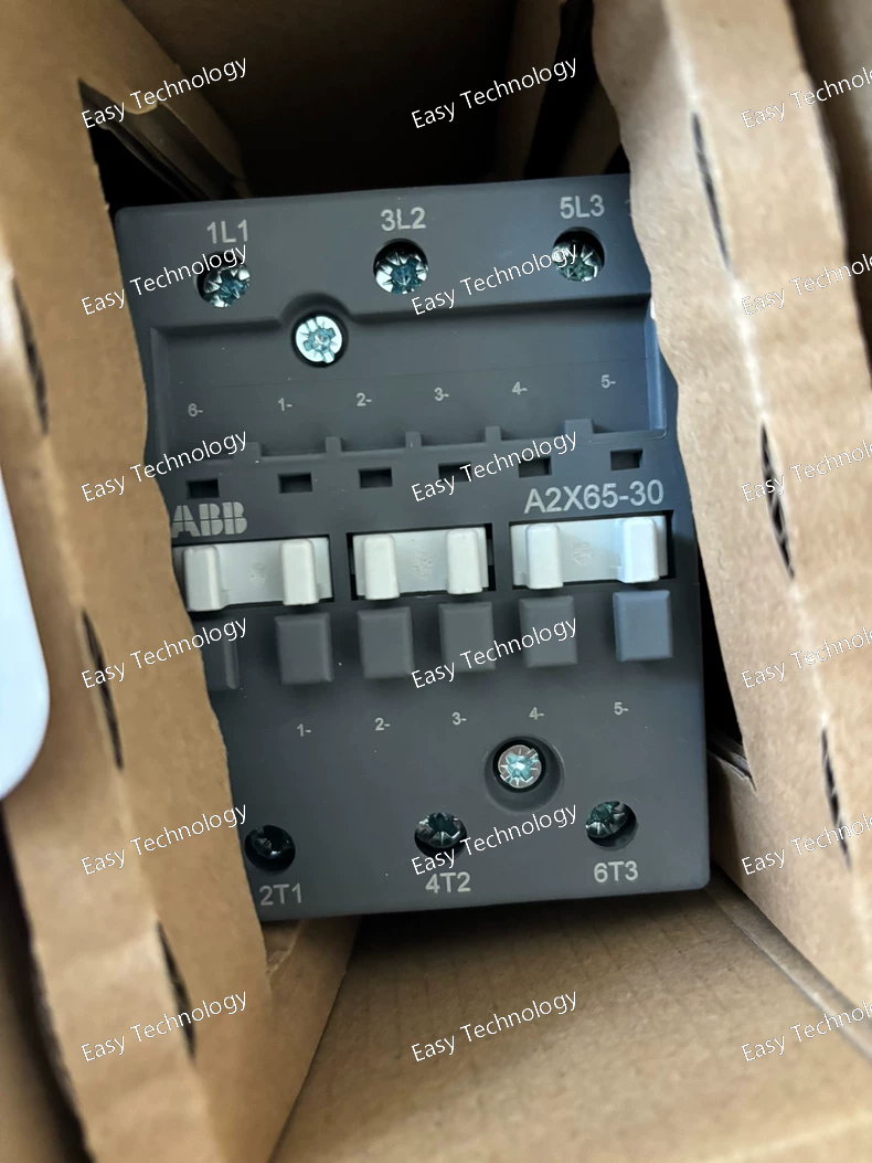
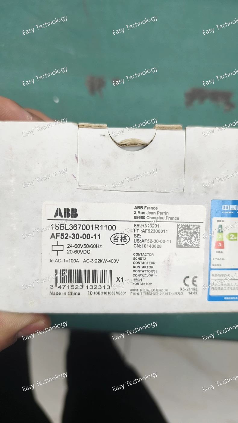
Technical Parameters Parameter Specification Product type Electromechanical contactor Product series ABB A2X series Poles 3 poles Main contact configuration 3 NO (Normally Open) Built-in auxiliary contacts 1 NO + 1 NC Rated operational voltage (Ue) Up to 690 V AC Rated operational current (Ie, AC-1) 65 A Rated motor power (AC-3) Up to 30 kW at 400 V Coil voltage 110–240 V AC / DC (variant dependent) Control voltage frequency 50 / 60 Hz Mechanical durability Up to 5 million operations Electrical durability Depends on load and utilization category Ambient operating temperature −25 °C to +55 °C Mounting Panel mounting / DIN rail with adapter Protection degree IP20 Applicable standards IEC / EN compliant Typical applications Motor starters, industrial control panels, motor control circuits
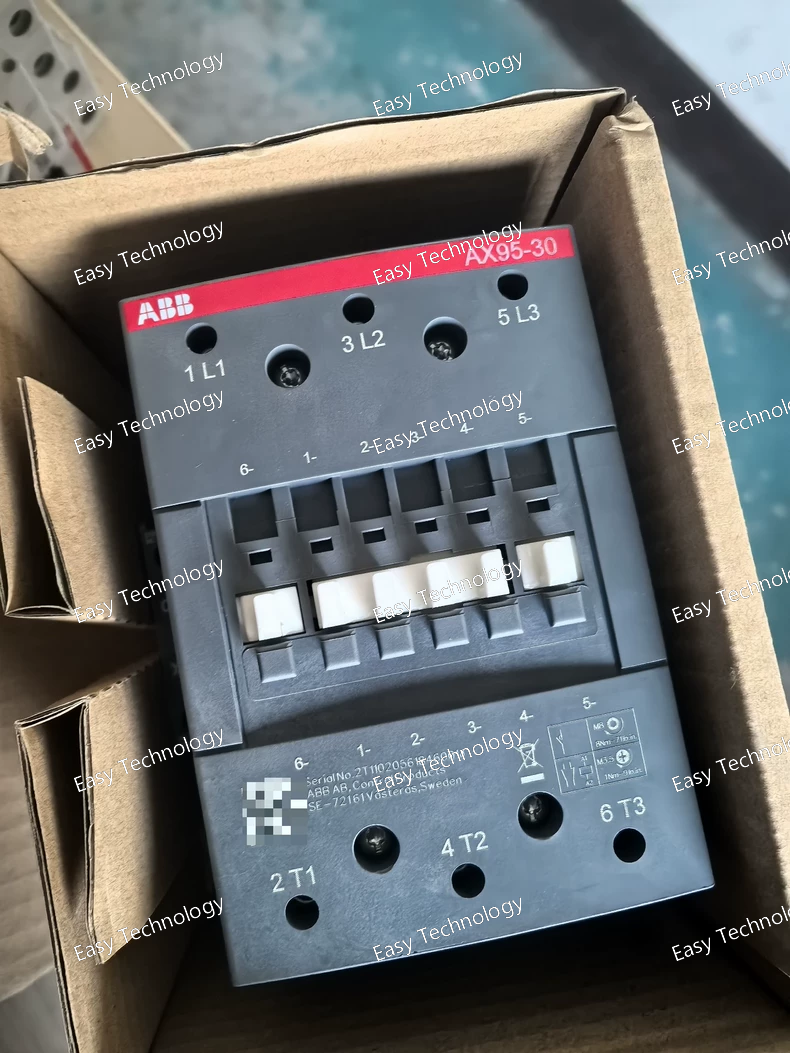
Technical Parameters Parameter Specification Product type Electromechanical contactor Product series ABB AX series Poles 3 poles Main contact configuration 3 NO (Normally Open) Built-in auxiliary contacts 1 NO + 1 NC Rated operational voltage (Ue) Up to 690 V AC Rated operational current (Ie, AC-1) Approx. 95 A Rated motor power (AC-3) Up to 45 kW at 400 V Coil voltage 100–250 V AC / DC Control voltage frequency 50 / 60 Hz Mechanical durability Up to 5 million operations Electrical durability Depends on load and utilization category Ambient operating temperature −40 °C to +70 °C Mounting Panel or DIN rail mounting Protection degree IP00 (IP20 with accessories) Applicable standards IEC / UL / CSA compliant Typical applications Motor starters, industrial control panels, power switching
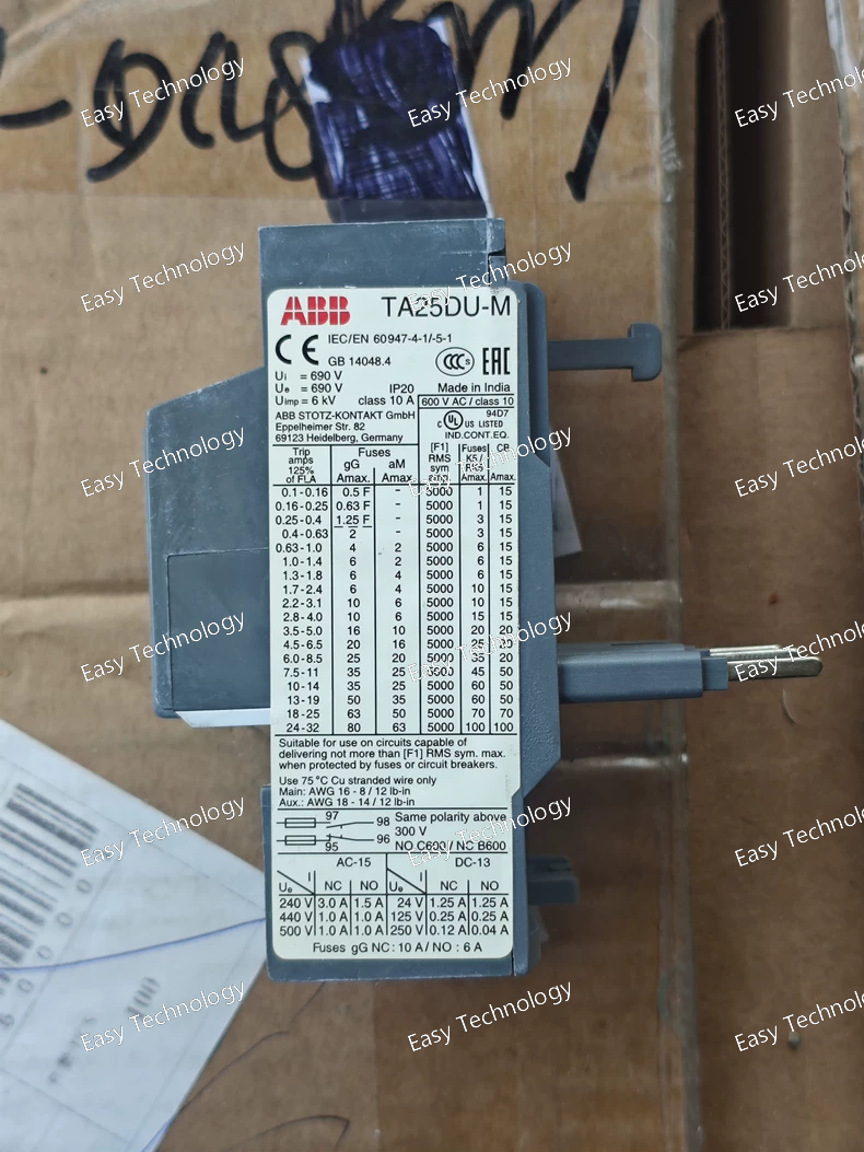
Technical Parameters Parameter Specification Product type Thermal overload relay Product series ABB TA series Compatible contactors ABB A / AF series contactors Current setting range 0.4–0.63 A Tripping class Class 10A Number of poles 3 Rated operational voltage (Ue) Up to 690 V AC Rated insulation voltage (Ui) 690 V AC Auxiliary contacts 1 NO + 1 NC (trip indication) Reset type Manual Phase failure sensitivity Yes Ambient temperature compensation Yes Mounting Direct mounting to contactor or panel mounting Protection degree IP20 Ambient operating temperature −25 °C to +55 °C Applicable standards IEC compliant Typical applications Small motor starters, control panels, industrial motor protection
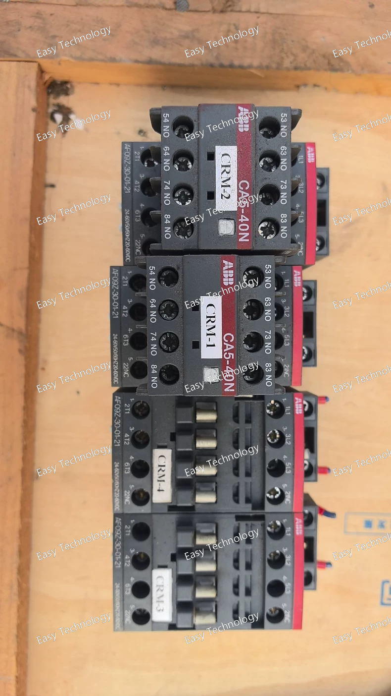
Technical Parameters Parameter Specification Product type Mini contactor Product series ABB AF series Poles 3 poles Main contact configuration 3 NO (Normally Open) Built-in auxiliary contacts 1 NO + 1 NC Rated operational voltage (Ue) Up to 400 V AC Rated operational current (Ie, AC-1) 9 A Rated motor power (AC-3) Up to 3 kW at 400 V Coil voltage 24 V / 48 V / 110 V / 230 V AC/DC (variant dependent) Control voltage frequency 50 / 60 Hz Mechanical durability Up to 10 million operations Electrical durability Depends on load and utilization category Ambient operating temperature −25 °C to +55 °C Mounting DIN rail or panel mounting Protection degree IP20 Standards IEC / EN compliant Typical applications Small motor starters, control panels, automation systems
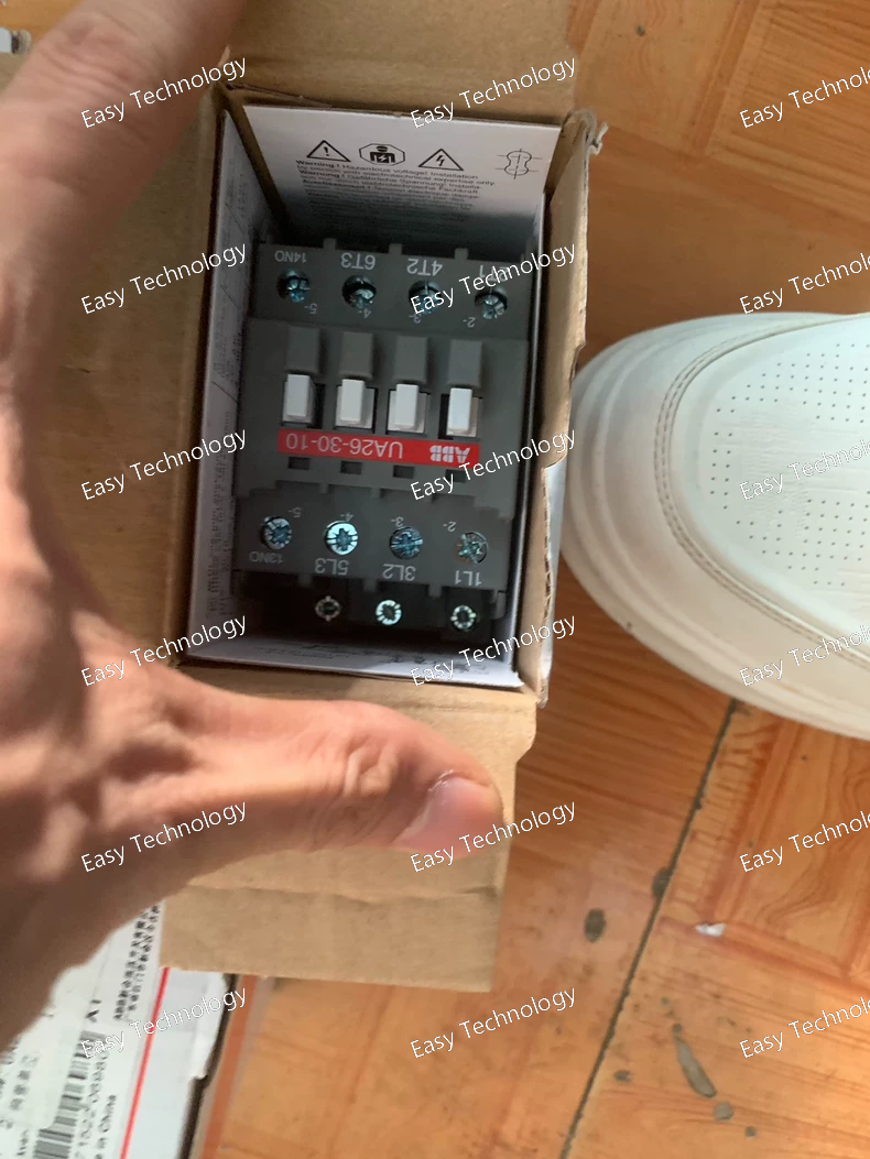
Technical Parameters Parameter Specification Product type Auxiliary contact block Product series ABB U series Poles / Contacts 2 NO + 1 NC Rated operational voltage (Ue) Up to 690 V AC Rated operational current (Ie) 10 A (AC-15), 6 A (DC-13) Mounting Direct mounting on compatible ABB contactors Mechanical durability Up to 10 million operations Electrical durability Depends on load and utilization category Control circuit compatibility Designed for ABB A / AF series contactors Operating temperature −25 °C to +55 °C Protection degree IP20 Standards IEC / EN compliant Typical applications Motor starters, control panels, auxiliary signaling circuits
Technical Parameters Parameter Specification Product type Auxiliary contact block Product series ABB AL series Poles / Contacts 1 NO + 2 NC Rated operational voltage (Ue) Up to 690 V AC Rated operational current (Ie) 10 A (AC-15), 6 A (DC-13) Mounting Snap-on / direct mounting to compatible ABB contactor Mechanical durability Up to 10 million operations Electrical durability Depends on load and utilization category Control circuit compatibility Designed to match ABB A / AF series contactors Operating temperature −25 °C to +55 °C Protection degree IP20 Standards IEC / EN compliant Typical applications Motor starters, control panels, auxiliary signaling circuits
Technical Parameters Parameter Specification Product type Thermal overload relay Product series ABB TA series Compatible contactors ABB A / AF series contactors Current setting range 52–75 A Tripping class Class 10A Number of poles 3 Rated operational voltage (Ue) Up to 690 V AC Rated insulation voltage (Ui) 690 V AC Auxiliary contacts 1 NO + 1 NC (trip indication) Reset type Manual Phase failure sensitivity Yes Ambient temperature compensation Yes Mounting Direct mounting to contactor or panel mounting Protection degree IP20 Ambient operating temperature −25 °C to +55 °C Applicable standards IEC compliant Typical applications Motor starters, MCC panels, industrial motor protection
Technical Parameters Parameter Specification Product type Softstarter Product series ABB DSM series Rated motor power 0.8 kW Rated operational voltage 200–480 V AC Supply frequency 50 / 60 Hz Rated operational current Approx. 2.5 A Motor type Three-phase asynchronous motor Starting method Voltage ramp Starting current limitation Yes Built-in bypass Yes Control voltage Control via supply voltage Control method Internal potentiometer / fixed setting Start/stop function Soft start / soft stop Ambient operating temperature −25 °C to +60 °C Mounting DIN rail or panel mounting Protection degree IP20 Typical applications Pumps, fans, conveyors, compressors
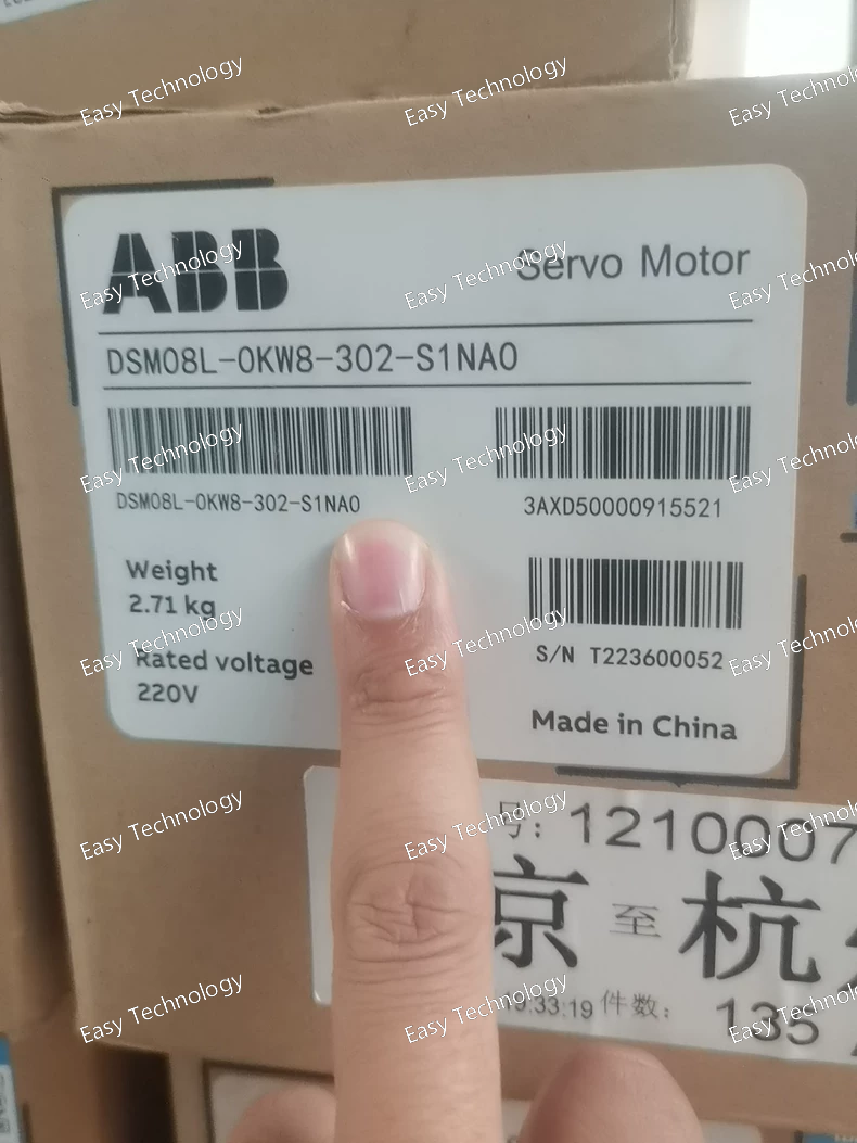
Technical Parameters Parameter Specification Product type Softstarter Product series ABB DSM series Rated motor power 0.8 kW Rated operational voltage 200–480 V AC Supply frequency 50 / 60 Hz Rated operational current Approx. 2.5 A Motor type Three-phase asynchronous motor Starting method Voltage ramp Starting current limitation Yes Built-in bypass Yes Control voltage Control via supply voltage Control method Internal potentiometer / fixed setting Start/stop function Soft start / soft stop Ambient operating temperature −25 °C to +60 °C Mounting DIN rail or panel mounting Protection degree IP20 Typical applications Pumps, fans, conveyors, compressors
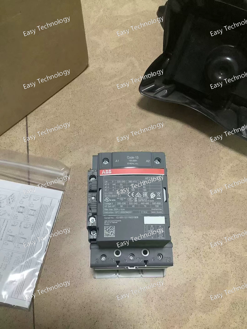
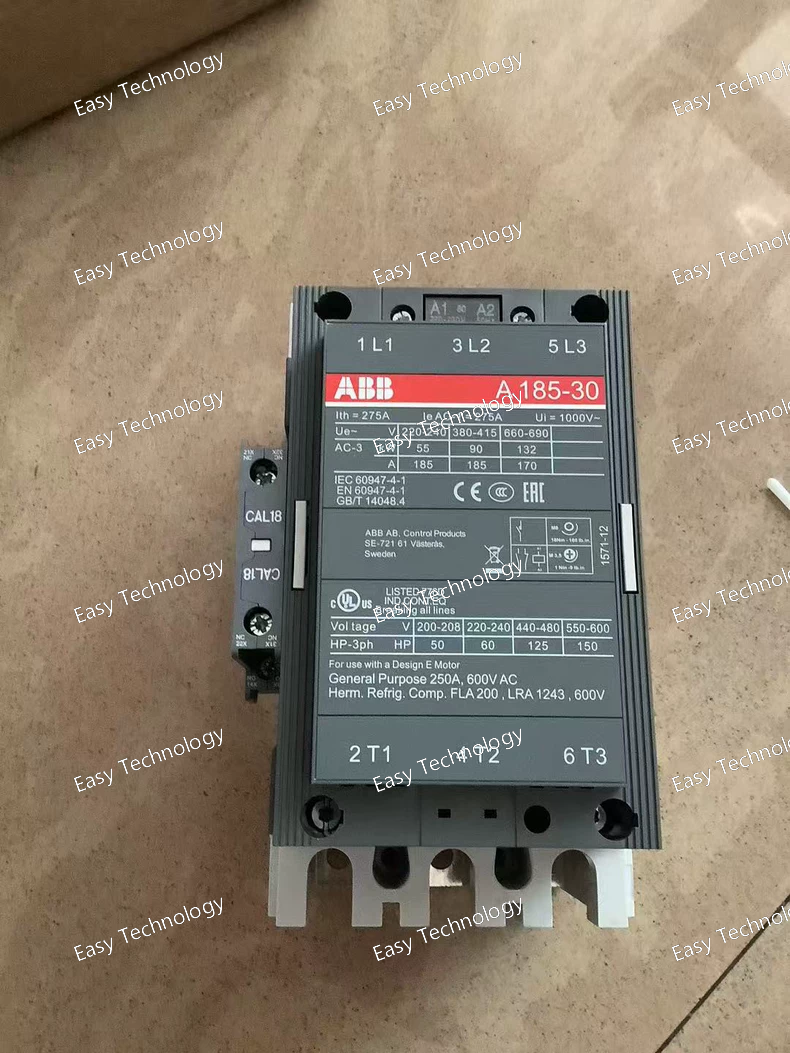
Technical Parameters Parameter Specification Product series ABB A series contactor Poles 3 poles Main contact configuration 3 NO (Normally Open) Built-in auxiliary contacts 1 NO Rated operational voltage (Ue) Up to 690 V AC Rated operational current (Ie, AC-1) Approx. 100–125 A Rated motor power (AC-3) Up to 55 kW at 400 V Utilization category AC-1, AC-3 Control circuit voltage (coil) 110 V AC (50 Hz) / 120 V AC (60 Hz) Control voltage frequency 50 / 60 Hz Mechanical durability Up to 10 million operations Electrical durability Depends on load and utilization category Ambient operating temperature −25 °C to +55 °C Mounting Panel mounting Protection degree IP00 (IP20 with accessories) Applicable standards IEC compliant Typical applications Motor starters, industrial control panels, power switching
Technical Parameters Parameter Specification Product series ABB AF series contactor Poles 3 poles Main contact configuration 3 NO (Normally Open) Built-in auxiliary contacts 1 NO + 1 NC Rated operational voltage (Ue) Up to 690 V AC Rated operational current (Ie, AC-1) Approx. 125 A Rated motor power (AC-3) Up to 37 kW at 400 V Rated motor power (UL) Approx. 60 hp at 480 V Utilization category AC-1, AC-3 Control circuit voltage (coil) 100–250 V AC / DC Control voltage frequency 50 / 60 Hz (AC) Mechanical durability Up to 10 million operations Electrical durability Depends on load and utilization category Ambient operating temperature −40 °C to +70 °C Mounting Panel mounting Protection degree IP00 (IP20 with accessories) Applicable standards IEC, UL, CSA Typical applications Motor starters, MCC panels, industrial power switching
Technical Parameters Parameter Specification Product series ABB AF series contactor Poles 3 poles Main contact configuration 3 NO (Normally Open) Built-in auxiliary contacts 1 NO + 1 NC Rated operational voltage (Ue) Up to 690 V AC Rated operational current (Ie, AC-1) Approx. 250 A Rated motor power (AC-3) Up to 110 kW at 400 V Rated motor power (UL) Approx. 150 hp at 480 V Utilization category AC-1, AC-3 Control circuit voltage (coil) 100–250 V AC / DC Control voltage frequency 50 / 60 Hz (AC) Mechanical durability Up to 5 million operations Electrical durability Depends on load and utilization category Ambient operating temperature −40 °C to +70 °C Mounting Panel mounting Protection degree IP00 (IP20 with accessories) Applicable standards IEC, UL, CSA Typical applications Motor starters, MCC panels, industrial power switching
 TEL: Grace +86 13600179521
  Mail: info@hongkongeasy.com jilineasyyi@outlook.com
 Q Q:615739355
 ADDRESS:Unit 12, 20th Floor, Good View Commercial Centre, 2-16 Garden Street, Mong Kok, Hong Kong
 whats app


