
Industrial Controller
All product are in stock,guaranteed delivery within 3-7 days.


PRODUCT
PICTURE
BRAND
DESCRIBE
STOCK
DOWNLOAD
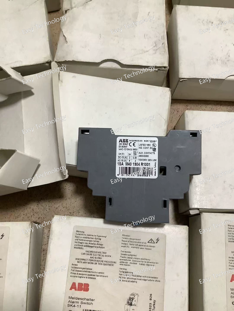
Technical Specifications Parameter Specification Part Number / Model 1SAM401904R1001 ABB Type / Code SK4‑11 Signal Contact Product Type Auxiliary signal contact block Contact Configuration 1 NO + 1 NC Rated Operational Voltage Up to 690 V AC Rated Insulation Voltage (Ui) 690 V Rated Current – AC‑15 ~6 A @ 24 V AC / ~4 A @ 230 V AC / ~3 A @ 400 V AC Rated Current – DC‑13 ~1 A @ 24 V DC / ~0.5 A @ 110 V DC / ~0.25 A @ 220 V DC Conventional Free‑Air Thermal Current (Ith) 10 A Degree of Protection IP20 Connecting Capacity Flexible/ferrule: 0.5–2.5 mm²; Rigid: 0.5–2.5 mm² Tightening Torque 0.8–1.2 N·m Wire Stripping Length 10 mm Mounting Style Side‑mount auxiliary contact block for manual starters Ambient Temperature (Operation) –25 °C … +70 °C Standards Compliance IEC/EN 60947‑1, IEC/EN 60947‑4‑1, IEC/EN 60947‑5‑1; UL 508; CSA 22.2 No. 14 Weight (Approx.) 0.093 kg Dimensions 18 mm (W) × 89 mm (H) × 69 mm (D)
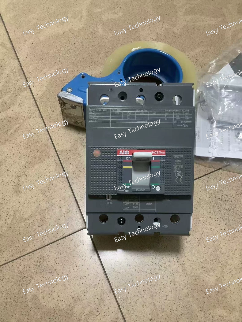
Technical Specifications Parameter Specification Part / Model ABB 1SDA068059R1 Product Type Molded Case Circuit Breaker (MCCB) Series / Family Tmax XT3N Trip Unit / Release Thermo‑magnetic (TMD), adjustable Number of Poles 3‑pole (3P) Frame / Uninterrupted Current (Iu) 250 A Thermo‑magnetic Setting Range 175 … 250 A (adjustable) Rated Operational Voltage (Ue) 690 V AC / 500 V DC Rated Insulation Voltage (Ui) ~800 V Rated Impulse Withstand Voltage (Uimp) 8 kV Rated Ultimate Breaking Capacity (Icu) • 220‑240 V AC 50 kA • 380‑415 V AC 36 kA • 440 V AC ~25 kA • 500 V AC ~20 kA • 690 V AC ~5 kA Rated Service Breaking Capacity (Ics) Similar to Icu per voltage level Rated Instantaneous Short‑Circuit Setting (Ii) ~2500 A **AC/DC Rated Yes (AC & DC operation)** Terminal Connection Front bolt terminals Terminal Torque ~8 N·m Connection Capacity Main circuit busbars/cables Mechanical Durability ~25,000 operations Electrical Durability ~8,000 operations Standards Compliance IEC 60947‑2 Degree of Protection IP20 Typical Weight ~1.6–1.7 kg Dimensions (approx.) ~105 mm wide × ~150 mm high × ~70 mm deep
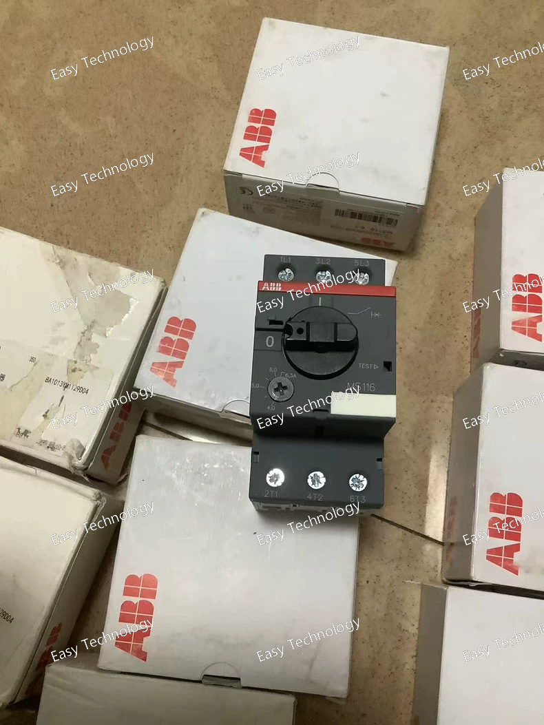
Technical Specifications Parameter Specification Part / Model 1SAM250000R1009 (MS116‑6.3) Product Type Manual Motor Starter / Motor Protection Circuit Breaker Rated Operational Current (Ie) 6.3 A Adjustment / Setting Range 4.0 – 6.3 A Number of Poles 3 poles (3P) Rated Operational Voltage (Ue) up to 690 V AC Rated Insulation Voltage (Ui) 690 V Rated Impulse Withstand Voltage (Uimp) 6 kV Trip Class 10 A (thermal) Instantaneous Trip Setting (Ii) ~78.8 A Rated Service Breaking Capacity (Ics) 50 kA @ 230/400 V AC; 6 kA @ 440 / 500 V AC; 2 kA @ 690 V AC Rated Ultimate Breaking Capacity (Icu) 75 kA @ 230/400 V AC; 18 kA @ 440 V AC; 15 kA @ 500 V AC; 3 kA @ 690 V AC Rated Power (AC‑3) ~2.2 kW (400 V AC, 3‑phase) Mounting DIN‑rail (TH35) or panel Terminal Type Screw terminals Handle / Control Rotary ON/OFF handle with position indication Degree of Protection IP20 (housing) Pollution Degree 3 Ambient Temperature (Operation) –25 °C to +70 °C (operating) Ambient Temperature (Compensated) –25 °C to +55 °C Mechanical Durability ~100,000 cycles Electrical Durability ~100,000 operations Weight ~0.26 kg Dimensions (approx.) Width ~45 mm × Height ~90 mm × Depth ~85.6 mm
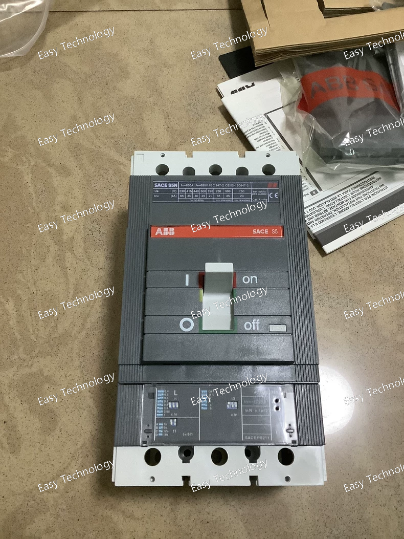
Technical Specifications Parameter Specification Part Number / Model 1SDA038675R1 Product Type Molded Case Circuit Breaker (MCCB) Series / Family ABB SACE Isomax S5N Trip Unit / Release Electronic PR211 (LI or similar) Number of Poles 3‑pole (3P) Rated Current (In) 630 A Frame / Uninterrupted Current (Iu) ~630 A Application Industrial low‑voltage AC distribution Rated Operational Voltage (Ue) Up to 690 V AC (typical for low‑voltage MCCBs) Rated Insulation Voltage (Ui) 1000 V AC (typical for this class) Rated Impulse Withstand Voltage (Uimp) 8 kV Short‑Circuit Breaking Capacity (Icu) High interrupting capability across common system voltages (manufacturer spec varies by unit and release type) Service Breaking Capacity (Ics) Similar to Icu depending on voltage and release settings Trip Settings / Functions Adjustable electronic protection (long‑time, short‑time/instantaneous functions) via PR211 unit Mounting Type Fixed installation with front terminals Standards Compliance IEC/EN 60947‑2 (typical for MCCBs) Typical Use Main breaker, feeder protection, motor protection coordination Weight & Dimensions Hefty industrial breaker (weight and size typical for 630 A class breakers)
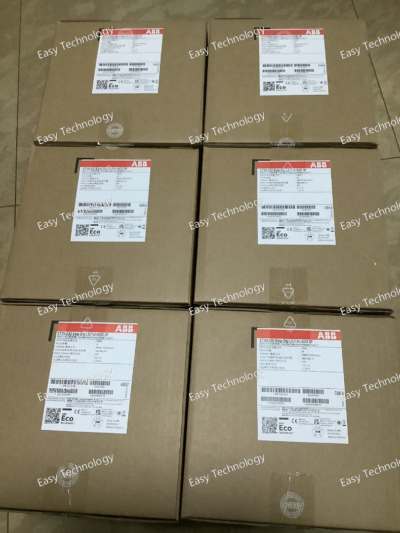
Technical Specifications Parameter Specification Part Number / Model 1SDA100355R1 Product Molded Case Circuit Breaker (MCCB), Tmax XT5N series Trip Unit EKIP DIP LS/I electronic release Number of Poles 3‑pole (3P) Rated Current (In) 630 A Rated Operational Voltage (Ue) 690 V AC Rated Insulation Voltage (Ui) 1000 V Rated Impulse Withstand Voltage (Uimp) 8 kV Interrupting Capacity – Icu 70 kA @ 220‑240 V AC / 36 kA @ 380‑440 V AC / 25 kA @ 500 V AC / 20 kA @ 690 V AC Service Breaking Capacity – Ics Same as Icu (varies by voltage) Frame Size XT5N 630 Connection Type Front bolt terminals Mounting Type Fixed installation Standards Compliance IEC 60947‑2 Rated Power Loss ~45 W (typical) Mechanical Endurance ~20,000 operations Electrical Endurance ~5,000 electrical cycles Typical Dimensions Width ~140 mm, Height ~205 mm, Depth ~103.5 mm Approx. Weight ~4.8 kg
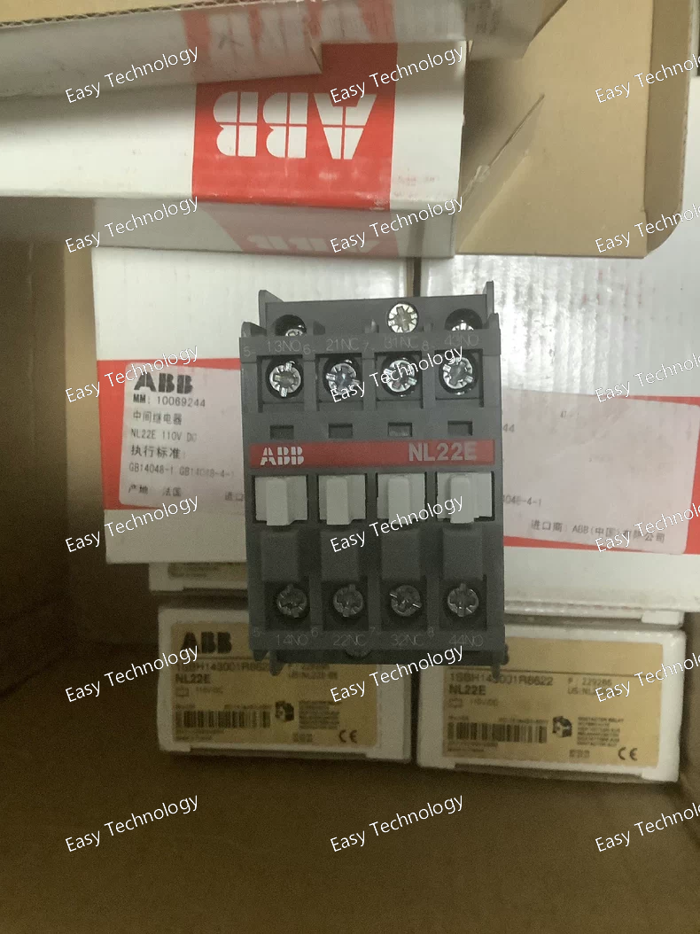
Technical Specifications Parameter Specification Product / Model ABB NL22E DC110V Type Control / Auxiliary Contactor / Relay Coil Voltage 110 V DC Contact Configuration Varies by specific sub‑model (commonly multi‑pole auxiliary contacts such as 2 NO + 2 NC) Rated Control Voltage 110 V DC Actuation Type Electromagnetic DC coil operated Usage Control and switching of auxiliary circuits, ladder logic, PLC outputs, interposing relay functions Mounting Panel / DIN‑rail compatible mount (depending on accessory base) Terminal Type Screw or plug‑in terminals (model dependent) Typical Applications Auxiliary control, interlocking, motor starter control logic Compliance / Standards IEC/EN electrical control switchgear standards (exact certifications depend on specific variant)
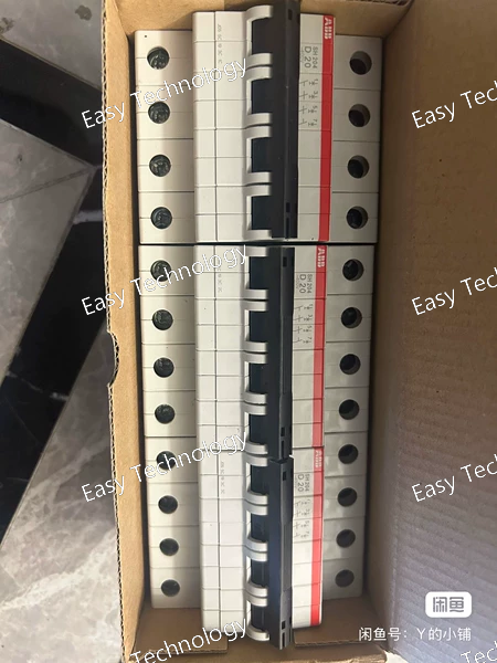
Technical Specifications Parameter Specification Model / Type ABB S204‑D63 Product Type 4‑Pole Miniature Circuit Breaker (MCB) Series / Family System pro M / S200 series Tripping Characteristic Type D (high inrush tolerance) Rated Current (In) 63 A Number of Poles 4 poles (4P) Rated Operational Voltage (Ue) 400 V AC (IEC 60898‑1) / 440 V AC (IEC 60947‑2) Rated Insulation Voltage (Ui) 440 V AC Rated Impulse Withstand Voltage (Uimp) 4 kV (higher at sea level) Rated Frequency 50 / 60 Hz Rated Ultimate Breaking Capacity (Icu) 20 kA @ 230 V AC; 10 kA @ 400 V AC Rated Service Breaking Capacity (Ics) 15 kA @ 230 V AC; 7.5 kA @ 400 V AC Rated Short‑Circuit Capacity (Icn) 6 kA (AC) Energy Limiting Class Class 3 Connection Type Failsafe bi‑directional screw terminals Tightening Torque ~2.8 N·m Mounting DIN‑rail (TH35) Contact Position Indication Red ON / Green OFF Pollution Degree 3 Overvoltage Category III Degree of Protection IP20 Ambient Operating Temperature –25 °C to +55 °C Connectable Conductors Solid: 0.75–35 mm²; Flexible: 0.75–25 mm² Mechanical Endurance ~20,000 cycles Electrical Endurance ~10,000 AC cycles
Technical Specifications Parameter Specification Part / Model ABB S204‑D50 Product Type 4‑Pole Miniature Circuit Breaker (MCB) Series / Family System pro M / S200M Tripping Characteristic Type D (high inrush tolerance) Rated Current (In) 50 A Rated Operational Voltage (Ue) 400 V AC (IEC 60898‑1) / 440 V AC (IEC 60947‑2) Rated Insulation Voltage (Ui) 440 V AC Rated Impulse Withstand Voltage (Uimp) 4 kV Rated Frequency 50 / 60 Hz Rated Short‑Circuit Breaking Capacity (Icn) 6 kA at 400 V AC Rated Ultimate Breaking Capacity (Icu) ~10 kA at 400 V AC Rated Service Breaking Capacity (Ics) ~7.5 kA at 400 V AC Energy Limiting Class Class 3 Pollution Degree 3 Overvoltage Category III Connection Type Screw terminals (failsafe bi‑directional) Mounting DIN‑rail (TH35) Contact Position Indication Red ON / Green OFF Ambient Operating Temperature –25 °C to +55 °C Degree of Protection IP20 Number of Poles 4 poles Width in Modular Units 4 modules Connectable Conductors Solid: 0.75 – 35 mm²; Flexible: 0.75 – 25 mm² Standards Compliance IEC/EN 60898‑1, IEC/EN 60947‑2, UL 1077
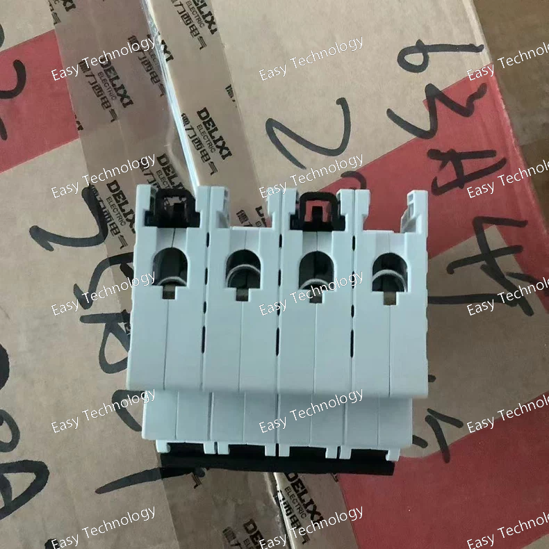
Technical Specifications Parameter Specification Product / Model ABB S204‑D40 Product Type Miniature Circuit Breaker (MCB) Series / Family System pro M / S200 Number of Poles 4 poles (4P) Rated Current (In) 40 A Tripping Characteristic Type D (high inrush tolerance) Rated Operational Voltage (Ue) 400 V AC (IEC 60898‑1), 440 V AC (IEC 60947‑2) Rated Insulation Voltage (Ui) 440 V AC Rated Impulse Withstand Voltage (Uimp) 4 kV Rated Frequency 50 / 60 Hz Rated Ultimate Breaking Capacity (Icu) 20 kA @ 230 V AC; 10 kA @ 400 V AC Rated Service Breaking Capacity (Ics) 15 kA @ 230 V AC; 7.5 kA @ 400 V AC Rated Short‑Circuit Current (Icn) 6 kA AC Energy Limiting Class 3 Overvoltage Category III Pollution Degree 3 Connection Type Screw terminals (failsafe bi‑directional) Tightening Torque 2.8 N·m Mounting DIN‑rail (TH35) Contact Position Indication Red ON / Green OFF Ambient Operating Temperature –25 °C to +55 °C Typical Dimensions (W×H×D) ~70 mm × 88 mm × 69 mm Weight (approx.) ~0.5 kg
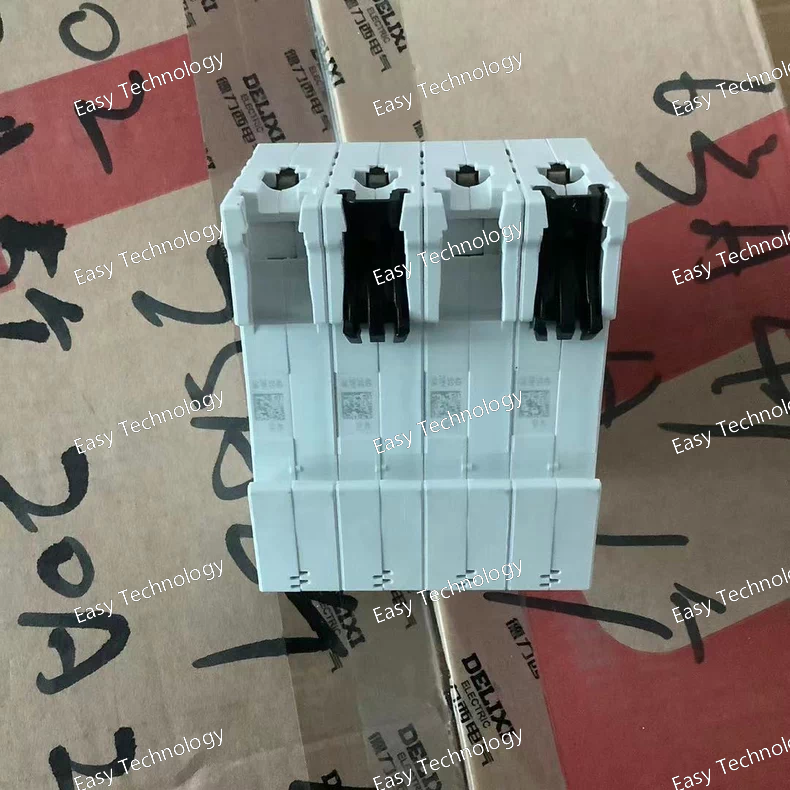
Technical Specifications Parameter Specification Part / Model S204‑D25 Product Type Miniature Circuit Breaker (MCB) Series / Family System pro M / S200 series Number of Poles 4 poles (4P) Tripping Characteristic D‑curve Rated Current (In) 25 A Rated Operational Voltage up to 400 V AC (IEC 60898‑1) / 440 V AC (IEC 60947‑2) Rated Insulation Voltage (Ui) 440 V AC Rated Impulse Withstand Voltage (Uimp) 4 kV (typically ~6.2 kV at sea level) Rated Short‑Circuit Capacity (Icn) 6 kA (AC) Rated Ultimate Breaking Capacity (Icu) up to 10 kA (depending on voltage level) Rated Service Breaking Capacity (Ics) ~7.5 kA (typical at 400 V AC) Frequency 50 / 60 Hz Connection Type Screw terminals (bi‑directional cylinder‑lift) Mounting DIN‑rail (TH35) Contact Position Indication Red ON / Green OFF Pollution Degree 3 Overvoltage Category III Energy Limiting Class 3 Electrical Endurance ~20,000 AC cycles Mechanical Endurance ~20,000 cycles Terminal Torque ~2.8 N·m Operational Temperature Range –25 °C to +55 °C Dimensions (approx.) Width ~70 mm × Depth ~69 mm × Height ~88 mm Weight (approx.) ~0.5 kg
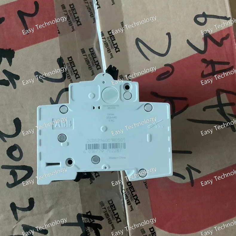
Technical Specifications Parameter Specification Part / Model S204‑D20 Product Type Miniature Circuit Breaker (MCB) Number of Poles 4 poles (4P) Tripping Characteristic Type D (high inrush tolerance) Rated Current (In) 20 A Rated Operational Voltage (Ue) Up to 400 V AC (IEC 60898‑1) / 440 V AC (IEC 60947‑2) Rated Insulation Voltage (Ui) 440 V AC Rated Impulse Withstand Voltage (Uimp) 4 kV Frequency 50 / 60 Hz Rated Short‑Circuit Capacity (Icn) 6 kA (AC) Rated Ultimate Short‑Circuit Breaking Capacity (Icu) ~10 kA (AC) Rated Service Short‑Circuit Breaking Capacity (Ics) ~7.5 kA (AC) Energy Limiting Class Class 3 Connection Type Screw terminals Mounting DIN rail (TH35) Terminal Torque ~2.8 N·m Degree of Protection IP20 Pollution Degree 3 Overvoltage Category III Ambient Operating Temperature –25 °C to +55 °C Standards Compliance IEC/EN 60898‑1; IEC/EN 60947‑2; UL 1077; CSA Contact Position Indication Red ON / Green OFF Typical Dimensions ~70 mm width × 69 mm depth × ~88 mm height Typical Weight ~0.5 kg
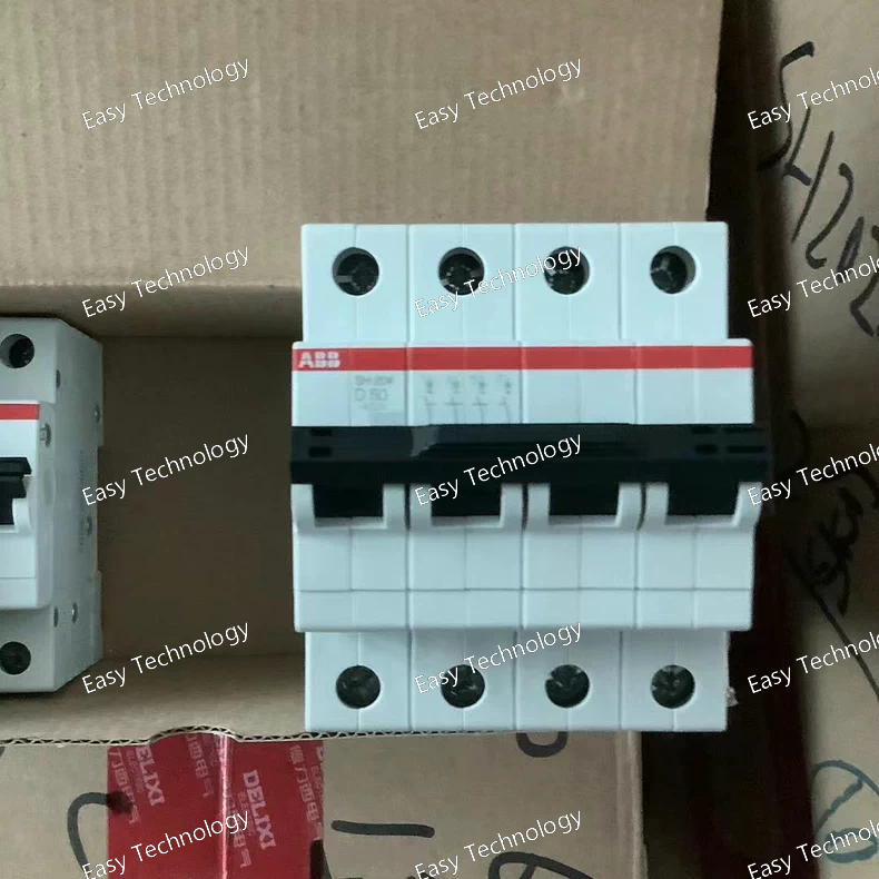
Technical Specifications Parameter Specification Part / Model S204‑D16 (ABB) Product Type Miniature Circuit Breaker (MCB) Number of Poles 4 poles (4P) Rated Current (In) 16 A Trip Characteristic Type D (high inrush tolerance) Rated Operational Voltage up to 440 V AC (IEC) / 277 V AC (UL) Rated Insulation Voltage (Ui) ~440 V Rated Impulse Withstand Voltage (Uimp) ~4 kV Rated Short‑Circuit Breaking Capacity (Icn) 6 kA AC Rated Ultimate Breaking Capacity (Icu) up to 10 kA AC Rated Service Breaking Capacity (Ics) ~7.5 kA (typical) Frequency 50 / 60 Hz Connection Type Screw terminals Mounting DIN‑rail TH35 Actuator / Toggle Sealable ON/OFF marking Contact Position Indication Red ON / Green OFF Electrical Endurance ~20,000 AC cycles Mechanical Endurance ~20,000 cycles Overvoltage Category III Pollution Degree 3 Degree of Protection IP20 Ambient Temperature Range −25 °C to +55 °C Connectable Conductors Rigid & flexible up to ~35 mm² Standards Compliance IEC/EN 60898‑1; IEC/EN 60947‑2; UL 1077; CSA
 TEL: Grace +86 13600179521
  Mail: info@hongkongeasy.com jilineasyyi@outlook.com
 Q Q:615739355
 ADDRESS:Unit 12, 20th Floor, Good View Commercial Centre, 2-16 Garden Street, Mong Kok, Hong Kong
 whats app


