
Industrial Controller
All product are in stock,guaranteed delivery within 3-7 days.


PRODUCT
PICTURE
BRAND
DESCRIBE
STOCK
DOWNLOAD
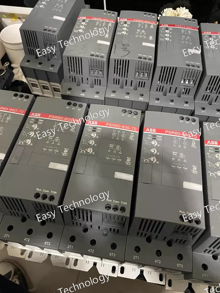
Parameter Value / Description Explanation Series / Range PSR (Programmable Safety Relay) ABB's comprehensive family of modular safety relays. Product Type Safety Relay Module (Function Module) Provides specific safety logic. Requires a base unit and power supply. Model Number PSR60-600-70 Code Breakdown: - PSR60: Series designation (PSR) and base unit compatibility (60mm wide). - 600: Indicates a dual-channel safety function module with cross-circuit monitoring. - 70: Specific variant, often denotes a 2-channel module with manual start (S33-S34). Safety Function Two-hand control, EMERGENCY STOP, Safety gate monitoring Monitors two independent signal paths. Requires complementary (N/O and N/C) contacts from each safety device for cross-fault detection. Safety Integrity • Safety Category: 4 (EN 954-1) • Performance Level (PL): PL e (EN ISO 13849-1) • Safety Integrity Level (SIL): SIL 3 (EN/IEC 62061) Meets the highest levels of safety for machinery control systems. Supply Voltage 24V DC (via the base unit) Standard voltage for industrial control circuits. Number of Channels 2 (Dual Channel) Can monitor two independent safety inputs (e.g., two contacts from a safety gate). Input Type Cross-circuit monitoring Requires both a Normally Open (NO) and a Normally Closed (NC) contact from each safety device to detect contact welding or faults. Outputs • Safety Outputs: 2 or 3 semiconductor safety outputs (OSSDs - Output Signal Switching Devices), typically via the base unit. • Auxiliary Outputs: At least one signaling contact for fault or status indication. Safety outputs are force-guided (mechanically linked) relays to ensure safe switching. Start Function Manual Start (with monitored start option) After a safety trip, the circuit requires a deliberate manual reset (via a separate reset button) to restart. The start circuit itself can be monitored. Time Delay Typically not applicable for this basic function module. Other PSR modules offer timed functions. Dimensions (Module) Approx. 22.5mm wide (single module) Designed to be snapped onto a DIN rail-mounted base unit (e.g., PSR-TB60). Connection Spring-cage or screw terminal (via base unit) Standards Compliance EN 60204-1, EN 954-1, EN ISO 13849-1, EN/IEC 62061, UL 508, CSA C22.2 Complies with international machinery safety and control standards. Ambient Temperature -25°C to +55°C (operation) Standard industrial operating range.
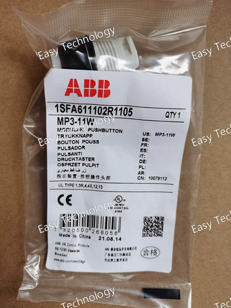
Parameter Value / Description Explanation Series / Range MetaPRO ABB's advanced series for distribution board instrumentation and measurement. Product Type Intelligent Incoming Line Measurement & Protection Unit Combines metering, monitoring, and protection in one device. Model Number MP3-11W Code Breakdown: - MP3: MetaPRO series, 3-phase. - 1: Standard frame size / variant. - 1: Specific function set (indicating basic measurement/protection). - W: Built-in high-precision energy metering (kWh, kVArh). System Type 3-Phase, 4-Wire (3P4W) Designed for systems with three phases and a neutral. Measurement Inputs • 3 Current (via CTs) • 4 Voltage (3Ph-N) Direct connection to voltage; current measured via external Current Transformers (CTs). Rated Voltage (U<sub>n</sub>) 3 x 57.7/100V, 3 x 230/400V AC Standard measurement voltages. Must match PT outputs or system voltage directly. Rated Current (I<sub>n</sub>) 1A or 5A (via CTs) Depends on the connected Current Transformers. Measurement Accuracy • Energy (Active/Reactive): Class 0.5S (per IEC 62053-22) • Voltage/Current/Power: Typically ±0.5% The “0.5S class” is a high-accuracy standard suitable for billing purposes. Core Functions Measurement: • All electrical parameters (V, I, kW, kVA, kVAr, PF, Hz) • Energy import/export (kWh, kVArh) • Demand (MD) • Power quality (THD, unbalance) Protection: • Over/Under Voltage • Over/Under Frequency • Over Current (basic) Provides a complete dashboard of system health and consumption. Communication • RS485 serial communication (standard) • Protocols: Modbus RTU Allows integration into SCADA, BMS, or ABB’s own energy management systems. Power Supply Auxiliary supply: Typically 24-240V AC/DC (wide range) Powers the internal electronics independently. Display Multi-line LCD Display Local readout of all measured values, energy totals, and status. Mounting Panel Mounting Designed for cut-out mounting on a switchboard door or panel. Standards Compliance IEC 61557-12 (Electrical safety), IEC 62053-22 (Metering accuracy), IEC 61010-1 (Safety)
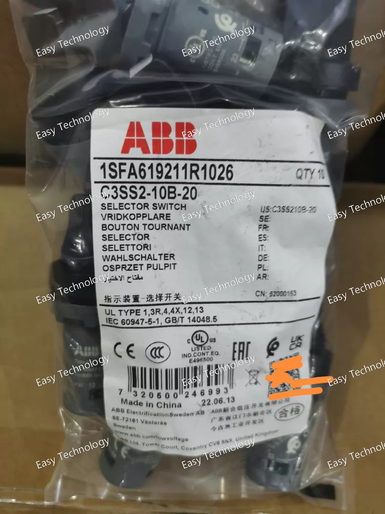
Technical Specifications Parameter Value / Description Explanation Series / Range System Pro M compact ABB's mainstream, compact distribution equipment series. Product Type Miniature Circuit Breaker (MCB) Core function: Protection against overload and short circuit. Model Breakdown C3SS2-10B-20 Code Decoded: - C3: Product family/design platform. - SS2: "S" for MCB, "S2" indicates a 2-pole device. - 10: Breaking Capacity = 10 kA (I<sub>cn</sub>). - B: Tripping Characteristic = Type B. - 20: Rated Current = 20 Amperes. Number of Poles 2 Poles (1+N) "1" = Fully protected phase pole. "N" = Neutral pole (primarily for isolation). Rated Current (I<sub>n</sub>) 20 A The continuous current the device is designed to carry. Rated Voltage (U<sub>e</sub>) 230/400V AC Suitable for single-phase (230V) and three-phase (400V) systems. Tripping Characteristic Type B Trips between 3x and 5x I<sub>n</sub> (60A to 100A). For general use: lighting, sockets, residential circuits. Breaking Capacity (I<sub>cn</sub>) 10 kA Maximum short-circuit current it can safely interrupt at rated voltage. Insulation Voltage (U<sub>i</sub>) 500V Rated insulation voltage. Impulse Withstand Voltage (U<sub>imp</sub>) 4 kV Resistance to voltage surges (e.g., from lightning). Pollution Degree 2 For normal indoor environments. Mounting DIN Rail Mounting Standard 35mm top-hat (TS35) DIN rail. Standards Compliance IEC/EN 60898-1 IEC/EN 60947-2 International and European standards for circuit-breakers. Terminals Screw Clamp Terminals Suitable for rigid and flexible conductors (check local guidelines for torque). Electrical Life Typically >10,000 cycles Mechanical and electrical endurance. Ambient Temperature -25°C to +55°C (for calibration) Operating temperature range. Storage Temperature -40°C to +70°C Approximated Dimensions (W x H x D) ~36mm x 78mm x 70mm 2-module width on a DIN rail.
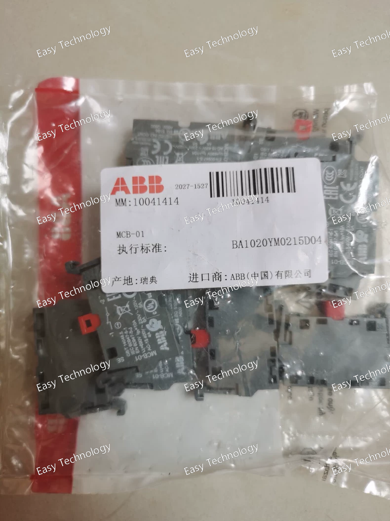
Key Parameters Category Parameter Specification / Description General Model ABBMCB-01 Compatible Breakers ABB Emax 2 series air circuit breakers (ACBs) Primary Function Communication interface for monitoring and control Electrical Supply Voltage Typically powered directly from the breaker (auxiliary voltage), e.g., 24-250 V AC/DC. (Must be verified with the official datasheet for the specific version.) Power Consumption Low power, sourced from the breaker's auxiliary supply. Communication Primary Protocol Modbus RTU Physical Interface RS-485 (2-wire, half-duplex) Address Range Configurable Modbus slave address (typically 1-247) Baud Rate Configurable (e.g., 9600, 19200, 38400, 57600, 115200 bps) Parity Configurable (None, Even, Odd) Data & Functions Monitored Parameters Current (IL1, IL2, IL3, IN), Voltage (VLN, VLL), Power (kW, kVAR, kVA), Energy (kWh, kVARh), Frequency, Power Factor, etc. Status Information Breaker position (Open/Closed), Spring charging state, Ready to Close, Alarm/Trip status. Control Commands Remote OPEN, REMOTE CLOSE (subject to interlock and authorization). Protection Data Read (and sometimes set) protection thresholds, view trip logs and event history. Alarms System warnings, pre-alarms, and trip alarms. Mechanical & Environmental Mounting Direct plug-in or fixed mounting on the Emax 2 breaker. Operating Temperature -25°C to +70°C (typical for industrial environments) Standards & Approvals Complies with relevant IEC/EN standards for industrial equipment.
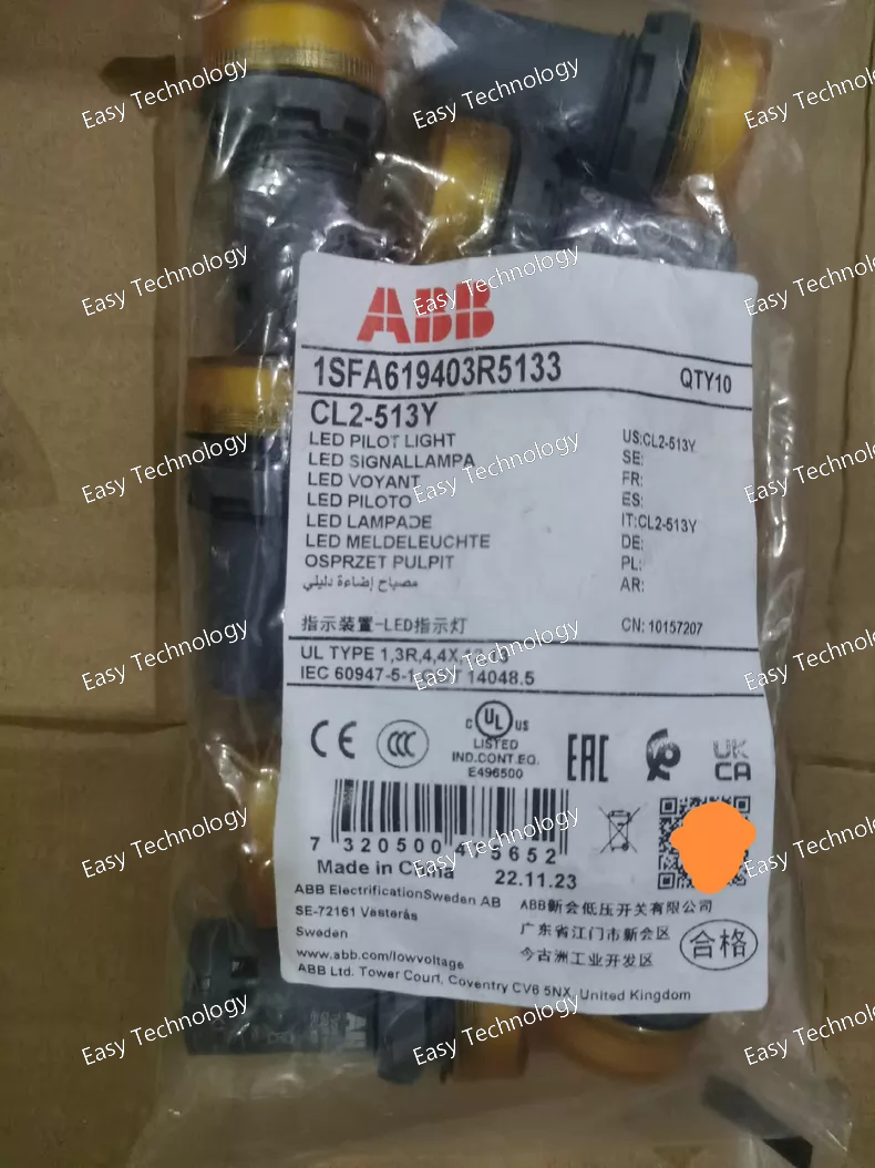
Key Parameters Parameter Specification Model / Part Number CL2‑513Y (ABB) ABB Ordering Code 1SFA619403R5133 Product Type Compact Illuminated Pilot Light Indicator Color Yellow Light Source Integrated LED (no separate bulb) Rated Operational Voltage 110 – 130 V AC Rated Frequency 50 / 60 Hz Rated Current ~15–17 mA at 110–130 V AC Mounting Hole Diameter 22 mm standard panel cut‑out Degree of Protection (Front) IP66 / IP67 / IP69K Degree of Protection (Terminals) IP20 Connection Type Screw clamp terminals Terminal Torque ~0.9 N·m Wire Stripping Length ~8 mm Ambient Operating Temperature –25 °C to +70 °C Storage Temperature –40 °C to +85 °C Pollution Degree 3 Body Color / Housing Gray/black body with yellow lens Net Weight ~0.018 kg
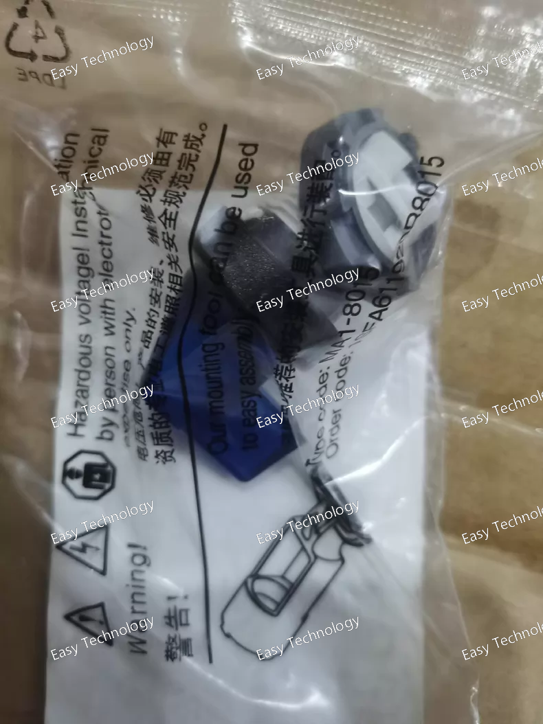
Key Parameters Parameter Specification Model / Part Number M2SS4‑11L (ABB) Catalog / Ordering Code 1SFA611203R1104 Product Type Modular Illuminated Selector Switch Actuator Color Blue Number of Positions 2 Positions (Maintained) Handle Style Long handle (rotary) Illumination Illuminated (LED ready, requires LED block) Contact Blocks Not included (modular design) Mounting Cut‑out 22 mm panel hole Bezel Material Black plastic Operator Function Maintained (latching) Protection Degree (Front) High ingress protection (e.g., IP66/67/69K) typical for modular pilot devices Mechanical Durability Designed for high mechanical reliability Ambient Operating Temperature –25 °C to +70 °C typical Storage Temperature –40 °C to +85 °C typical Usage Manual selector for control logic, mode selection, and operator input
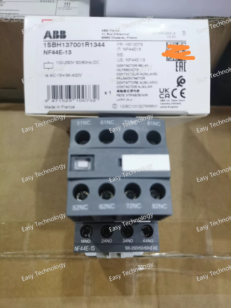
Key Parameters Parameter Specification Model / Part Number NF44E‑13 Product Type Contactor relay / control relay Number of Poles 8 poles Contact Configuration 4 × Normally Open (4 NO) + 4 × Normally Closed (4 NC) Coil / Control Voltage 100 – 250 V AC or DC Rated Operational Voltage (Auxiliary) Up to ~690 V AC for auxiliary circuits Rated Operational Current (AC‑15) 6 A @ 24 – 127 VAC; 4 A @ 220 – 240 VAC; 3 A @ 400 – 440 VAC; 2 A @ 500 VAC; 2 A @ 690 VAC Rated Operational Current (DC‑13) 6 A @ 24 V DC; 2.8 A @ 48 V DC; 1 A @ 72 V DC; 0.55 A @ ~110‑125 V DC; 0.27 A @ ~220‑250 V DC; Lower current at higher voltages Thermal Current Rating (Ith) ~16 A (free‑air) Rated Insulation Voltage (Ui) ~690 V AC Rated Impulse Withstand Voltage (Uimp) ~6 kV Maximum Switching Frequency ~1200 cycles/hour (AC‑15), ~900 cycles/hour (DC‑13) Coil Protection Built‑in surge protection Terminal Type Screw terminals Mounting DIN‑rail or screw mounting Degree of Protection IP20 (standard relay enclosure) Operating Temperature Range –40 °C to +70 °C Typical Dimensions ~110.5 mm × 45 mm × 86 mm (L × W × H) Application Switching auxiliary and control circuits in industrial control panels
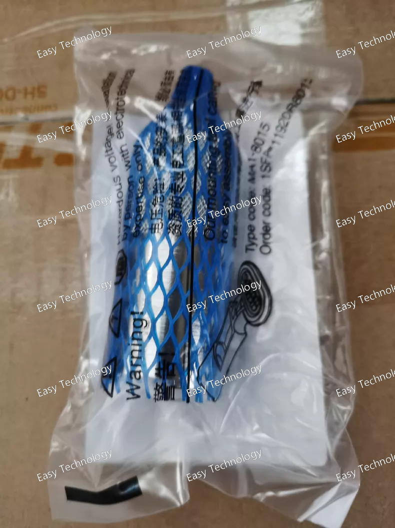
Key Parameters Parameter Specification Model / Part Number MA1‑8149 Full Ordering Code 1SFA611920R8149 Product Type Mounting Tool (Accessory) Purpose Tool for mounting 22 mm pilot devices using a power tool Compatible With 22 mm control devices such as modular and compact pushbuttons, selector switches, pilot lights, etc. Application Speed installation of panel‑mount pilot components Mounting Standard 22 mm panel cut‑out accessories Accessory Category Electrical enclosure / instrument panel tools Typical Use Industrial control panels, automation equipment, distribution panels Dimensions (approx.) ~0.029 m (W) × 0.029 m (D) × 0.089 m (H) Weight (approx.) ~0.155 kg Material Durable metal/plastic tool components Operating Conditions Standard industrial environment Function Helps secure devices into panel cut‑outs with a power driver tool
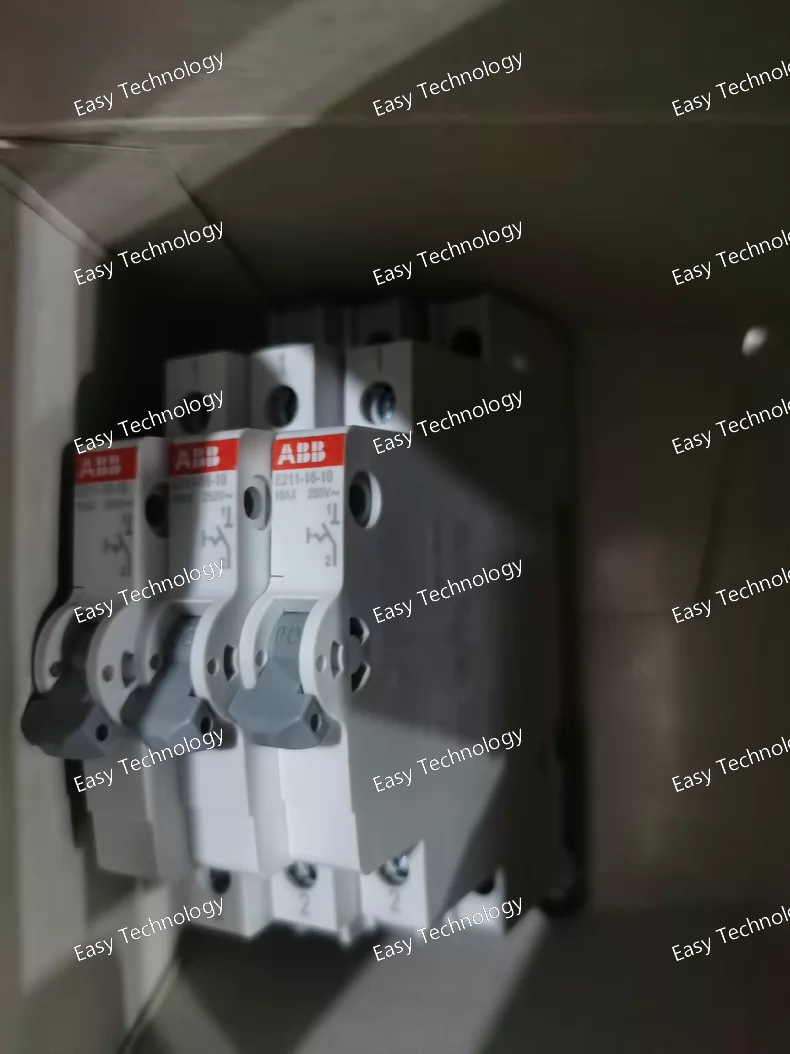
Key Parameters Parameter Specification Model / Part Number E211‑16‑10 Product Type On‑Off / Isolator Switch Contact Configuration 1 × Normally Open (1 NO) Rated Current 16 A Rated Voltage 250 / 400 V AC (AC mains) Rated Voltage (UL) 240 V AC Rated Frequency 50 / 60 Hz Impulse Withstand Voltage 6 kV Contact Positions ON / OFF Number of Poles 1‑pole Degree of Protection IP20 (terminals) Module Width 0.5 modules (≈9 mm) Mounting DIN rail panel mount Ambient Operating Temp. –25 °C to +55 °C (typical) Storage Temperature –40 °C to +70 °C Standards / Approvals EN60669‑1, EN60669‑2‑4, IEC/EN60947‑3, IEC60068 series, VDE0632, UL508 Color / Housing Grey housing Typical Depth / Height ~68 mm / ~85 mm Terminal Type Screw terminals Application Control panels, light circuits, on/off switching
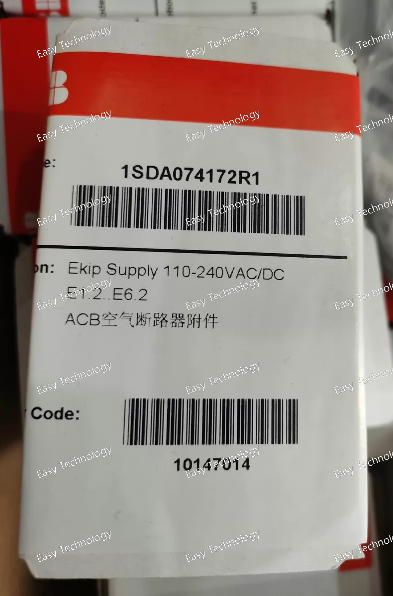
Key Parameters Parameter Specification Model / Part Number 1SDA074172R1 (EKIP SUPPLY 110‑240VAC/DC E1.2..E6.2‑XT) Product Type Power supply module (accessory for circuit breakers) Compatible With ABB SACE Emax 2 and SACE Tmax XT breakers (sizes E1.2, E2.2, E4.2, E6.2) Supply Input Voltage 110–240 V AC or DC (universal supply) Mounting / Application Installed in the terminal box of compatible breakers Function Supplies internal power to EKIP trip units and electronic modules Protection / Standards Designed for use with IEC‑standard (IEC) low‑voltage switchgear RoHS / REACH Status Compliant with EU environmental directives Net Dimensions ~120 mm (W) × 155 mm (H) × 190 mm (D) Net Weight ~0.05 kg Configuration Loose or configurable accessory module Typical Use Powering protection, monitoring, communications and auxiliary modules
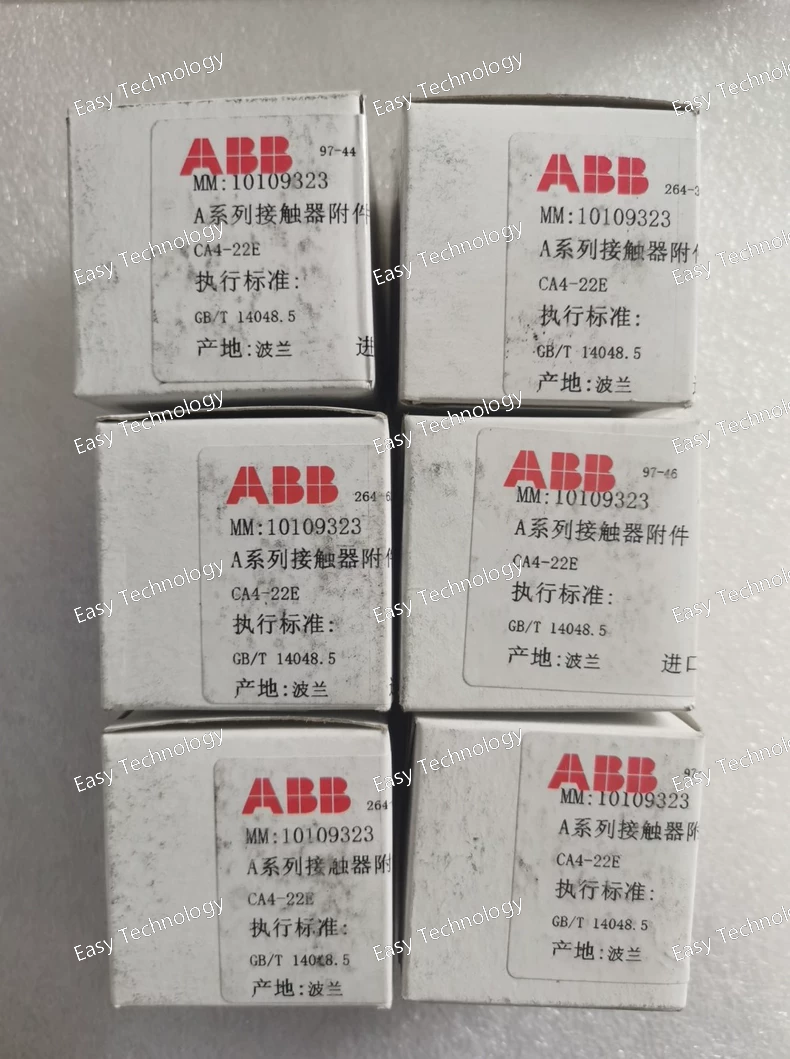
Key Parameters Parameter Specification Product Type Auxiliary contact block (front‑mounted) Model / Part Number CA4‑22E Poles / Contacts 4‑pole with 2 NO + 2 NC contacts Mounting Style Front mounting on contactor Contact Configuration Instantaneous auxiliary contacts Rated Operational Voltage (Auxiliary) Up to 690 V AC for auxiliary circuits Rated Operational Current Approx. 6 A @ 24–127 VAC; 2 A @ 500–690 VAC (AC‑15); DC ratings vary by voltage Rated Insulation Voltage (Ui) Up to 690 V (IEC standard) Rated Impulse Withstand Voltage (Uimp) Typically 6 kV Frequency 50 / 60 Hz Terminal Type Screw terminals Contact Duty Instantaneous switching for control circuits Operating Cycles ~1200 cycles/h (AC), ~900 cycles/h (DC) Compatibility Designed for use with ABB AF contactor range (e.g., AF09 through AF96) Connection Capacity Flexible and rigid conductors ~0.75–2.5 mm² Protection Class IP20 on terminals (typical) Approx. Dimensions ~46 × 46 × 46 mm (cube‑like) Approx. Weight ~0.055 kg Application Extend auxiliary contacts on contactors for control signals, interlocks, and automation logic
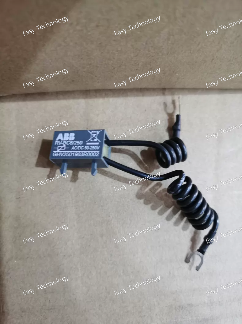
Key Parameters Parameter Specification Model / Part Number RV‑BC6/250 Product Type Varistor Surge Suppressor / Surge Protection Device Function Suppresses voltage spikes and overvoltage in control circuits Application Protection for DC coils on miniature contactors and control devices Voltage Rating Typical control circuit operation: 50‑250 V DC range Surge Absorption Limits high peak transient voltages on coils and circuits Connection Type Screw terminals or cable lug connections Suitable With Designed for contactors such as small DC‑operated contactor families Compact Size Small form factor for easy mounting on contactor frame Ambient Operating Temperature Typical industrial range (e.g., –25 °C to ~+50 °C) Mounting Directly on contactor or control accessory point Protection Role Reduces electrical noise and overvoltage stress in control coil circuits Standards / Ratings Built to typical industrial surge suppressor standards
 TEL: Grace +86 13600179521
  Mail: info@hongkongeasy.com jilineasyyi@outlook.com
 Q Q:615739355
 ADDRESS:Unit 12, 20th Floor, Good View Commercial Centre, 2-16 Garden Street, Mong Kok, Hong Kong
 whats app


