
Industrial Controller
All product are in stock,guaranteed delivery within 3-7 days.


PRODUCT
PICTURE
BRAND
DESCRIBE
STOCK
DOWNLOAD
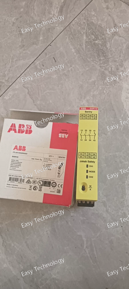
Key Technical Parameters Electrical & Safety Ratings Product / Model: ABB Sentry SSR10 24VDC Safety Relay Part Number: 2TLA010050R0000 Supply Voltage: 24 V DC Safety Output Contacts: 3 Normally Open (NO) + 1 Normally Closed (NC) Output Current Capacity: Up to ~6 A (typical maximum rated current per contact set) Reset Mode: Manual or Automatic selectable by front switch Monitored Inputs: Safety devices with contact inputs or OSSD outputs Reset Function: Selectable manual/automatic Safety Performance: Suitable for use in safety circuits requiring high integrity (e.g., PLe / SIL3 systems) Mechanical & Installation Mounting: DIN rail TH35‑15 or TH35‑7.5 (IEC standard) Terminals: Screw terminals for secure wiring Degree of Protection: IP20 (protects against solid objects) Construction Width: ~22.5 mm (1 module) Dimensions (approx): Height ~120 mm × Depth ~120 mm Weight: ~0.20 kg Typical Use & Applications Emergency stop monitoring Safety gate and interlock monitoring Safeguarding of machinery and automation systems Use with contact safety devices and OSSD output sensors Panel and control cabinet installation
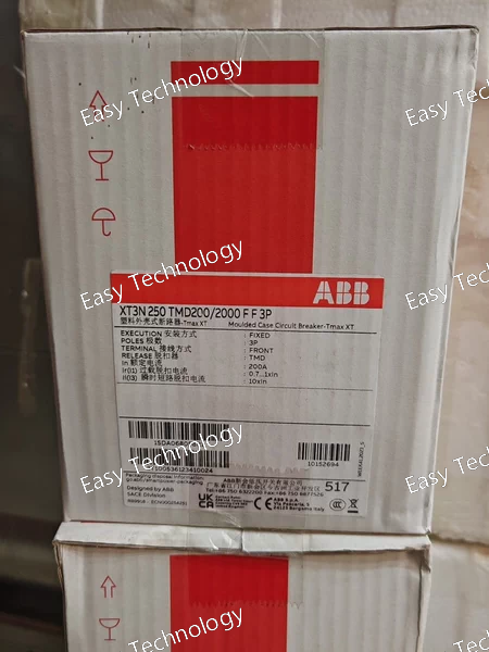
Key Technical Parameters General & Protection Product / Model: ABB XT3N250 TMD200/2000 FF 3P Device Type: Molded Case Circuit Breaker (MCCB) Series: Tmax XT Number of Poles: 3 Trip Unit Type: Thermal‑Magnetic (TMD) Mounting Style: Fixed with front terminals Current & Voltage Ratings Rated Continuous Current (In): 200 A Overload Trip Setting Range: ~140–200 A Instantaneous Short‑Circuit Setting: 2000 A Rated Operational Voltage: Up to 690 V AC or 500 V DC Rated Frequency: 50 Hz / 60 Hz Rated Insulation Voltage (Ui): ~800 V Rated Impulse Withstand Voltage (Uimp): ~8 kV Short‑Circuit & Breaking Capacity Ultimate Breaking Capacity (Icu): ~50 kA at 220–240 V AC ~36 kA at 380–415 V AC ~20 kA at 500 V AC ~5 kA at 690 V AC DC Breaking Capacity: ~36 kA at 250 V DC (2 poles in series) ~50 kA at 500 V DC (3 poles in series) Performance & Durability Electrical Durability: ~120 cycles/hour (up to ~8000 operations) Mechanical Durability: ~240 cycles/hour (up to ~25,000 operations) Power Loss: ~13 W per pole at rated conditions Terminal Type: Front, bolt connection (tightening torque ~8 N·m) Physical Dimensions (approx): ~150 mm (H) × 105 mm (W) × 70 mm (D) Weight: ~1.7 kg Degree of Protection: Standard industrial housing suitable for enclosure mounting Applications Main & feeder protection in distribution boards Motor feeder circuits protection Industrial and commercial electrical systems requiring robust overload and short‑circuit protection
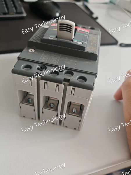
Key Technical Parameters General & Protection Product / Model: ABB XT1N160 TMD160‑1600 FF 3P Device Type: Molded Case Circuit Breaker (MCCB) Series: Tmax XT Number of Poles: 3 (three‑pole) Trip Unit Type: Thermal‑Magnetic (TMD) Mounting Style: Fixed installation, front terminal connections Current & Voltage Ratings Rated Continuous Current (In): 160 A Adjustable Instantaneous Short‑Circuit Setting: 160–1600 A Rated Operational Voltage: Up to 690 V AC / 500 V DC Rated Frequency: 50 Hz / 60 Hz Rated Insulation Voltage (Ui): ~800 V Rated Impulse Withstand Voltage (Uimp): ~8 kV Short‑Circuit & Breaking Capacities Rated Ultimate Breaking Capacity (Icu): • ~65 kA at 220–240 V AC • ~36 kA at 380–415 V AC • ~30 kA at 500 V AC • ~6 kA at 690 V AC Rated Service Breaking Capacity (Ics): Slightly lower than Icu depending on voltage DC Breaking Capability: Up to ~36 kA at 250–500 V DC Performance & Durability Electrical Durability: ~120 cycles/hour (up to ~8000 operations) Mechanical Durability: ~240 cycles/hour (up to ~25,000 operations) Power Loss: ~15 W per pole at rated operating conditions Connection / Wiring: Front panel wiring with busbar or cable lug options Environmental & Applications Typical Operational Systems: Industrial switchboards, motor feeders, main and feeder protection in commercial or industrial electrical distribution Standards Compliance: IEC 60947‑2 Use Cases: Overload protection, short‑circuit interruption, isolation in three‑phase AC and DC systems
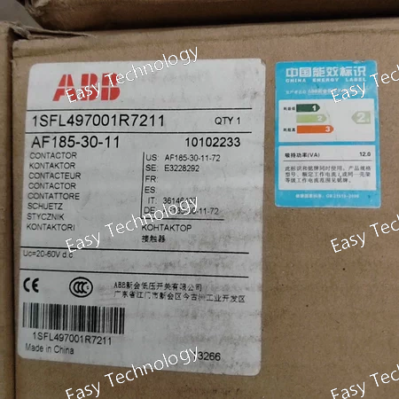
Key Technical Parameters General & Electrical Ratings Product / Model: ABB AF185‑30‑11 Device Type: 3‑pole AC Contactor Main Contacts: 3 normally open (NO) Auxiliary Contacts: 1 NO + 1 NC Control (Coil) Voltage Range: 100–250 V AC/DC Rated Insulation Voltage: Up to 690 V AC Rated Frequency: 50 Hz / 60 Hz Current & Power Ratings Conventional Free‑Air Thermal Current (Ith): ~275 A at 40 °C Rated Operational Current AC‑1 (Ie): ~275 A at 690 V AC (40 °C) ~250 A at 690 V AC (55 °C) ~180 A at 690 V AC (70 °C) Rated Operational Current AC‑3 (Ie): ~185 A at ~415–440 V AC (55 °C) ~170 A at ~500–690 V AC (55 °C) Rated Operational Power AC‑3 (Pe): ~55 kW at 220–240 V AC ~90 kW at 380–400 V AC ~110 kW at ~500 V AC ~132 kW at ~690 V AC Switching & Protection Rated Breaking Capacity (AC‑3): ~8 × Ie Rated Making Capacity (AC‑3): ~10 × Ie Rated Impulse Withstand Voltage: ~8 kV Short‑Circuit Protective Devices: gG type fuses (e.g., 355 A) Mechanical Durability: ~5 million operations Electrical Switching Frequency: ~300–1200 cycles/hour depending on duty Mechanical & Physical Mounting Type: Panel or DIN rail adapter Terminal Type: Screw terminals Degree of Protection: IP20 at coil terminals, IP00 at main terminals Operating Ambient Temperature: ~–40 °C to +70 °C (highest range when no auxiliary devices fitted) Connecting Capacity: Suitable for bar and cable connections (varied conductor sizes) Typical Applications Starting and stopping three‑phase motors Switching heavy industrial loads Control panels and motor starter assemblies Distribution and bypass circuits
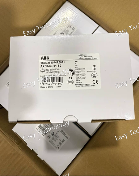
Key Technical Parameters General & Electrical Ratings Product / Model: ABB AX50‑30‑11‑80 AC Contactor Part Number: 1SBL351074R8011 Main Contacts: 3 normally open (3 NO) Auxiliary Contacts: 1 NO + 1 NC Control / Coil Voltage (Rated): 220–230 V AC at 50 Hz 230–240 V AC at 60 Hz Rated Insulation Voltage (Ui): 690 V AC Rated Frequency: 50 Hz / 60 Hz Conventional Free‑Air Thermal Current (Ith): ~100 A Degree of Protection: IP20 (terminals) Operational Currents Rated Operational Current AC‑1 (Ie): ~85 A at 220–240 V AC, 55 °C ~100 A at 690 V AC, 40 °C ~70 A at 690 V AC, 70 °C Rated Operational Current AC‑3 (Ie): ~53 A at 220–240 V AC, 55 °C ~50 A at 380–400 V AC, 55 °C ~45 A at 440–500 V AC, 55 °C ~35 A at 690 V AC, 55 °C Power Ratings Rated Operational Power (AC‑3): ~15 kW at 220–240 V AC ~22 kW at 380–400 V AC ~25 kW at 415 V AC ~25–30 kW at 440–500 V AC ~30 kW at 690 V AC Switching Frequency Electrical: ~600 cycles/hour (AC‑1 and AC‑3) Mechanical: ~3600 cycles/hour Mechanical & Physical Dimensions (approx): 108 mm (H) × 82 mm (W) × 110 mm (D) Net Weight: ~1.05 kg Terminal Type: Screw terminals Operating Ambient Temperature: ~‑40 °C to +70 °C Typical Applications Control and switching of three‑phase motors Power circuit switching up to 690 V AC Industrial control panels and motor starter assemblies General industrial and commercial power control tasks
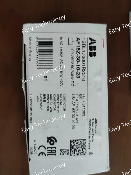
Key Technical Parameters General & Electrical Ratings Product / Model: ABB AF16Z‑30‑10‑23 Part Type: 3‑pole AC contactor Main Contact Configuration: 3 normally open (3 NO) Auxiliary Contacts: 1 normally open (1 NO) Rated Insulation Voltage: Up to 690 V AC Control (Coil) Voltage: Wide range 100 – 250 V AC/DC Rated Operational Voltage: Up to 690 V AC Rated Frequency: 50 Hz / 60 Hz Operational Current Ratings AC‑1 Load Current: ~30 A AC‑3 Motor Loads: • ~18 A at common voltages (220–440 V AC) • ~15 A at ~500 V AC • ~10.5 A at ~690 V AC Power Ratings Motor Power (AC‑3): • ~4 kW at 220–240 V AC • ~7.5 kW at 380–400 V AC • ~9 kW at 415–690 V AC Mechanical & Usage Enclosure / Protection: IP20 Terminal Type: Screw terminals Rated Insulation / Impulse Withstand: Suitable for industrial environments Switching Frequency: • ~600 cycles/hour (AC‑1) • ~1200 cycles/hour (AC‑3 / AC‑15) • ~900 cycles/hour (DC‑13) Mounting Style: Standard industrial mounting (panel or DIN rail adaptor, if required) Weight & Size: Compact design (~86 mm H × 45 mm W × 77 mm D) Applications Control and switching of motors, lighting, heating, and general power circuits Use in motor starters and control panels Suitable where wide control voltage flexibility is needed
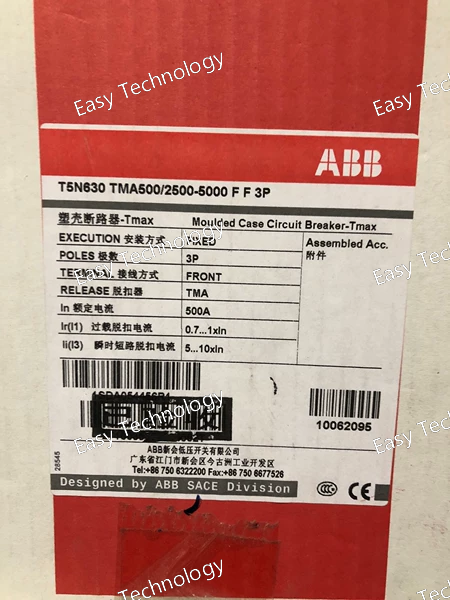
Key Technical Parameters Product / Model: ABB T5N630 TMA500/2500‑5000 FF 3P Device Type: Molded Case Circuit Breaker (MCCB) Series: SACE Tmax T5N Number of Poles: 3 (three‑pole) Mounting Style: Fixed Trip Unit Type: Thermal‑magnetic (TMA) Frame Rated Current: 630 A Rated Operational Current (In): 500 A (typical adjustment) Short‑Circuit Trip Adjustment Range: 2500–5000 A (adjustable magnetic short‑circuit trip setting) Operational Voltage: Up to 690 V AC Degree of Protection: IP20 Control / Connection: Front terminals for main circuit connections Performance Thermal‑Magnetic Protection: Provides combined overload (thermal) and short‑circuit (magnetic) protection suitable for load and fault currents. Interrupting Capacity: High breaking capacity for use in industrial power distribution systems. Application: Protection of feeders, motors, and distribution circuits in industrial or commercial installations requiring adjustable protection settings.
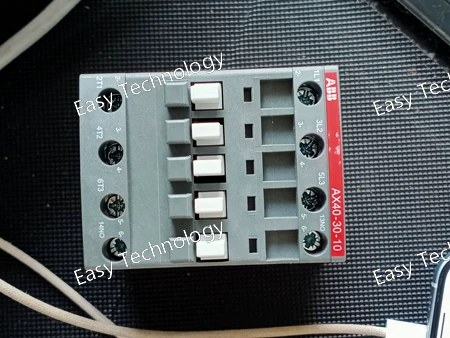
Key Technical Parameters Product / Model: ABB AX40‑30‑10‑80 AC Contactor Part Number: 1SBL321074R8010 Main Poles: 3 normally open (3 NO) Auxiliary Contact: 1 normally open (1 NO) Control / Coil Voltage: 220–230 V AC at 50 Hz; 230–240 V AC at 60 Hz Rated Insulation Voltage (Ui): 690 V AC Rated Operational Voltage (Main & Auxiliary): Up to 690 V AC Rated Frequency: 50 Hz / 60 Hz Conventional Free‑air Thermal Current (Ith): 65 A at 40 °C Current & Power Ratings Operational Current AC‑1 (Ie): ~60 A at 220–240 V AC, ~42 A at 690 V AC (70 °C) Operational Current AC‑3 (Ie): ~40 A at 220–240 V AC, ~37 A at 440 V AC, ~25 A at 690 V AC Operational Power AC‑3 (Pe): ~11 kW at 220–240 V, ~18.5 kW at 380–400 V, ~22 kW at 440–690 V Switching & Mechanical Rated Operational Current AC‑15: up to ~6 A at low control voltages Maximum Electrical Switching Frequency: ~600 cycles/hour (AC‑1), ~1200 cycles/hour (AC‑3 / AC‑15), ~900 cycles/hour (DC‑13) Maximum Mechanical Switching Frequency: ~3600 cycles/hour Physical & Environmental Dimensions (H × W × D): ~108.3 mm × 54 mm × 90 mm Weight: ~0.667 kg Degree of Protection: IP20 Terminal Type: Screw terminals Ambient Temperature (Operation): –40 °C to +70 °C Altitude Capability: up to ~3000 m without derating Applications Motor control starters Switching three‑phase power circuits Industrial control panels Lighting and auxiliary loads
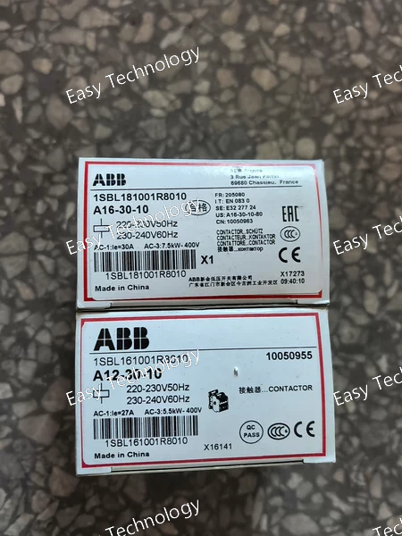
Key Technical Parameters General & Electrical Ratings Product / Model: ABB A16‑30‑10 Contactor Part Number: 1SBL181001R8010 Main Poles: 3 normally open (3 NO) Auxiliary Contact: 1 normally open (1 NO) Control/Coil Voltage (Rated): 220 – 230 V AC at 50 Hz 230 – 240 V AC at 60 Hz Rated Operational Voltage (Main Circuit): Up to 690 V AC Rated Operational Current (AC‑3): ~17 A at ~220–240 V AC ~17 A at ~380–400 V AC ~16 A at ~440 V AC Lower currents at higher voltages (500–690 V) Performance & Power Rated Operational Power (AC‑3): ~4 kW at ~220–240 V AC ~7.5–9 kW at ~380–440 V AC ~9 kW up to 690 V AC Rated Operational Current (AC‑1): ~30 A at 690 V AC (at 40 °C) Rated Operational Current (AC‑15): Suitable for control and signaling loads (e.g., ~4 A at 220–240 V AC) Rated Operational Current (DC‑13): Suitable for DC control applications (various values depending on voltage) Rated Breaking & Making Capacity: Making: ~10 × Ie (AC‑3) Breaking: ~8 × Ie (AC‑3) Mechanical & Connection Mounting: DIN‑rail or screw mounting Connection Terminals: Screw terminals for both main and auxiliary circuits Dimensions: Approx. 44 mm (width) × 74 mm (height) × 74 mm (depth) Weight: Approx. 0.34 kg Switching Frequency: AC‑1: ~600 cycles/hour AC‑3: ~1200 cycles/hour Mechanical Switching Frequency: ~3600 cycles/hour Coil & Operating Coil Power Consumption: Holding: ~8 V·A Pull‑in: ~70–74 V·A Operate / Release Times: Operate: ~10–26 ms Release: ~4–11 ms Standards & Ratings Standards Compliance: IEC 60947‑1 and IEC 60947‑4‑1 (general industrial contactor standards) Insulation Voltage: ~1000 V (IEC rating) Impulse Withstand Voltage: ~8 kV Environmental: Ambient operation typically from ~‑40 °C to ~+55 … +70 °C depending on conditions Degree of Protection: IP20 on main, auxiliary, and coil terminals Typical Applications Motor control starters and reversing arrangements Switching of lighting, heating, and small industrial loads General power circuit control in machine panels Interlocking and auxiliary switching functions
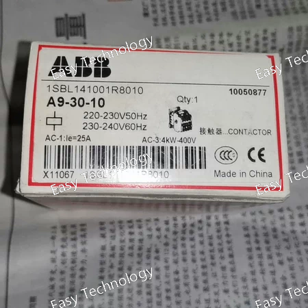
Key Technical Parameters General & Electrical Ratings Product / Model: A9‑30‑10 Contactor Part Number: 1SBL141001R8010 Main Circuit Poles: 3 poles (3NO main contacts) Auxiliary Contacts: 1 normally open (NO) auxiliary contact Rated Operational Voltage (Main Circuit): Up to ~690 V AC Control/Coil Voltage: 220–230 V AC at 50 Hz 230–240 V AC at 60 Hz Control Voltage Type: AC coil operation Rated Operational Current (AC‑3): ~9 A at 400–440 V Rated Operational Power (AC‑3): ~4 kW at 400 V (lower at 230 V) General Use Rating (UL/CSA): ~21 A at 600 V AC Horsepower Rating (Typical): ~2 hp at 220–240 V AC ~5–7.5 hp at higher voltages (440–600 V) Mechanical / Physical Design Type: Block‑type magnetic contactor Mounting: Panel or DIN rail compatible Connection: Screw terminals Coil Operating Range: Accepts standard AC supply in specified voltage bands Use Category: Suitable for AC‑3 motor load duties and general switching Applications Motor Control: Starting and stopping three‑phase induction motors Switching Power Circuits: Control of lighting, resistive loads, and capacitor banks Industrial & Commercial Control Panels: Widely used in automation and machinery installations
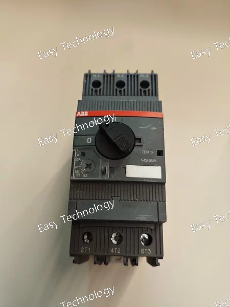
Key Technical Parameters General & Electrical Ratings Product Type: Manual Motor Starter / Motor Protection Switch Series: MS165 Current Setting Range: 52 – 65 A Poles: 3‑pole (three phases) Rated Operational Current: 65 A Rated Operating Voltage (Main Circuit): Up to 690 V AC Rated Frequency: 50/60 Hz Rated Operational Power (AC‑3): ~30 kW at 230 V / ~30 kW at 400 V Overload Protection: Thermomagnetic (trip class 10) Phase Failure Sensitive: Yes Trip Free Mechanism: Yes Disconnect Function: Yes Setting Adjustability: Adjustable and sealable current setting Action / Handle: Rotary handle with clear ON / OFF / TRIP indication Short‑Circuit & Protection Short‑Circuit Interrupting Capacity: Typically high (design for safe interruption up to standards for motor starters) Phase Loss / Overload Protection: Built‑in sensitivity and thermal / magnetic protect Manual Operation: ON / OFF switching with automatic trip response Mechanical & Environmental Connection Type: Screw terminals Mounting Type: DIN‑rail or panel mount Enclosure / Protection: IP20 (housing) Operating Temperature: Approximately –25 °C to +60 °C Operating Cycles: Roughly 25,000 electrical, 50,000 mechanical Dimensions: Compact — approximate width ~55 mm Applications Protection and Control: Provides manual motor starting, overload protection, phase failure detection, and short‑circuit reaction without requiring separate fuses. Installation: Suitable for industrial control panels, motor starters, pump and compressor protections, HVAC systems, and general power circuits where motor protection is required.
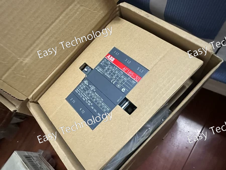
Key Technical Parameters (English) General & Electrical Ratings Part Number: 1SFL497001R7011 Series / Type: AF185‑30‑11 contactor Configuration: 3‑pole, normally open main contacts (3 NO) Auxiliary Contacts: 1 normally open + 1 normally closed Control / Coil Voltage: 100–250 V AC and 100–250 V DC (50/60 Hz) Operating Voltage Type: AC/DC Rated Operational Voltage (Main Circuit): up to ~690 V Rated Operational Current (AC‑1 at 400 V): ~275 A Rated Operational Current (AC‑3 at 400 V): ~185 A Rated Operational Power (AC‑3 at 400 V): ~90 kW Number of Poles: 3P Mounting Type: Rail or panel mounting depending on application (standard industrial contactor). Mechanical & Physical Weight: ~2.9 kg Dimensions (approx.): • Width ~111.5 mm • Height ~196 mm • Depth ~160 mm Connection Type: Rail connection (busbar or terminal blocks typical) Suitable Max Voltage: Up to 1000 V nominal (application dependent) Main Contacts: 3 NO Auxiliary Contacts: 1 NO + 1 NC Application & Environment Designed for industrial control panels, motor starters, isolating circuits, and distribution systems. Compatible with both 50 Hz and 60 Hz systems. AC/DC coil allows flexible control supply installations. Suitable for general switching duties and moderate load applications typical of motors and industrial machinery.
 TEL: Grace +86 13600179521
  Mail:jilineasyyi@outlook.com
 Q Q:info@hongkongeasy.com
 ADDRESS:Unit 12, 20th Floor, Good View Commercial Centre, 2-16 Garden Street, Mong Kok, Hong Kong
 whats app


