
Industrial Controller
All product are in stock,guaranteed delivery within 3-7 days.


PRODUCT
PICTURE
BRAND
DESCRIBE
STOCK
DOWNLOAD
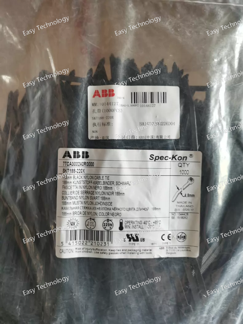
Typical Parameters Parameter Symbol Typical Value / Description Module Type - Phase-Control Thyristor Module (Half-Controlled Bridge) Circuit Configuration - T21 (Two thyristors + two diodes, forming a half-controlled bridge leg). Repetitive Peak Off-State Voltage VDRM / VRRM 800 V to 1600 V (Common ratings: 1200V, 1400V, 1600V). Average On-State Current (Per Thyristor) IT(AV) 220 A (At a specified case temperature, e.g., Tc=80°C). This is likely the rated current indicated by "220" in the model. RMS On-State Current IT(RMS) ~ 347 A (Approx. π * IT(AV) for sine wave conduction). Non-Repetitive Peak Surge Current ITSM 3000 A to 4000 A (Typical for 10 ms half-sine wave). Gate Trigger Current IGT 200 mA (Typical). Gate Trigger Voltage VGT 1.5 V (Typical). Thermal Resistance, Junction-to-Case Rth(j-c) 0.08 °C/W to 0.12 °C/W (Per thyristor/diode, typical). Isolation Voltage Visol 2500 V RMS (Min., baseplate to terminals). Mounting - Module with isolated baseplate for screw mounting onto a heatsink with thermal grease. Terminals - Screw terminals for main power (AC input, DC output) and gate control signals. Operating Junction Temperature Tj -40 °C to +125 °C (Standard range).
Typical Parameters Parameter Description / Typical Value Module Type Fail-Safe Digital Input Module System Compatibility ABB Freelance DCS, AC 800F Controller, S800 I/O or F-I/O Series. Number of Channels 16 channels (common for this form factor). Input Type Dry Contact (volt-free contact) or Wet Contact (sourcing DC voltage). Nominal Input Voltage 24 VDC (most common). Also available in versions for 48 VDC and 125 VDC. Input Signal Level "0" (OFF): Typically < 5V DC. "1" (ON): Typically 15-30V DC (for 24V nominal). Input Current Typically ~5-10 mA per channel (at nominal voltage). Isolation Channel-to-Channel: Yes (typically 500V AC). Channel-to-Bus: Yes (optical isolation). Diagnostics Yes. Includes wire-break/short-circuit detection, module failure, and communication loss. Update Time Very fast, typically 1-10 ms per module (configurable). Backplane Bus S800 I/O Bus or Profibus-DP/PA, depending on the specific system configuration and the interface module used (e.g., CI871). Power Supply Requires 24 VDC for internal electronics, typically sourced from the system power supply or the field side. LED Indicators Per-channel status LEDs (Green/Red) and module status LEDs (RUN, ERR, etc.). Certifications Complies with CE, UL, cUL, and relevant industrial standards (IEC 61131).
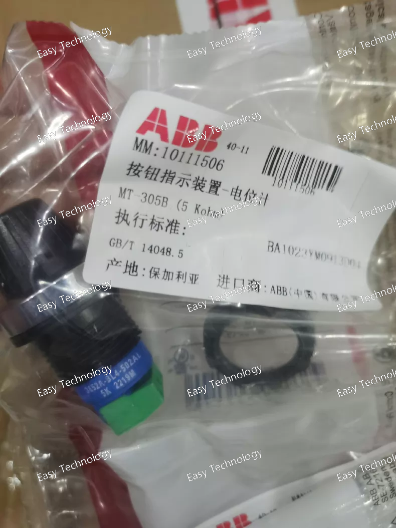
Typical Parameters Parameter Description / Typical Value Model / Type MT-305B - NTC Thermistor Probe Resistance Value 5 kΩ (Kilo-ohms) at a specified reference temperature (e.g., R₂₅ = 5kΩ @ 25°C). This is the most critical parameter. Beta Value (β) A specific constant (e.g., 3470K, 3950K) that defines the resistance-temperature curve/characteristic. Essential for accurate temperature calculation. Tolerance Resistance tolerance at reference temperature (e.g., ±1%, ±5%). Defines measurement accuracy. Temperature Range Operating Range: Typically -50°C to +150°C (common for epoxy-coated NTCs). Exact range depends on construction. Probe Material & Construction Stainless steel sheath, epoxy-coated bead, or glass-encapsulated. Determines response time and environmental durability. Lead Wires Insulated copper wires (e.g., PVC, Teflon), specified length. Time Constant The time required for the sensor to respond to 63.2% of a step change in temperature (e.g., a few seconds in air or liquid). Dissipation Constant The power required to raise the thermistor's temperature by 1°C above its surroundings (in mW/°C). Important for self-heating error consideration. Application Temperature sensing in HVAC controls, battery packs, electronic assemblies, industrial processes, and consumer appliances.
Typical Parameters Parameter Description / Inferred Value Model Series MJS Series (Standard Cast Iron Motor) Motor Type Three-Phase, Squirrel Cage Induction Motor Rated Output Power 0.75 kW (1 HP) *[Common interpretation: "60" often indicates ~0.75kW/1HP in this series.]* Number of Poles 4 *[Suffix "B" in older ABB codes typically denotes 4-pole.]* Synchronous Speed 1500 rpm (at 50Hz) Rated Speed ~1400 rpm (at 50Hz, 4-pole) Supply Voltage & Frequency 400 V, 3-phase, 50 Hz (Most common. May also be designed for 415V, 380V, or 460V/60Hz). Rated Current ~1.8 A (approximate at 400V, 50Hz, 0.75kW) Efficiency Class IE2 (High Efficiency) – Standard for its manufacturing period. Insulation Class Class F (with temperature rise according to Class B). Protection Class (IP) IP55 (Dust protected and protected against water jets). Cooling Method (IC) IC 411 (Totally Enclosed Fan Cooled - TEFC). Mounting (IM) IM B3 (Standard foot-mounted). Duty Cycle S1 (Continuous duty). Ambient Temperature Max. 40°C (standard). Altitude Max. 1000 m above sea level (standard). Connection Star (Y) / Delta (Δ) – Terminal board usually allows connection changes for different voltages.
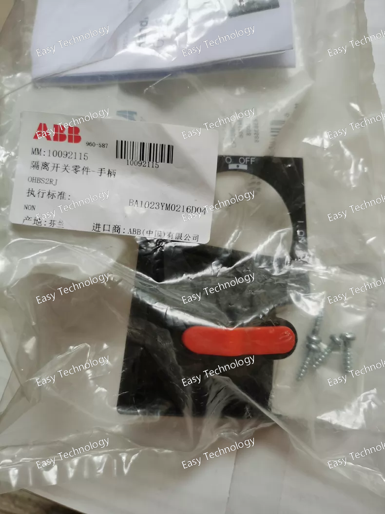
Parameter Description / Typical Range Model Series OHB / HXR Series (High Voltage Motors) Type Three-Phase, Squirrel Cage, High Voltage Induction Motor Rated Output Power ~ 200 kW to 1000+ kW (The "S2" often indicates a specific frame size range for higher power, e.g., ~400-800 kW). Rated Voltage 3300 V, 6600 V, 11000 V (or other standard MV levels like 4160V, 13800V depending on region). Frequency 50 Hz or 60 Hz. Number of Poles 4, 6, 8, 10, or 12 poles (对应同步转速: 1500, 1000, 750, 600, 500 rpm @ 50Hz). Rated Speed Depends on poles (e.g., ~1485 rpm for 4-pole, ~990 rpm for 6-pole @ 50Hz). Insulation Class Class F (with temperature rise according to Class B for long life). Protection Class IP54 or IP55 (common for high voltage motors). Cooling Method IC 81W (Air-cooled, with integrated air-to-water heat exchanger) or IC 611 (Closed air circuit with air/air cooler) for dirty environments. Mounting IM B3 (Foot-mounted) is standard. IM B35 (Foot and flange) is also common. Service Factor / Duty Cycle S1 (Continuous duty). Starting Method Designed for direct-on-line (DOL) starting or with soft starters/VSDs. Ambient Temperature Max. 40°C (standard). Higher ambient options available. Altitude Up to 1000 m above sea level (standard). Efficiency Complies with IE3 (Premium Efficiency) or higher (IE4) per IEC 60034-30-1 for high voltage motors. Standards Designed to IEC 60034 standards. May also meet IEEE 841 (for severe duty) or API 541 (for oil & gas) upon request.
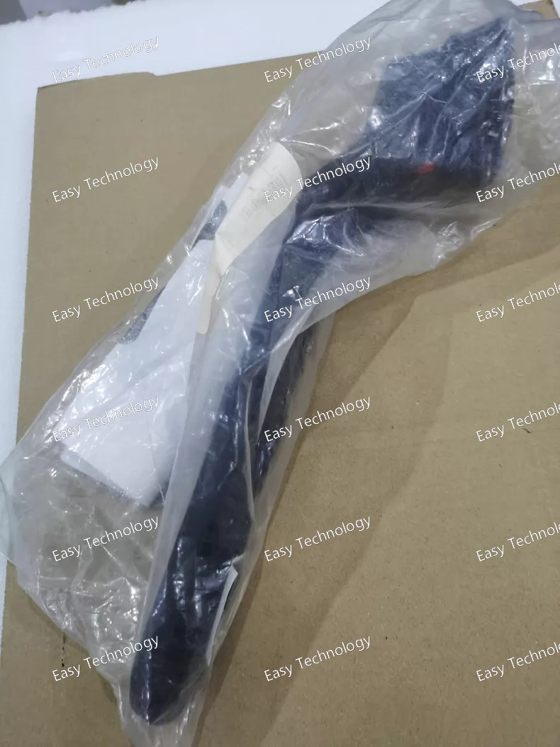
Key Parameters Parameter Description / Typical Value Model OHB274J12 Type Three-Phase Squirrel Cage Induction Motor Output Power 15 kW (20 HP) *[Note: "274" in ABB coding often corresponds to 15kW/20HP frame]* Rated Voltage 400 V (or other standard voltages like 690V, depending on design region) Frequency 50 Hz (or 60 Hz, or dual-frequency) Rated Speed ~1470 rpm (for 4-pole design at 50Hz) Number of Poles 4 (Synchronous speed: 1500 rpm @ 50Hz) Rated Current ~28-30 A (at 400V, 50Hz) [Exact value depends on efficiency & power factor] Efficiency Class IE3 (Premium Efficiency) or IE2 (High Efficiency) per IEC 60034-30 standards. Insulation Class F (with temperature rise according to Class B, ensuring long life). Protection Class IP55 (Dust protected and protected against water jets from any direction). Cooling Method IC 411 (Totally Enclosed Fan Cooled - TEFC). Mounting IM B3 (Foot-mounted) or IM B35 (Foot-mounted with flange) - common variants. Ambient Temperature Max. 40°C (as standard). Altitude Max. 1000 m above sea level (as standard). Duty Cycle S1 (Continuous duty). Standards Designed in accordance with IEC standards (e.g., IEC 60034). Design Standard N-design (normal starting torque, normal starting current, low slip).
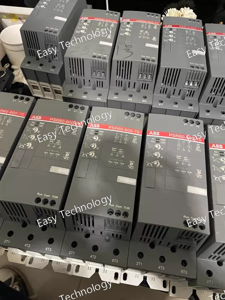
Parameter Value / Description Explanation Series / Range PSR (Programmable Safety Relay) ABB's comprehensive family of modular safety relays. Product Type Safety Relay Module (Function Module) Provides specific safety logic. Requires a base unit and power supply. Model Number PSR60-600-70 Code Breakdown: - PSR60: Series designation (PSR) and base unit compatibility (60mm wide). - 600: Indicates a dual-channel safety function module with cross-circuit monitoring. - 70: Specific variant, often denotes a 2-channel module with manual start (S33-S34). Safety Function Two-hand control, EMERGENCY STOP, Safety gate monitoring Monitors two independent signal paths. Requires complementary (N/O and N/C) contacts from each safety device for cross-fault detection. Safety Integrity • Safety Category: 4 (EN 954-1) • Performance Level (PL): PL e (EN ISO 13849-1) • Safety Integrity Level (SIL): SIL 3 (EN/IEC 62061) Meets the highest levels of safety for machinery control systems. Supply Voltage 24V DC (via the base unit) Standard voltage for industrial control circuits. Number of Channels 2 (Dual Channel) Can monitor two independent safety inputs (e.g., two contacts from a safety gate). Input Type Cross-circuit monitoring Requires both a Normally Open (NO) and a Normally Closed (NC) contact from each safety device to detect contact welding or faults. Outputs • Safety Outputs: 2 or 3 semiconductor safety outputs (OSSDs - Output Signal Switching Devices), typically via the base unit. • Auxiliary Outputs: At least one signaling contact for fault or status indication. Safety outputs are force-guided (mechanically linked) relays to ensure safe switching. Start Function Manual Start (with monitored start option) After a safety trip, the circuit requires a deliberate manual reset (via a separate reset button) to restart. The start circuit itself can be monitored. Time Delay Typically not applicable for this basic function module. Other PSR modules offer timed functions. Dimensions (Module) Approx. 22.5mm wide (single module) Designed to be snapped onto a DIN rail-mounted base unit (e.g., PSR-TB60). Connection Spring-cage or screw terminal (via base unit) Standards Compliance EN 60204-1, EN 954-1, EN ISO 13849-1, EN/IEC 62061, UL 508, CSA C22.2 Complies with international machinery safety and control standards. Ambient Temperature -25°C to +55°C (operation) Standard industrial operating range.
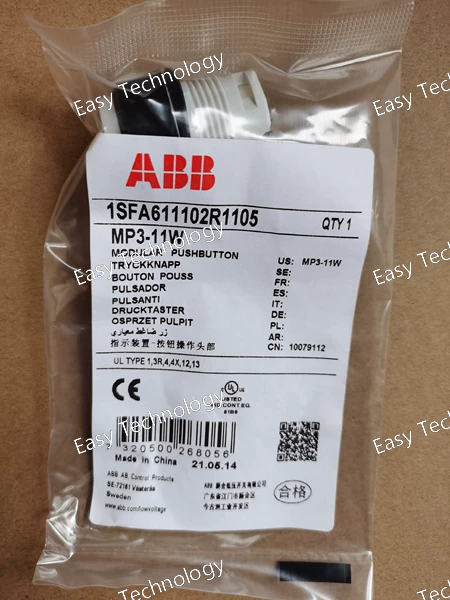
Parameter Value / Description Explanation Series / Range MetaPRO ABB's advanced series for distribution board instrumentation and measurement. Product Type Intelligent Incoming Line Measurement & Protection Unit Combines metering, monitoring, and protection in one device. Model Number MP3-11W Code Breakdown: - MP3: MetaPRO series, 3-phase. - 1: Standard frame size / variant. - 1: Specific function set (indicating basic measurement/protection). - W: Built-in high-precision energy metering (kWh, kVArh). System Type 3-Phase, 4-Wire (3P4W) Designed for systems with three phases and a neutral. Measurement Inputs • 3 Current (via CTs) • 4 Voltage (3Ph-N) Direct connection to voltage; current measured via external Current Transformers (CTs). Rated Voltage (U<sub>n</sub>) 3 x 57.7/100V, 3 x 230/400V AC Standard measurement voltages. Must match PT outputs or system voltage directly. Rated Current (I<sub>n</sub>) 1A or 5A (via CTs) Depends on the connected Current Transformers. Measurement Accuracy • Energy (Active/Reactive): Class 0.5S (per IEC 62053-22) • Voltage/Current/Power: Typically ±0.5% The “0.5S class” is a high-accuracy standard suitable for billing purposes. Core Functions Measurement: • All electrical parameters (V, I, kW, kVA, kVAr, PF, Hz) • Energy import/export (kWh, kVArh) • Demand (MD) • Power quality (THD, unbalance) Protection: • Over/Under Voltage • Over/Under Frequency • Over Current (basic) Provides a complete dashboard of system health and consumption. Communication • RS485 serial communication (standard) • Protocols: Modbus RTU Allows integration into SCADA, BMS, or ABB’s own energy management systems. Power Supply Auxiliary supply: Typically 24-240V AC/DC (wide range) Powers the internal electronics independently. Display Multi-line LCD Display Local readout of all measured values, energy totals, and status. Mounting Panel Mounting Designed for cut-out mounting on a switchboard door or panel. Standards Compliance IEC 61557-12 (Electrical safety), IEC 62053-22 (Metering accuracy), IEC 61010-1 (Safety)
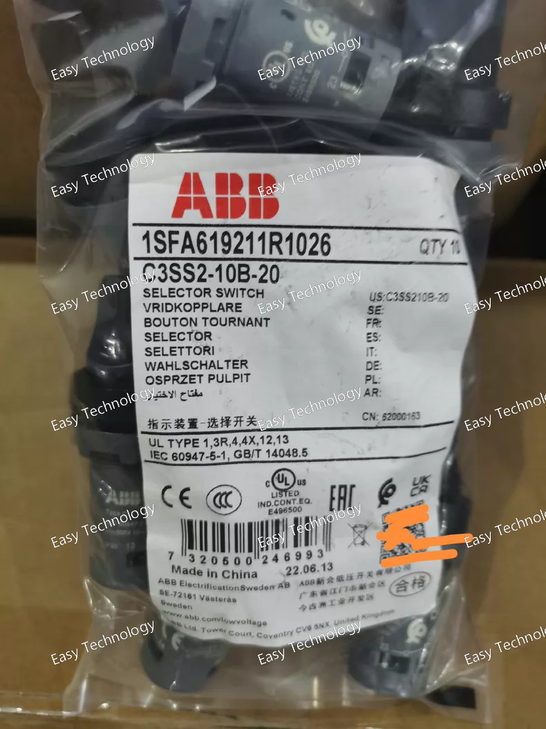
Technical Specifications Parameter Value / Description Explanation Series / Range System Pro M compact ABB's mainstream, compact distribution equipment series. Product Type Miniature Circuit Breaker (MCB) Core function: Protection against overload and short circuit. Model Breakdown C3SS2-10B-20 Code Decoded: - C3: Product family/design platform. - SS2: "S" for MCB, "S2" indicates a 2-pole device. - 10: Breaking Capacity = 10 kA (I<sub>cn</sub>). - B: Tripping Characteristic = Type B. - 20: Rated Current = 20 Amperes. Number of Poles 2 Poles (1+N) "1" = Fully protected phase pole. "N" = Neutral pole (primarily for isolation). Rated Current (I<sub>n</sub>) 20 A The continuous current the device is designed to carry. Rated Voltage (U<sub>e</sub>) 230/400V AC Suitable for single-phase (230V) and three-phase (400V) systems. Tripping Characteristic Type B Trips between 3x and 5x I<sub>n</sub> (60A to 100A). For general use: lighting, sockets, residential circuits. Breaking Capacity (I<sub>cn</sub>) 10 kA Maximum short-circuit current it can safely interrupt at rated voltage. Insulation Voltage (U<sub>i</sub>) 500V Rated insulation voltage. Impulse Withstand Voltage (U<sub>imp</sub>) 4 kV Resistance to voltage surges (e.g., from lightning). Pollution Degree 2 For normal indoor environments. Mounting DIN Rail Mounting Standard 35mm top-hat (TS35) DIN rail. Standards Compliance IEC/EN 60898-1 IEC/EN 60947-2 International and European standards for circuit-breakers. Terminals Screw Clamp Terminals Suitable for rigid and flexible conductors (check local guidelines for torque). Electrical Life Typically >10,000 cycles Mechanical and electrical endurance. Ambient Temperature -25°C to +55°C (for calibration) Operating temperature range. Storage Temperature -40°C to +70°C Approximated Dimensions (W x H x D) ~36mm x 78mm x 70mm 2-module width on a DIN rail.
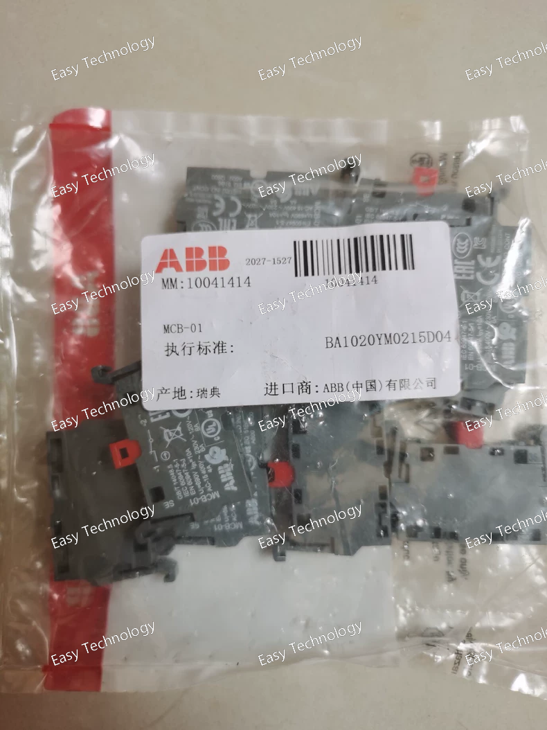
Key Parameters Category Parameter Specification / Description General Model ABBMCB-01 Compatible Breakers ABB Emax 2 series air circuit breakers (ACBs) Primary Function Communication interface for monitoring and control Electrical Supply Voltage Typically powered directly from the breaker (auxiliary voltage), e.g., 24-250 V AC/DC. (Must be verified with the official datasheet for the specific version.) Power Consumption Low power, sourced from the breaker's auxiliary supply. Communication Primary Protocol Modbus RTU Physical Interface RS-485 (2-wire, half-duplex) Address Range Configurable Modbus slave address (typically 1-247) Baud Rate Configurable (e.g., 9600, 19200, 38400, 57600, 115200 bps) Parity Configurable (None, Even, Odd) Data & Functions Monitored Parameters Current (IL1, IL2, IL3, IN), Voltage (VLN, VLL), Power (kW, kVAR, kVA), Energy (kWh, kVARh), Frequency, Power Factor, etc. Status Information Breaker position (Open/Closed), Spring charging state, Ready to Close, Alarm/Trip status. Control Commands Remote OPEN, REMOTE CLOSE (subject to interlock and authorization). Protection Data Read (and sometimes set) protection thresholds, view trip logs and event history. Alarms System warnings, pre-alarms, and trip alarms. Mechanical & Environmental Mounting Direct plug-in or fixed mounting on the Emax 2 breaker. Operating Temperature -25°C to +70°C (typical for industrial environments) Standards & Approvals Complies with relevant IEC/EN standards for industrial equipment.
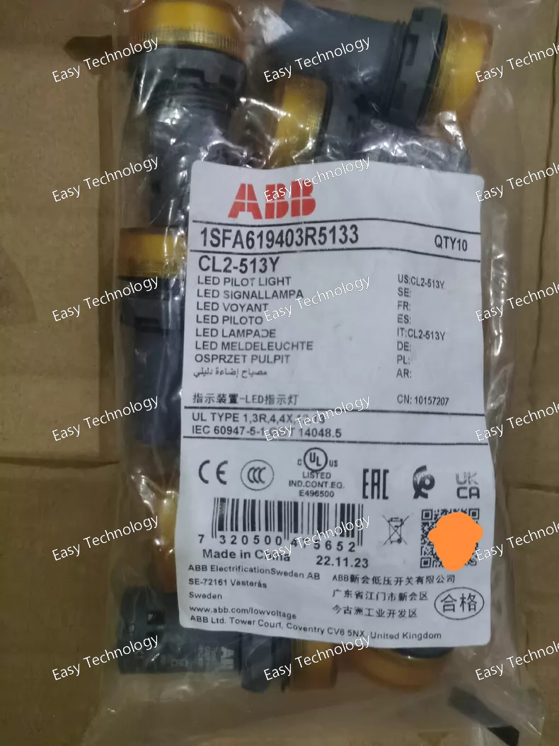
Key Parameters Parameter Specification Model / Part Number CL2‑513Y (ABB) ABB Ordering Code 1SFA619403R5133 Product Type Compact Illuminated Pilot Light Indicator Color Yellow Light Source Integrated LED (no separate bulb) Rated Operational Voltage 110 – 130 V AC Rated Frequency 50 / 60 Hz Rated Current ~15–17 mA at 110–130 V AC Mounting Hole Diameter 22 mm standard panel cut‑out Degree of Protection (Front) IP66 / IP67 / IP69K Degree of Protection (Terminals) IP20 Connection Type Screw clamp terminals Terminal Torque ~0.9 N·m Wire Stripping Length ~8 mm Ambient Operating Temperature –25 °C to +70 °C Storage Temperature –40 °C to +85 °C Pollution Degree 3 Body Color / Housing Gray/black body with yellow lens Net Weight ~0.018 kg
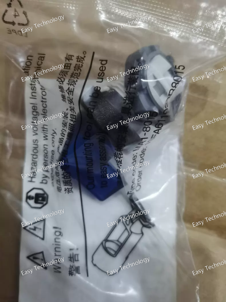
Key Parameters Parameter Specification Model / Part Number M2SS4‑11L (ABB) Catalog / Ordering Code 1SFA611203R1104 Product Type Modular Illuminated Selector Switch Actuator Color Blue Number of Positions 2 Positions (Maintained) Handle Style Long handle (rotary) Illumination Illuminated (LED ready, requires LED block) Contact Blocks Not included (modular design) Mounting Cut‑out 22 mm panel hole Bezel Material Black plastic Operator Function Maintained (latching) Protection Degree (Front) High ingress protection (e.g., IP66/67/69K) typical for modular pilot devices Mechanical Durability Designed for high mechanical reliability Ambient Operating Temperature –25 °C to +70 °C typical Storage Temperature –40 °C to +85 °C typical Usage Manual selector for control logic, mode selection, and operator input
 TEL: Grace +86 13600179521
  Mail:jilineasyyi@outlook.com
 Q Q:info@hongkongeasy.com
 ADDRESS:Unit 12, 20th Floor, Good View Commercial Centre, 2-16 Garden Street, Mong Kok, Hong Kong
 whats app


