
Industrial Controller
All product are in stock,guaranteed delivery within 3-7 days.


PRODUCT
PICTURE
BRAND
DESCRIBE
STOCK
DOWNLOAD
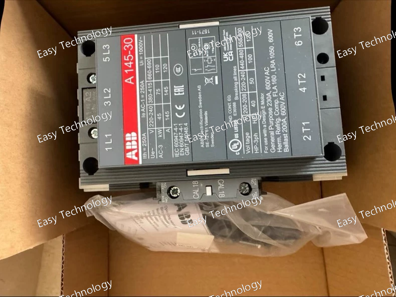
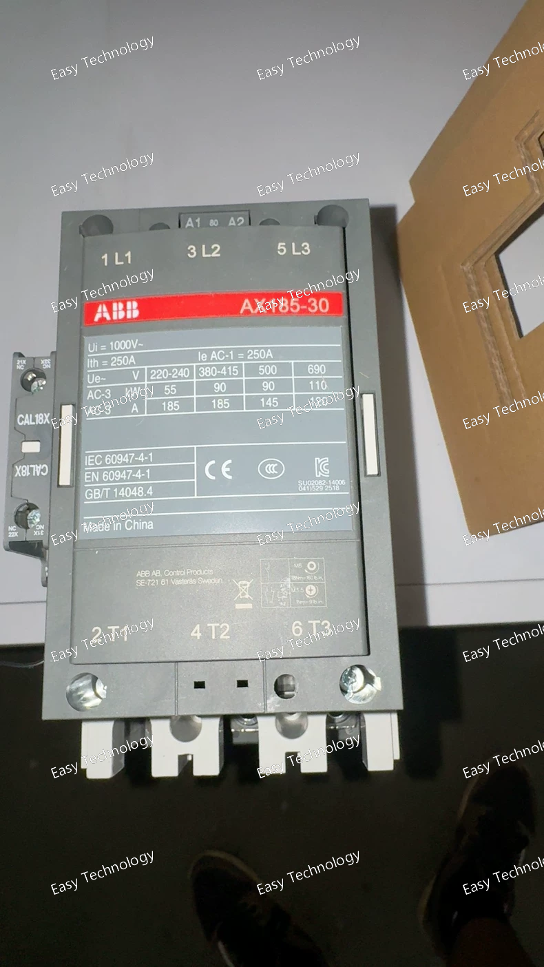
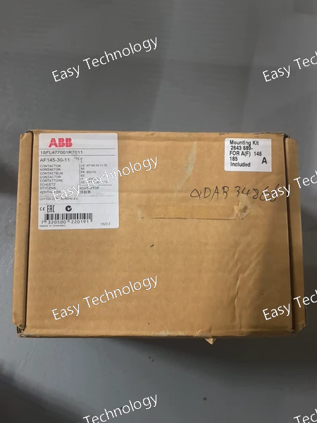
Technical Parameters Parameter Specification Manufacturer ABB Part Number 1SFL471001R8011 Product Type Three‑Phase Power Contactor Series / Model A145‑30‑11‑80 Number of Poles 3 (three‑phase main contacts) Main Contacts (NO/NC) 3 NO, 0 NC Auxiliary Contacts (NO/NC) 1 NO + 1 NC Rated Control Coil Voltage 220–230 V AC (50 Hz) / 230–240 V AC (60 Hz) Rated Operational Voltage (Main Circuit) Up to 690 V AC Rated Operational Current AC‑1 Up to ~250 A at 690 V Rated Operational Current AC‑3 ~145 A at 400 V Rated Insulation Voltage ~1000 V AC Rated Frequency 50 / 60 Hz Connection Type Rail or screw terminal connections Mechanical Durability Designed for frequent industrial operation Weight ~3.5 kg Typical Application Motor control, switching of power circuits, industrial control systems
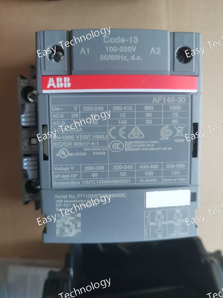
Technical Parameters Parameter Specification Manufacturer ABB Product Type Three‑Phase Power Contactor Series / Family AF Series Model Variant AF146‑30‑11 (e.g., non‑reversing contactor with auxiliary contacts) Number of Poles 3 main contacts (3NO) Auxiliary Contacts 1 NO + 1 NC Control / Coil Voltage Range Wide‑range electronic coil (e.g., 24–60 V AC and 20–60 V DC or other variants available) Nominal Operational Voltage (Main Circuit) Up to 1000 V AC (IEC) / ~600 V AC (UL) Rated Operational Current AC‑1 ~200–225 A (general use) Rated Operational Current AC‑3 ~146 A (motor switching) Rated Operational Power (AC‑3) Up to around 75–90 kW (depending on voltage) Rated Motor Power (Typical) ~45 kW @ 230 V AC, ~75–90 kW @ 380–690 V AC Frame Size / Designation AF146 Contact Configuration Main contacts 3NO, includes auxiliary contacts Insulation Voltage (Ui) Up to ~1000 V Control Frequency 50 / 60 Hz (for AC coil variants) Termination / Connection Screw terminals / double clamps Mounting Panel / base mounting Typical Applications Motor control, starting/stopping, power switching in industrial control panels Approximate Weight Moderate industrial contactor size (around ~1.7–2 kg depending on variant) Coil Technology Electronic coil interface with built‑in surge suppression and low holding power
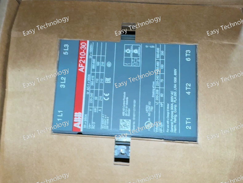
Technical Parameters Parameter Specification Manufacturer ABB Part Number 1SFL517001R7211 Model / Series AF210‑30‑11 Product Type Three‑phase power contactor Number of Poles (Main Contacts) 3 normally open (3 NO) Auxiliary Contacts 1 normally open (NO) + 1 normally closed (NC) Control Coil Voltage DC 20 – 60 V Coil Voltage Type Direct Current (DC) Rated Operational Voltage (Main Circuit) Up to ~690 V AC Rated Operational Current (AC‑3) ~210 A at 400 V AC Rated Operational Power (AC‑3) ~110 kW at 400 V AC Connection Type Busbar or screw type main power terminals Auxiliary Connection Screw‑type control/auxiliary terminations Frequency (Main Circuit) 50 / 60 Hz Mounting Panel / base mounting Typical Application Motor starting/stopping, isolation, bypass switching in control panels Physical Size / Weight Industrial block contactor size (approx. 5 kg)
Technical Data: Series: ABB A-series (AF Contactor Family) Rated Operational Current (Ie): AC-3 (Squirrel Cage Motor Switching): 370 A at 400/415V AC AC-1 (Resistive Load Switching): 450 A at 400/415V AC Rated Insulation Voltage (Ui): 690 V AC Rated Operational Voltage (Ue): Up to 690 V AC, 50/60 Hz Motor Power Rating: 200 kW (270 HP) at 400V AC (AC-3) 220 kW (300 HP) at 415V AC (AC-3) 250 kW (340 HP) at 500V AC (AC-3) 300 kW (400 HP) at 690V AC (AC-3) Poles: 4 Poles (3 Main Poles + 1 Auxiliary Contact) Auxiliary Contact: Normally Open (NO) - convertible to Normally Closed (NC) on-site. Coil Control Voltage: DC Operated. Specific voltage must be ordered/selected from the available DC coil options (e.g., 24V DC, 48V DC, 110V DC, 220V DC). The code "R7006" typically indicates a standard DC coil, but the exact voltage is part of the full ordering code. Mechanical Life: 10 million operations Electrical Life (AC-3): 1.5 million operations at rated current Mounting: Bare contactor (for screw mounting or use with optional mounting base/side adapter) Terminals: Screw terminals suitable for large copper cables. Standards Compliance: IEC/EN 60947-4-1, UL 508, CSA C22.2 No. 14.
Technical Data: Series: Tmax XT Frame Size: XT3 Rated Current (In): 185 A (This is the maximum continuous current the breaker frame can handle. The actual trip unit setting range is lower, see below). Number of Poles: 3 Poles (3P) Breaking Capacity: Icu (Ultimate Breaking Capacity): 85 kA at 400/415V AC Ics (Service Breaking Capacity): 75 kA at 400/415V AC (100% of Icu for XT3) Rated Operational Voltage (Ue): Up to 690 V AC, 50/60 Hz Trip Unit Type: PR221DS-I Electronic Trip Unit This is a "non-communicating" (standard) electronic trip unit. Adjustable Protection Functions: L (Overload): Adjustable from 0.4 to 1 x In (e.g., for 185A frame: range ~74A to 185A). I (Short-Circuit): Adjustable from 1.5 to 10 x Ir (Ir is the set value of L). tI (Short Delay Time): Adjustable time delay for the I function. Trip Unit Settings Code: "85" specifically refers to the standard factory default setting for this unit. Mounting Type: Fixed (for panel mounting) Operation: Manual operation via a rotary handle. Can be equipped with auxiliary accessories (shunt trip, undervoltage release, auxiliary contacts, alarm switch). Standards Compliance: IEC/EN 60947-2, UL 489, CSA C22.2 No. 5.
Technical Data: Series: ABB OS (Switch-Disconnector Family) Rated Operational Current (Ie): 125 A (This is the current-carrying capacity of the switch itself). Rated Operational Voltage (Ue): Up to 690 V AC, 50/60 Hz Utilization Category: AC-23B: For switching mixed loads, including motor loads (inductive). AC-22B: For switching resistive and slightly inductive loads. Short-Circuit Protection: Provided by externally mounted NH fuses. The switch's fuse carrier is rated for a maximum fuse size of 160A. The actual short-circuit breaking capacity depends entirely on the installed fuse (can be up to 120 kA with appropriate current-limiting fuses). Number of Poles: 3 Poles (3P) Mechanical Life: 10,000 operations Electrical Life (AC-23B at Ie): 1,500 operations Terminals: Screw terminals for cable connection (both line and load sides). Fuse Type: Accepts standard NH/Type 2 size 00 or 1 fuses (e.g., 160A max). Operation: Manual rotary handle (can be extended for door mounting). Padlockable in ON and OFF positions (up to 3 padlocks). Mounting: Panel-mounted. Status Indication: Clear ON/OFF flag. Standards Compliance: IEC/EN 60947-3.
Technical Data: Series: Emax 2 (E2) Frame Size: S (corresponding to a specific physical frame designed for high currents, typically up to 3200A). Rated Current (In): 2000 A (This is the nominal current rating of the breaker frame and main contacts. The actual protection settings are configured in the trip unit). Rated Ultimate Breaking Capacity (Icu): 200 kA at 400/415V AC (The "R2000" code denotes this very high short-circuit interrupting rating). Number of Poles: 3 Poles (3P - phases L1, L2, L3). Trip Unit: PR123/LSIG - Advanced Electronic Trip Relay. Protection Functions (All Digitally Adjustable): L - Overload (Thermal Protection): Adjustable current setting (Ir) and time delay (tr). S - Short-Time (Selective Short-Circuit): Adjustable current threshold (Isd) and definite or I²t time delay (tsd) for coordination with downstream breakers. I - Instantaneous (Short-Circuit): Fixed or adjustable high-current trip threshold (Ii) for worst-case faults. G - Ground Fault: Adjustable current threshold (Ig) and time delay (tg) for protection against earth leakage currents. Communication Protocol: The PR123 unit natively supports communication protocols (typically Modbus or Profibus via plug-in modules) for remote monitoring, control, and data logging (current, voltage, power, energy, alarms). Mounting & Operation: Draw-Out Version (FHR - Fixed Horizontal Draw-Out). Equipped with a stored-energy spring operating mechanism. This allows for quick closing ("Charge-Close" operation) and provides the force for tripping under fault conditions. Includes a motor charging mechanism for automatic spring re-charging. Auxiliary Contacts: Typically includes a standard set of auxiliary contacts for signaling breaker status (ON/OFF/TRIPPED), spring charged, etc. Standards Compliance: IEC/EN 60947-2, UL 1066, CSA C22.2 No. 5.
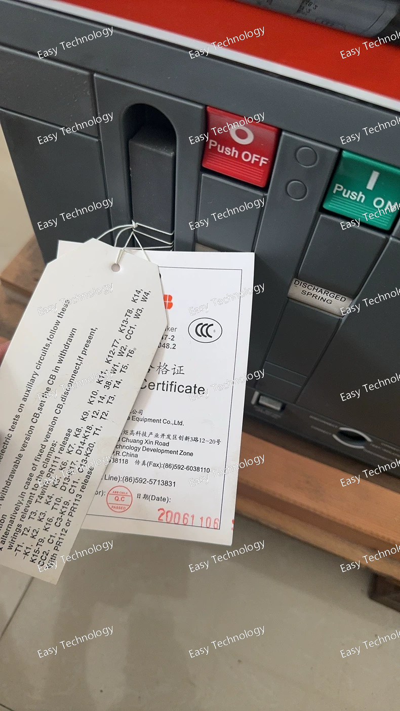
Technical Data: Series: Emax 3 (E3) - Latest generation Variant: N (New Design) - Optimized for sustainability (smaller size, lower losses). Frame Size: E3N frame for high-current ratings. Rated Current (In): 2500 A (Continuous current rating of the breaker's main contacts and conductors). Rated Ultimate Breaking Capacity (Icu): Typically 150 kA at 400/415V AC (Note: The exact Icu for the 2500A E3N frame must be verified from the catalog as it can vary, but it is an extremely high value, e.g., 150kA or 200kA). Number of Poles: 3 Poles (3P). Trip Unit: PR121/LSI - Advanced Digital Trip Unit. Core Protection Functions (Fully Adjustable): L - Overload Protection: Adjustable Ir (0.4 to 1.0 x In) and time delay tr. S - Short-Time Protection: Adjustable Isd (1.5 to 15 x Ir) with selectable time delay curve (I²t ON/OFF) for precise coordination with downstream devices. I - Instantaneous Protection: Adjustable Ii threshold for clearing high-magnitude, non-selective short-circuits. Measurement & Monitoring: The PR121 unit provides real-time measurement of current, voltage, power, and energy. Communication Ready: The PR121 unit is standardly equipped with an embedded Ethernet port (supporting Modbus TCP) for direct, easy integration into Building Management Systems (BMS) or Industrial SCADA without additional gateways. Mounting & Operation: Fixed Horizontal Draw-Out (FHR). Features a stored-energy spring operating mechanism for reliable "Close-Open" (CO) or "Open-Close-Open" (O-CO) duty cycles. Includes an electric spring charging motor and can be equipped with optional closing solenoid and shunt trip. The draw-out mechanism allows for safe racking between CONNECTED, TEST, and DISCONNECTED positions. Auxiliaries: Comes with a standard set of auxiliary contacts for status signaling. Options include additional contacts, undervoltage release, and mechanical key interlocks. Standards Compliance: IEC/EN 60947-2, UL 1066, CSA C22.2 No. 5.
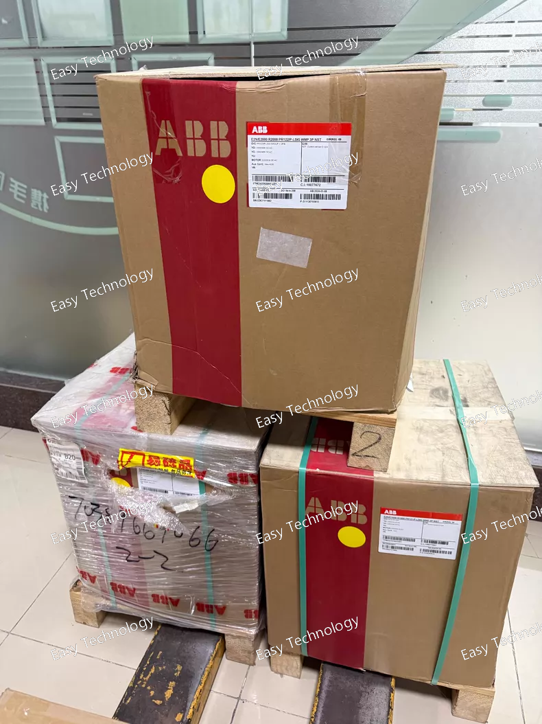
Technical Data: Series: Emax 4 (E4) - Top-tier series for ultra-high current applications. Frame Size: S - Largest physical frame in the Emax 4 range. Rated Current (In): 4000 A (The maximum continuous current rating of the breaker's main bus system and contacts). Rated Ultimate Breaking Capacity (Icu): 150 kA at 400/415V AC *(Note: This is a typical high value for the E4S frame; the definitive Icu/Ics must be verified from the Emax 4 catalog, as it can be 150kA or 200kA depending on the specific certified configuration)*. Number of Poles: 3 Poles (3P - phases L1, L2, L3). Trip Unit: Standard Fixed Protection (Implicit in code). The "P" in the code indicates it is equipped with a "PR332" series basic fixed protection trip unit. This is a non-adjustable, non-communicating electronic unit. Protection: It provides fundamental fixed Long-time (L) and Short-time (S) protection with factory-set thresholds based on the 4000A frame rating. It typically does not include an Instantaneous (I) or Ground-fault (G) function as standard, which is suitable for coordination in high-power selective systems. Mounting & Operation: Fixed Horizontal Draw-Out (WMP). "WMP" is a specific draw-out mechanism code, indicating a robust rack-in/rack-out cradle design. The breaker is fixed to the cradle, and the entire cradle assembly can be moved horizontally into the CONNECTED, TEST, or DISCONNECTED positions. Features a motor-operated stored-energy spring mechanism for reliable high-speed closing and tripping. Equipped with a spring charging motor and a closing solenoid as standard for electrical remote operation. Rated Operational Voltage (Ue): Up to 690 V AC, 50/60 Hz. Control Voltage: Standard auxiliary supply voltage is typically 110-240V AC/DC (specifics defined at order). Standards Compliance: IEC/EN 60947-2, UL 1066, CSA C22.2 No. 5, and other international standards.
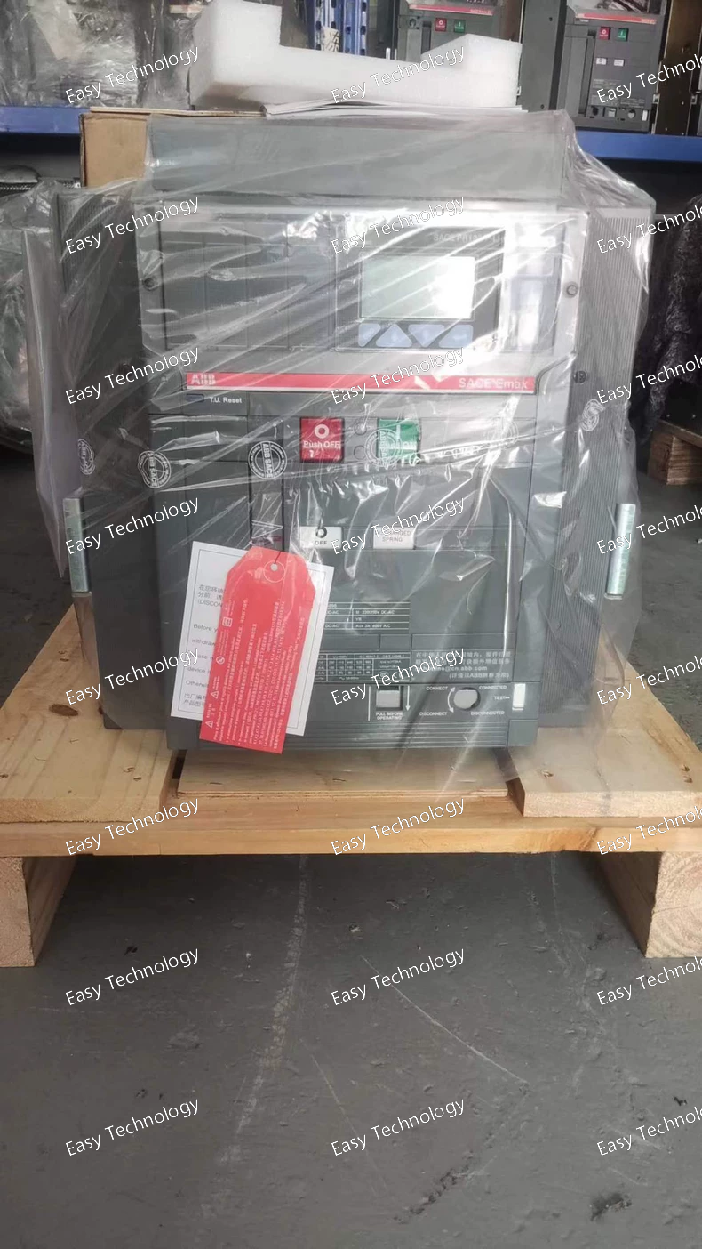
Technical Parameters Parameter Specification Manufacturer ABB Series / Family SACE Emax / E3N Product Type Air Circuit Breaker (ACB) Configuration / Version 3‑pole, withdrawable version (W MP) Rated Uninterrupted Current (In / Iu) 2500 A Number of Poles 3 Rated Operational Voltage Up to 690 V AC Rated Insulation Voltage (Ui) ~1000 V AC Rated Service Short‑Circuit Breaking Capacity (Ics) ~65 kA at 690 V AC Rated Ultimate Short‑Circuit Breaking Capacity (Icu) ~65 kA at 690 V AC Rated Short‑Time Withstand Current (Icw) ~65 kA (1 s / 3 s) Trip Unit Type PR121/P‑LI electronic overcurrent protection Protection Functions Overcurrent / short‑circuit protection via PR121/P‑LI unit Auxiliary Contacts Typically includes auxiliary contacts for breaker position and signaling Terminal Connection Type Withdrawable connection interfaces for switchgear cubicles Mounting Style Switchgear withdrawable frame Standards Compliance IEC / international low‑voltage breaker standards Typical Applications Industrial power distribution, switchgear feeders, main and critical bus protection
Technical Parameters Parameter Specification Manufacturer ABB Product Series SACE Emax / E3H Product Type Air Circuit Breaker (ACB) Configuration Withdrawable version (W MP) Number of Poles 3‑pole (three‑phase) Rated Current (In / Iu) 800 A Rated Operational Voltage (Ue) Up to 690 V AC Rated Insulation Voltage (Ui) 1000 V AC Rated Impulse Withstand Voltage (Uimp) 12 kV Trip Unit PR121/P‑LI electronic overcurrent protection Protection Functions Overload and short‑circuit trip via PR121/P‑LI Rated Service Short‑Circuit Breaking Capacity (Ics) ~85 kA at 690 V AC Rated Ultimate Short‑Circuit Breaking Capacity (Icu) ~100 kA at lower voltages, ~85 kA at 690 V AC Rated Short‑Time Withstand Current (Icw) ~75 kA (1 s) / ~65 kA (3 s) Terminal Style Withdrawable breaker connections for switchgear Standards Compliance IEC low‑voltage circuit breaker standards Typical Application Main distribution protection, feeder breaker, industrial power panels
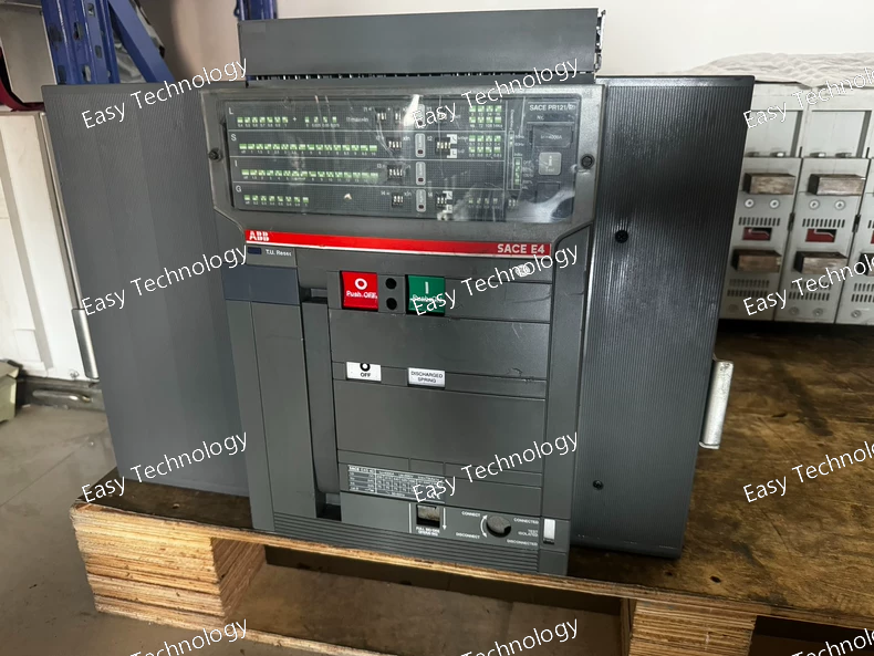
Technical Parameters Parameter Specification Manufacturer ABB Product Series SACE Emax E4S Product Type Air Circuit Breaker (ACB), Withdrawable Version (WMP) Configuration 3‑pole (three‑phase) Rated Continuous Current (Iu / In) 4000 A Rated Operational Voltage (Ue) Up to 690 V AC Rated Insulation Voltage (Ui) 1000 V AC Rated Impulse Withstand Voltage (Uimp) 12 kV Trip Unit Electronic PR121 with LSIG protection Protection Functions Long‑time (L), Short‑time (S), Instantaneous (I), Ground fault (G) Short‑Circuit Performance Level High performance level suitable for industrial networks Rated Service Short‑Circuit Breaking Capacity (Ics) ~75 kA across common low‑voltage levels Rated Ultimate Short‑Circuit Breaking Capacity (Icu) ~75 kA across common low‑voltage levels Rated Short‑Time Withstand (Icw) ~75 kA for 1 s and 3 s Terminal / Connection Type Withdrawable breaker connections for switchgear Mechanical Durability High durability for frequent operations Typical Applications Main distribution protection, switchgear feeder protection in industrial and commercial installations
 TEL: Grace +86 13600179521
  Mail:jilineasyyi@outlook.com
 Q Q:info@hongkongeasy.com
 ADDRESS:Unit 12, 20th Floor, Good View Commercial Centre, 2-16 Garden Street, Mong Kok, Hong Kong
 whats app


