
Industrial Controller
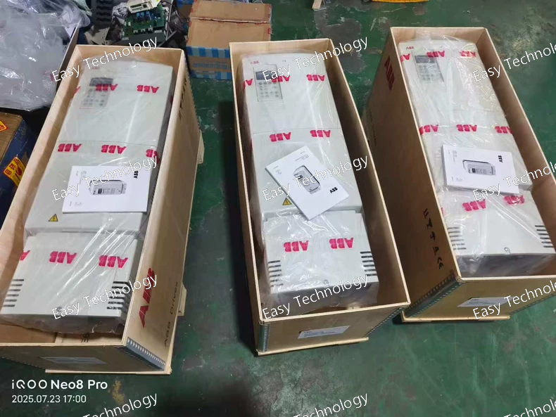
All product are in stock,guaranteed delivery within 3-7 days.


PRODUCT
PICTURE
BRAND
DESCRIBE
STOCK
DOWNLOAD
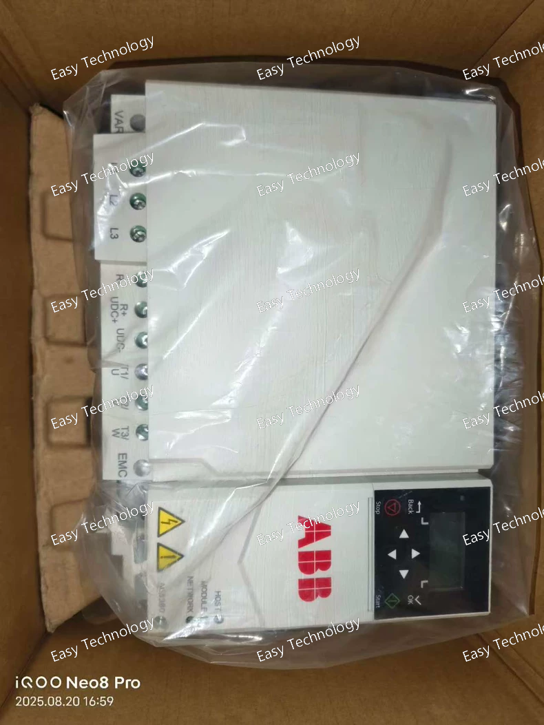
Key Specifications Parameter Category Specification Drive Series/Base Model ACS800-01-0070-5 Rated Output Current 70 A Rated Output Power 45 kW (60 HP) Input Supply Voltage 380 - 500 V AC (-15% / +10%), 3-phase Output Voltage/Phases 3-phase, 0 - Input voltage Enclosure Rating IP21 / UL Type 1 Cooling Method Fan-cooled Control Platform ABB Direct Torque Control (DTC), enabled by +P901. Option +K458 Enhanced Safety Functions Package • Typical Functions: Safe Stop 1 (SS1), Safely Limited Speed (SLS), Safe Brake Control (SBC), in addition to Safe Torque Off (STO). • Safety Level: SIL 3 according to IEC 61800-5-2 / PL e according to ISO 13849-1. • Purpose: Provides certified, integrated safety functions for protecting personnel and preventing hazardous machine motion. Option +P901 Standard Control Program with I/O Extension • Function: Provides essential firmware and I/O hardware. • Includes: Control logic, PID, extensive digital/analog I/O, and relay outputs. Protection Features • Comprehensive motor and drive electrical/thermal protection. • Integrated advanced safety functions via +K458. Application Focus Safety-critical applications: Cranes & Hoists, Robotics, Automated Material Handling, Presses, and machines with hazardous moving parts.
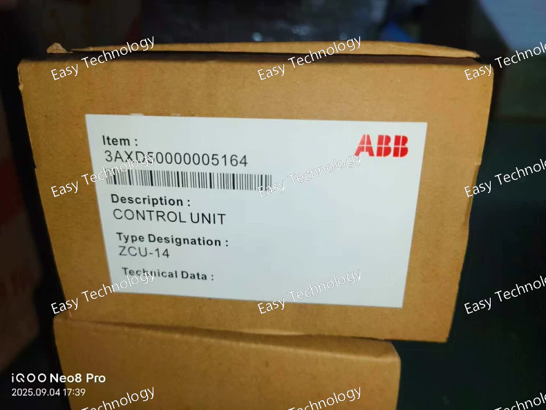
Key Specifications Parameter Category Specification Product Type Zone Control Unit (Safety & Cabinet Control Module) ABB Model ZCU-14 Order Code 3AXD50000005164 Primary Application ACS880 multidrive and other large ABB cabinet drive systems. Key Functions • Safety Interface: Processes safety inputs (e.g., emergency stop, safety door monitors) and controls safety outputs. • Cabinet Cooling Control: Controls and monitors cabinet ventilation fans, including fault detection. • Auxiliary Power Supervision: Monitors voltages of auxiliary power supplies within the zone. • Interlocking Logic: Provides programmable logic for interlocking between drives and external processes. • Diagnostics & Communication: Features LED status indicators and communication interfaces (typically via the drive's main control system). Typical Inputs/Outputs • Digital Inputs: For safety devices, temperature sensors, fan status. • Digital/Relay Outputs: For controlling contactors, fans, and status signals. • Communication: Integrates with the drive system's higher-level controller (e.g., via fiber optic or bus system). Mounting Designed for mounting inside an ACS880 or similar multidrive cabinet. Safety Role A key component in implementing the drive system's overall safety functions (e.g., Safe Torque Off - STO coordination, cabinet access safety).
Key Specifications Parameter Category Specification / Description Product Type Internal Component / Spare Part / Module Assembly ABB Order Code 3ABD00035957-D Associated Systems Likely part of a specific ABB industrial drive platform (e.g., ACS800, ACQ580, or related cabinet systems). Possible Functions Could be one of several specialized parts: • Control or Logic Board: A processing or signal conditioning board. • Power Supply Module: An auxiliary or gate driver power unit. • Communication Interface Board: For specific fieldbus protocols. • Fan Assembly / Cooling Unit: A replacement fan tray. • Capacitor Module: Part of the DC bus or snubber circuit. • I/O or Terminal Board: An extension or replacement I/O module. Physical Form Varies based on function (PCB assembly, mechanical unit with fans, capacitor block, etc.). Critical Note This is a highly specific spare part. Its exact function, compatibility, and technical specifications are defined solely by the host drive system it is designed for.
Key Specifications Parameter Category Specification Drive Series/Model ACS580-01-027A-4 Rated Output Current 27 A Rated Output Power 15 kW (20 HP) Input Supply Voltage 380 - 480 V AC (± 10%), 3-phase Input Supply Phases 3-phase Output Voltage 0 - Input voltage Output Phases 3-phase Enclosure Rating IP21 / UL Type 1 (Standard for -01) Cooling Method Fan-cooled Control Method ABB Direct Torque Control (DTC) Key Standard Features • Energy Optimizer: Automatically minimizes motor and drive losses for maximum energy efficiency. • Intelligent Control Panel (IOP): Plain language, multilingual graphical display for easy setup and monitoring. • Embedded Application Macros: Pre-programmed for common tasks (Pump/Fan, Hand/Auto, etc.). • Built-in EMC Filter (Class A). • Extensive Connectivity: Built-in Modbus RTU (RS-485); optional adapters for PROFINET, EtherNet/IP, PROFIBUS DP, etc. • Advanced PID Controller with sleep/wake and cascade control. • Flying Start and pump-specific functions (dry pump protection, anti-jam). Protection Features • Comprehensive motor thermal protection (I²t, PTC/KTY sensor inputs) • Full electrical protection (short circuit, ground fault, over/undervoltage, overcurrent) • IGBT and heatsink overtemperature protection • Motor stall and underload protection • Coated circuit boards available as an option for harsh environments. Application Focus Pumps, fans, compressors, conveyors, mixers, and other general-purpose industrial applications.
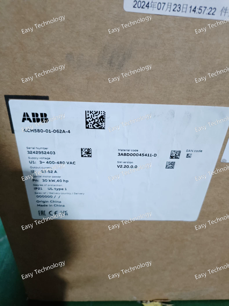
Key Specifications Parameter Category Specification Drive Series/Model ACH580-01-062A-4 Rated Output Current 62 A Rated Output Power 30 kW (40 HP) Input Supply Voltage 380 - 480 V AC (± 10%), 3-phase Input Supply Phases 3-phase Output Voltage 0 - Input voltage Output Phases 3-phase Enclosure Rating IP21 / UL Type 1 (Standard for -01) Cooling Method Fan-cooled Control Method ABB Direct Torque Control (DTC) Key Standard Features • Built-in Connectivity: BACnet MS/TP, Modbus RTU, and Metasys® N2 as standard. • Energy Optimizer: Automatically minimizes motor and drive losses. • Intelligent Control Panel: User-friendly display with application macros. • Built-in EMC Filter (Class A). • Advanced PID Controller with sleep/wake and anti-jam functions. • HVAC-specific functions: Fireman’s override, pump/fan curves. Protection Features • Comprehensive motor thermal protection (I²t, PTC sensor inputs) • Full electrical protection (short circuit, ground fault, over/undervoltage, overcurrent) • IGBT and heatsink overtemperature protection • Motor stall and underload protection • Conformal coated PCB option for harsh environments. Application Focus HVAC systems (air handling units, pumps, fans), light industrial applications, and building automation.
Key Specifications Parameter Category Specification Drive Series/Base Model ACS355-03E-15A6-4 Rated Output Current 15.6 A Rated Output Power 7.5 kW (10 HP) Input Supply Voltage 380 - 480 V AC (± 10%), 3-phase Output Voltage/Phases 3-phase, 0 - Input voltage Enclosure Rating IP20 / UL Open Type (Chassis). Requires installation in a protective cabinet. Control Panel Removable Control Panel (RCP) with backlit LCD. Cooling Method Self-cooled (with internal fan) Control Methods • Scalar Control (V/f) • ABB Direct Torque Control (DTC) Key Standard Features • Removable Control Panel (RCP). • Built-in EMC Filter (Class A). • Application Macros (Factory, Hand/Auto, Pump/Fan). • Built-in PID Controller. • Built-in Modbus RTU (RS-485). Option +B063 Embedded PROFIBUS DP-V1 Adapter Module • Protocol: PROFIBUS DP-V1 (符合 IEC 61158/EN 50170). • Interface: 9-pin D-sub female connector. • Function: Enables integration as a slave device in a PROFIBUS DP network. Supports Process Data Objects (PPO) for fast control and Parameter Channel (PKW) for parameter access. Supports data rates up to 12 Mbps with auto-baud detection. Protection Features • Motor thermal overload protection (I²t) • Short circuit, ground fault, overcurrent, overvoltage protection • IGBT overtemperature protection Application Focus General industrial machinery (Pumps, Fans, Conveyors) within PROFIBUS DP networked automation systems, commonly found with Siemens PLCs.
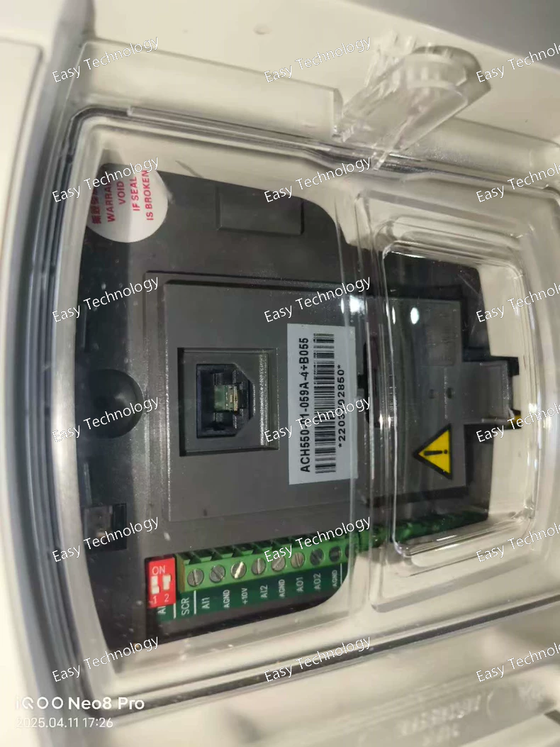
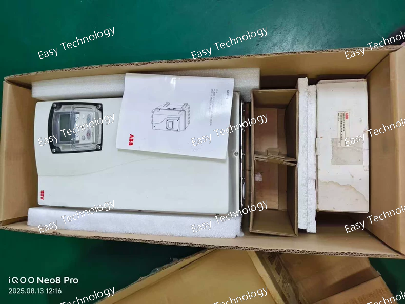
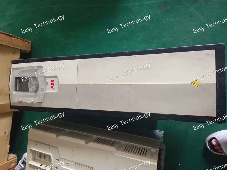
Key Specifications Parameter Category Specification Drive Series/Base Model ACH550-01-059A-4 Rated Output Current 59 A Rated Output Power 30 kW (40 HP) Input Supply Voltage 380 - 480 V AC (± 10%), 3-phase Output Voltage/Phases 3-phase, 0 - Input voltage Enclosure Rating IP21 / UL Type 1 (Indoor, cabinet mounting) Cooling Method Fan-cooled Control Method ABB's Sensorless Flux Control (Magnetizing Flux Control, MFC) for HVAC. Key Standard Features • HVAC-Optimized Software: Advanced PID, multi-pump/fan control logic. • Built-in Building Protocols: BACnet MS/TP and Metasys N2 standard. • Energy Optimizer: Automatically minimizes losses for efficiency. • LCD Keypad with multi-language support. • Extended Safety: Fireman’s Override, smoke control sequences. Option +B055 External Braking Resistor Unit • Function: Provides a path to dissipate regenerative braking energy. • Includes: Internal DC brake chopper and an external, pre-selected braking resistor assembly. • Purpose: Enables controlled deceleration of high-inertia loads (large fans) and prevents drive overvoltage trips during stopping. Protection Features • Comprehensive motor thermal and electrical protection. • Drive overtemperature protection. • Braking resistor thermal protection (via +B055 unit). Application Focus Large Air Handling Units (AHUs), Centrifugal Fans, Large Pump Stations, Industrial Exhaust Systems.
Key Specifications Parameter Category Specification Drive Series/Base Model ACS880-01-240A-5 Rated Output Current 240 A Rated Output Power 132 kW (175 HP) Input Supply Voltage 380 - 500 V AC (-15% / +10%), 3-phase Output Voltage/Phases 3-phase, 0 - Input voltage Enclosure Rating IP21 / UL Type 1 Cooling Method Fan-cooled Control Platform ABB Direct Torque Control (DTC). Fully programmable. Key Standard Features • Intelligent Control Panel (IOP). • Extensive built-in I/O. • Embedded fieldbus connectivity via optional adapters. Option +B056 External Braking Resistor Unit • Function: Provides a dedicated path to dissipate regenerative braking energy as heat. • Includes: Internal brake chopper and an external, pre-selected braking resistor assembly. • Purpose: Enables controlled and rapid deceleration of high-inertia or overhauling loads, preventing drive faults and protecting the DC bus. Protection Features • Comprehensive motor and drive electrical/thermal protection. • Braking resistor thermal protection (via +B056 unit). Application Focus High-power applications with frequent braking: Large fans & blowers, Centrifuges, Cranes & Hoists, Downhill Conveyors, Test Benches.
Key Specifications Parameter Category Specification Drive Series/Model ACS380-040S-032A-4 Rated Output Current 32 A Rated Output Power 15 kW (20 HP) Input Supply Voltage 380 - 480 V AC (± 10%), 3-phase Input Supply Phases 3-phase Output Voltage 0 - Input voltage Output Phases 3-phase Enclosure Rating NEMA 1 / IP20 Open Type (Chassis). Must be installed inside a protective control cabinet. Cooling Method Shaft-through fan cooling Control Method Sensorless Flux Vector Control (Magnetic Flux Control, MFC) Key Standard Features • Material Handling Application Macros: Pre-programmed for common conveyor and lifting tasks. • Dynamic Braking Control: Built-in logic for controlling external brake resistors. • Torque Control & Limits: For tension control and overload prevention. • S-curve Acceleration/Deceleration: For smooth starts and stops. • Removable Control Panel (RCP) with backlit display. • Integrated EMC Filter (Class A). • Built-in Fieldbus: Modbus RTU (RS-485) standard; optional adapters for PROFINET, EtherNet/IP, etc. Protection Features • Motor thermal overload protection (I²t) • Short circuit, ground fault, overcurrent, overvoltage protection • IGBT and heatsink overtemperature protection • Motor stall and underload protection Typical Applications Conveyors (belt, roller, chain), sorting systems, palletizers, and other material transport machinery.
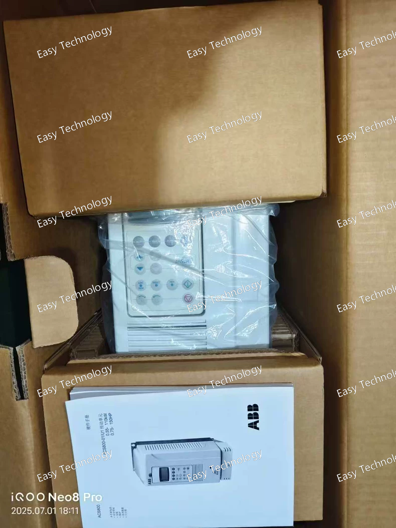
Key Specifications Parameter Category Specification Drive Series/Base Model ACS800-01-0020-5 Rated Output Current 20 A Rated Output Power 7.5 kW (10 HP) Input Supply Voltage 380 - 500 V AC (-15% / +10%), 3-phase Output Voltage/Phases 3-phase, 0 - Input voltage Enclosure Rating IP21 / UL Type 1 Cooling Method Fan-cooled Control Platform ABB Direct Torque Control (DTC). Fully programmable. Key Standard Features • Intelligent Control Panel (IOP). • Extensive built-in I/O. • Standard control functionalities. Option +E200 Embedded PROFINET IO Controller/Device Adapter • Protocol: PROFINET IO (Conformance Class B/C). • Role: Supports Controller (for other I/O) and Device (to a higher-level PLC) roles simultaneously. • Ports: 2 x RJ45 (100 Mbps), integrated switch. • Key Features: Supports IRT (Isochronous Real-Time), MRP (Media Redundancy Protocol), and PROFIsafe (for safety over PROFINET). Protection Features • Comprehensive motor and drive electrical/thermal protection. Application Focus Industrial automation systems within PROFINET networks, such as packaging machinery, conveyors, and automated assembly lines, particularly those integrated with Siemens PLCs.
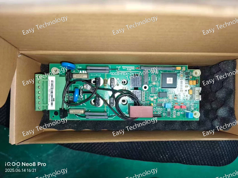
Key Specifications Parameter Category Specification / Description Product Type Internal Electronic Module / Circuit Board (Spare Part) ABB Order Code 3ADT311500R0001 Associated Systems Likely part of an ABB industrial drive (e.g., ACS800, ACQ580 series) or its control cabinet accessories. Typical Function Could be one of several specialized internal functions: • Auxiliary Power Supply Board: Provides regulated low-voltage power to control circuits. • Communication Interface Board: Handles specific fieldbus protocols (e.g., PROFIBUS, DeviceNet). • I/O Extension or Terminal Board: Provides additional input/output channels. • Gate Driver or Signal Conditioning Board: Interfaces between the main control unit and power semiconductors. Physical Form Printed Circuit Board (PCB) assembly with specific connectors and components. Critical Note This is a highly specific spare part. Its exact function, compatibility, and electrical specifications are defined solely by the host system it is designed for.
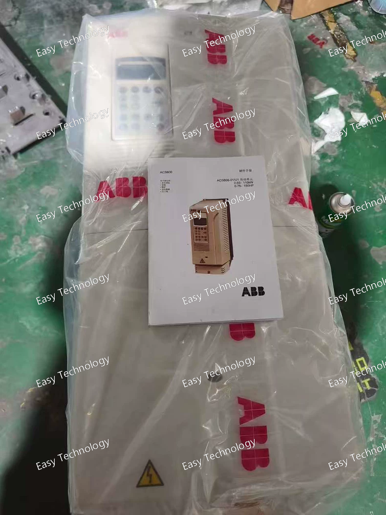
Key Specifications Parameter Category Specification Drive Series/Base Model ACS800-01-0120-5 Rated Output Current 120 A Rated Output Power 75 kW (100 HP) (at 400V) Input Supply Voltage 380 - 500 V AC (-15% / +10%), 3-phase Output Voltage/Phases 3-phase, 0 - Input voltage Enclosure Rating IP21 / UL Type 1 Cooling Method Fan-cooled Control Platform ABB Direct Torque Control (DTC), enabled by +P901. Option +E200 Embedded PROFINET IO Adapter • Protocol: PROFINET IO (Conformance Class B/C). • Role: Controller and Device. • Ports: 2 x RJ45 (100 Mbps). • Features: Supports IRT, MRP, PROFIsafe. Option +L503 Encoder Interface Module • Feedback Types: Sin/Cos (1 Vpp), TTL/HTL, Resolver. • Purpose: Enables high-performance closed-loop vector control for precise speed regulation and basic positioning. Option +P901 Standard Control Program with I/O Extension • Function: Provides essential firmware and I/O hardware. • Includes: Control logic, PID, extensive digital/analog I/O, and relay outputs. Protection Features • Comprehensive motor and drive electrical/thermal protection. Application Focus Complex automation: Multi-motor conveyors, printing presses, extruders, test benches requiring PROFINET integration and encoder feedback.
 TEL: Grace +86 13600179521
  Mail: info@hongkongeasy.com jilineasyyi@outlook.com
 Q Q:615739355
 ADDRESS:Unit 12, 20th Floor, Good View Commercial Centre, 2-16 Garden Street, Mong Kok, Hong Kong
 whats app


