
Industrial Controller
All product are in stock,guaranteed delivery within 3-7 days.


PRODUCT
PICTURE
BRAND
DESCRIBE
STOCK
DOWNLOAD
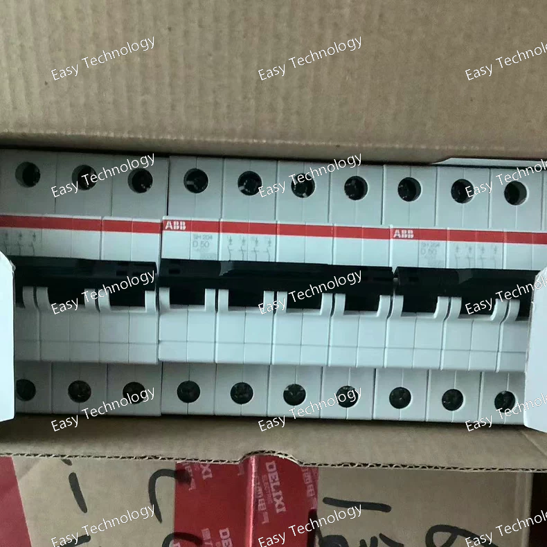
Technical Specifications Parameter Specification Part / Model SH204‑D10 Series / Family ABB S‑200 / System Pro M Compact miniature circuit breaker Configuration 4‑pole (4P) Rated Current (In) 10 A Trip Curve / Characteristic D (high inrush tolerance) Rated Operational Voltage Up to ~480 V AC / 277 V AC (typical for UL/IEC) Rated Insulation Voltage (Ui) ~440 V AC Rated Impulse Withstand Voltage (Uimp) ~4 kV Frequency 50/60 Hz Mounting DIN‑rail (TH35) Terminal Type Screw terminals Type of Protection Thermal trip for overload + electromechanical trip for short circuit Short‑Circuit Breaking Capacity ~6 kA at 230/400 V AC Standards Compliance IEC/EN 60898‑1, IEC/EN 60947‑2, UL 1077, CSA Pollution Degree 2 Overvoltage Category III Degree of Protection IP20 Ambient Operating Temperature –25 °C to +55 °C Connectable Conductor (solid) ~0.75 – 25 mm² Connectable Conductor (stranded) ~0.75 – 16 mm²
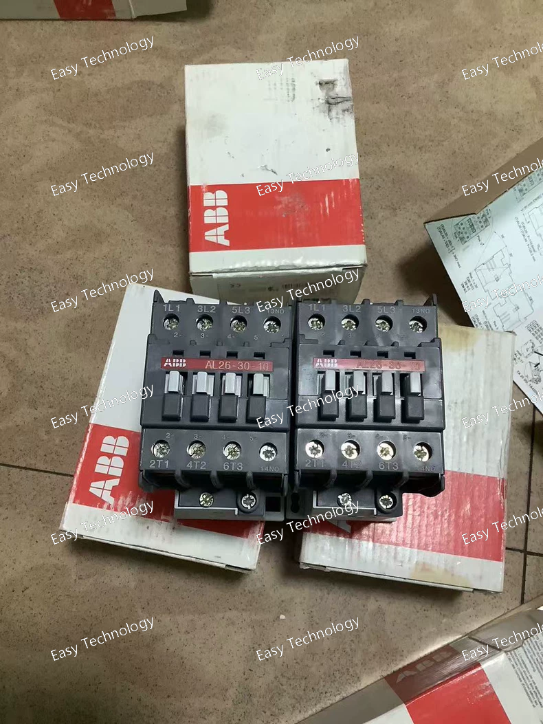
Technical Specifications Parameter Specification Part Number / Model 1SBL243001R8110 Product Type Three‑Pole DC Power Contactor Series / Family AL26 Series Control / Coil Voltage 24 V DC Number of Main Contacts 3 Normally Open (3 NO) Auxiliary Contacts 1 Normally Open (1 NO) Rated Operational Voltage (Main Circuit) Up to 690 V AC Rated Operational Current AC‑1 (Ie) Up to ~45 A at 690 V AC (free‑air thermal current) Rated Operational Current AC‑3 (Ie) ~26 A at 220–500 V AC typical Rated Operational Power AC‑3 (Pe) ~6.5 kW at 220–240 V AC; ~11 kW at 380–440 V AC; up to ~15 kW at 440–500 V AC Rated Insulation Voltage (Ui) 1000 V Rated Impulse Withstand Voltage (Uimp) 8 kV Rated Breaking Capacity (AC‑3) 8 × Ie Coil Consumption Low‑power DC coil (~3.5 W hold and pull‑in) Mechanical Switching Frequency Up to ~3600 cycles/hour Electrical Switching Frequency AC‑1: ~600 cycles/hour; AC‑3: ~1200 cycles/hour Control Frequency 50 / 60 Hz DC control Terminal Type Screw terminals Operating Temperature Range ~‑40 °C to +55 °C Mounting Panel / DIN‑rail compatible Weight ~0.75 kg Typical Dimensions ~54 mm (W) × ~110 mm (D) × ~90 mm (H)
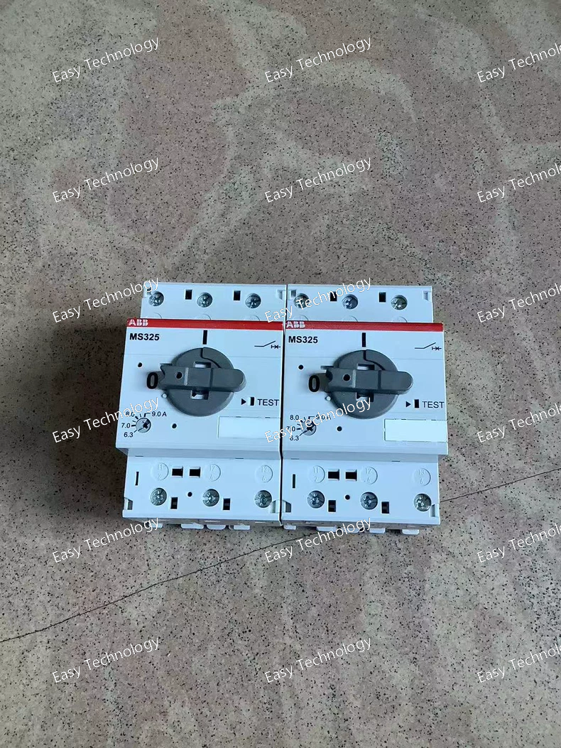
Technical Specifications Parameter Specification Product / Model ABB MS325‑9 Manual Motor Starter Part Type Manual Motor Starter / Motor Protection Device Series MS325 Rated Operational Current (Ie) 9 A Setting Range 6.3 A – 9 A (adjustable) Number of Poles 3 poles Rated Operational Voltage Up to 690 V AC main circuit (also compatible up to 440 V DC) Rated Service Short‑Circuit Breaking Capacity (Ics) 100 kA at 400 V AC Trip Class Class 10A (thermal overload) Control / Handle Rotary handle (ON/OFF) with clear position indication Disconnect Function Built‑in disconnect capability Phase Failure Sensitivity Yes Trip‑Free Mechanism Yes Mounting Type DIN‑rail or panel mount Enclosure Protection IP20 Connection Type Screw terminals Operating Frequency 50/60 Hz Operating Temperature Range Approximately −25 °C to +50 °C Dimensions ~54 mm width × 75.5 mm depth × 87.5 mm height Typical Motor Power (AC‑3) ~4 kW at 400 V AC Accessories Available Auxiliary contacts, signalling contacts, undervoltage/shunt releases, bus bars, locking devices
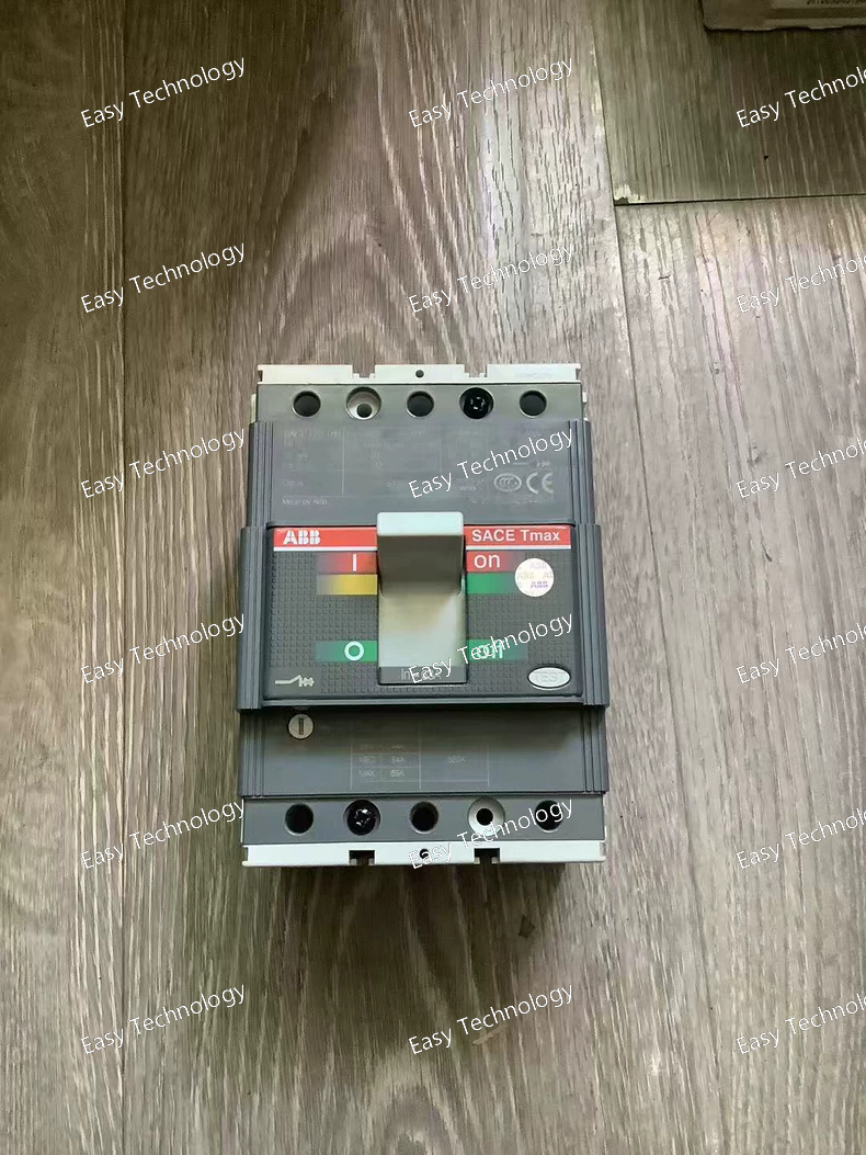
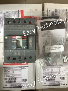
Technical Specifications Parameter Specification Part Number / Model 1SDA051000R1 Product Type Molded Case Circuit Breaker (MCCB) Series / Family TMAX T2S 160 Trip Unit Thermo‑magnetic (TMD) Poles 3‑pole (3P) Thermal Setting Range Adjustable (63 – 630 A) Rated Current (In) Typically set at 63 A (user adjustable within range) Rated Uninterrupted Current (Iu) 160 A (frame rating) Rated Operational Voltage (Ue) Up to 690 V AC Rated Insulation Voltage (Ui) ~1000 V Rated Impulse Withstand Voltage (Uimp) ~8 kV Rated Ultimate Short‑Circuit Breaking Capacity (Icu) Up to ~50 kA (at lower AC voltages) and ~7 kA at 690 V AC Rated Service Short‑Circuit Breaking Capacity (Ics) Similar to Icu at common system voltages Terminal Type Front bolt terminals Mounting Fixed installation Standards Compliance IEC 60947‑2 Mechanical Durability High mechanical endurance (~25,000 operations typical) Electrical Endurance Thousands of electrical operations Dimensions (approx.) Width ~90 mm × Height ~130 mm × Depth ~70 mm Weight (approx.) ~1.1 kg
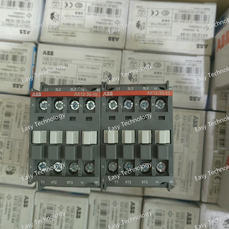
Technical Specifications Parameter Specification Part / Model AX12‑30‑10‑84 (1SBL911074R8410) Product Type Three‑Pole AC Contactor Series / Family AX series Control Coil Voltage 110 V AC (50 Hz) / 110–120 V AC (60 Hz) Number of Main Contacts 3 Normally Open (3 NO) Auxiliary Contacts 1 (depends on configuration: NO or NC) Rated Operational Voltage (Main Circuit) Up to 690 V AC Rated Operational Current (AC‑1) ~25 A (400 V AC typical) Rated Operational Current (AC‑3) ~12 A (400 V AC typical) Rated Motor Power (AC‑3) ~5.5 kW (400 V AC) Rated Insulation Voltage (Ui) 690 V Rated Impulse Withstand Voltage (Uimp) ~6–8 kV Control Frequency 50/60 Hz Terminal Type Screw terminals Short‑Time Withstand Current (Icw) ~280 A (typical 1 s, cold) Mechanical Switching Frequency ~3600 cycles/hour Electrical Switching Frequency AC‑1 ~600 cycles/hour; AC‑3 ~1200 cycles/hour Mounting Panel or DIN‑rail compatible Protection / Housing IP20 (typical) Dimensions (approx.) Width ~44 mm Weight (approx.) ~0.32 kg
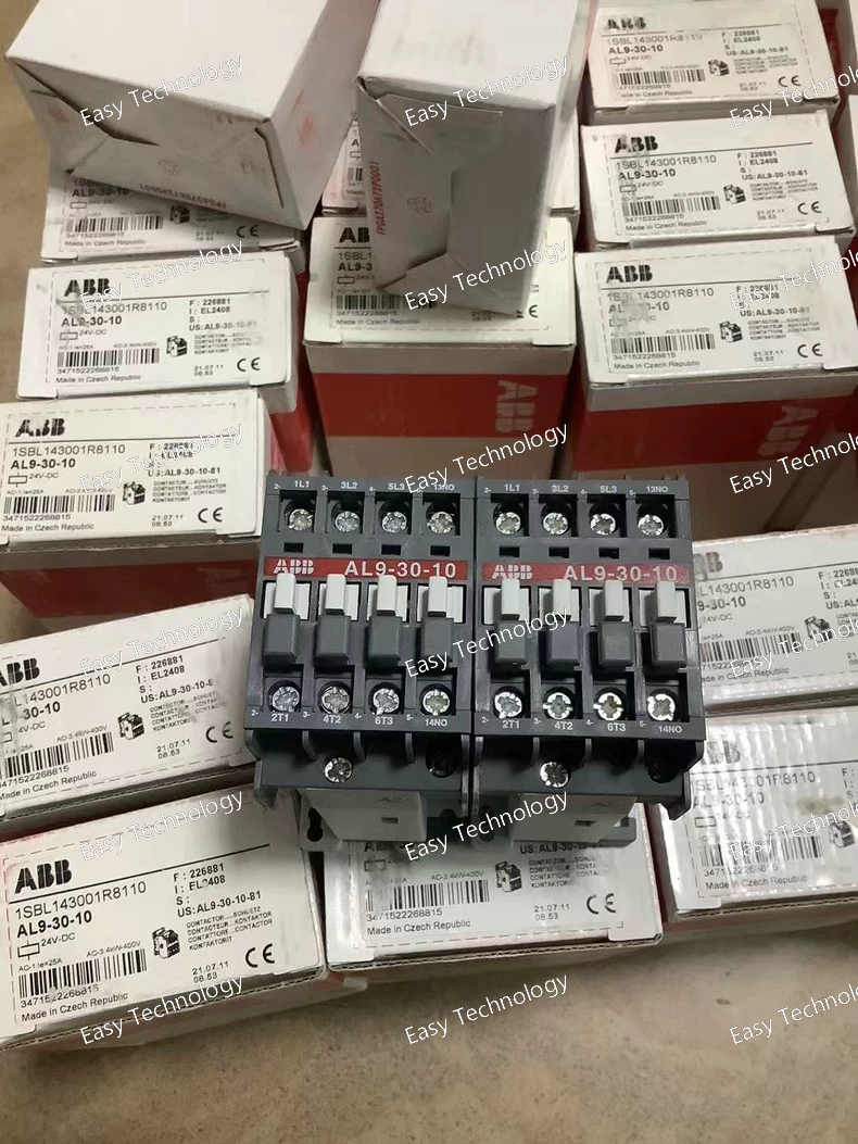
Technical Specifications Parameter Specification Part Number / Model 1SBL143001R8110 Product Type Power Contactor Series / Family AL9 series Control / Coil Voltage 24 V DC Rated Operational Voltage (Main Circuit) Up to 690 V AC Number of Poles 3 main poles (3P) Main Contacts 3 Normally Open (3 NO) Auxiliary Contacts 1 Normally Open (1 NO) Rated Operational Current (AC‑3) 9 A (typical motor control duty) Rated Operational Current (AC‑1) ~25 A (general load) Rated Operational Power (AC‑3) ~2.2 kW at 220–240 V AC; ~4 kW at 380–400 V AC; ~5.5 kW at 500–690 V AC Rated Insulation Voltage (Ui) 1000 V Rated Impulse Withstand Voltage (Uimp) 8 kV Control Circuit Type DC operated with solid core magnetic coil Auxiliary / Add‑on Blocks Front and side‑mounted auxiliary contact blocks available Mounting Panel / block contactor mount Terminal Type Screw terminals Ambient Operating Temperature –40 °C to +55 °C Protection Degree IP20 Weight ~0.52 kg Dimensions ~44 × 78 × 97 mm (W × H × D)
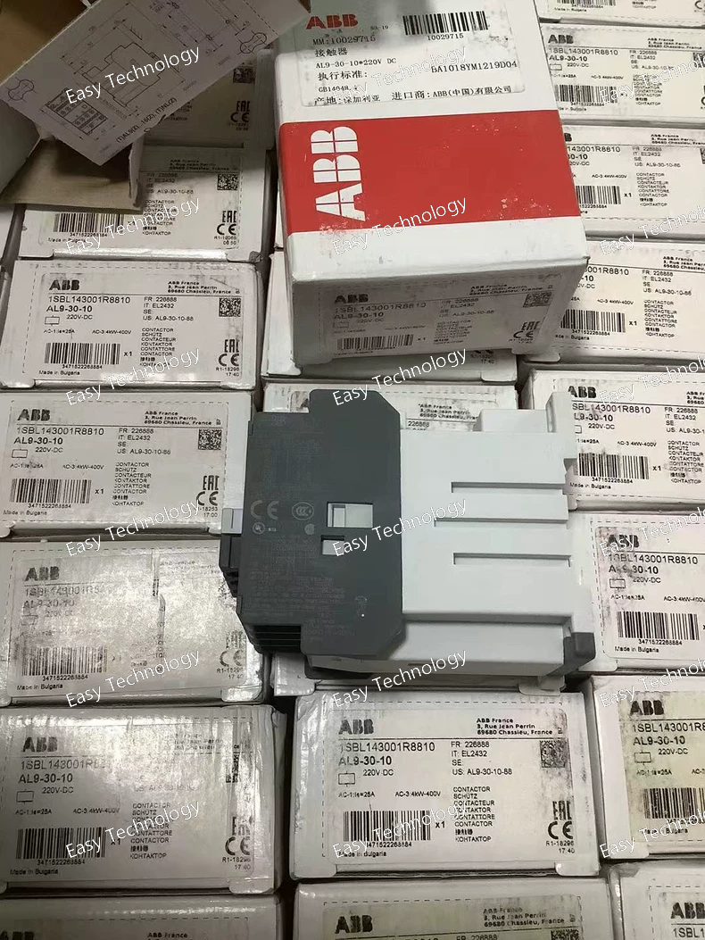
Technical Specifications Parameter Specification Part / Model ABB AL9‑30‑10 220 V DC Contactor (1SBL143001R8810) Product Type 3‑Pole Power Contactor Series / Family AL9 Series Control / Coil Voltage 220 V DC Number of Main Contacts 3 Normally‑Open (3 NO) Auxiliary Contacts 1 Normally‑Open (1 NO) Rated Operational Voltage (Main Circuit) Up to 690 V AC Rated Operational Current AC‑1 ~25 A Rated Operational Current AC‑3 ~9 A Rated Operational Power AC‑3 ~4 kW (at 400 V AC) Rated Insulation Voltage Up to 690 V (IEC standards) Terminal Type Screw terminals Control Frequency DC coil operation Mounting Panel / DIN rail compatible Application Motor control, load switching, general power circuits
Technical Specifications Parameter Specification Part Number / Model 1SDA068057R1 Product Type Molded Case Circuit Breaker (MCCB) Series / Family SACE Tmax XT3N Trip Unit Type Thermo‑magnetic (TMD), adjustable short‑circuit range 160–1600 A Number of Poles 3 poles (3P) Rated Current (In) 160 A Overload Setting Range ~112–160 A Instantaneous Trip Setting (Short‑Circuit) 1600 A (fixed) Rated Operational Voltage (Ue) Up to 690 V AC / 500 V DC Rated Insulation Voltage (Ui) ~800–1000 V Rated Impulse Withstand Voltage (Uimp) 8 kV Rated Ultimate Short‑Circuit Breaking Capacity (Icu) ~36 kA at 400 V AC Rated Service Short‑Circuit Breaking Capacity (Ics) Similar to Icu at common voltages Terminal Connection Front bolt terminals Connection Capacity Cable/busbar compatible Mechanical Durability ~25,000 operations Electrical Endurance ~8,000 operations Degree of Protection IP20 Standards Compliance IEC 60947‑2 Mounting Fixed installation with front access
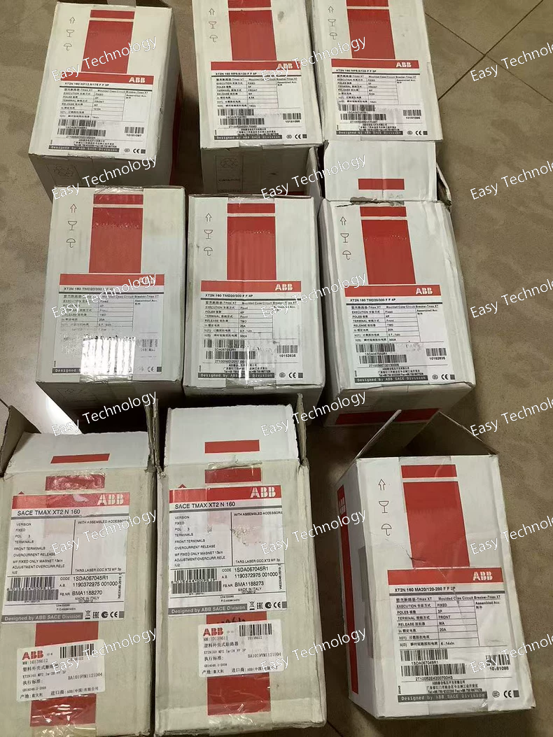
Technical Specifications Parameter Specification Part Number / Model 1SDA067032R1 Product Molded Case Circuit Breaker (MCCB) Series / Family Tmax XT2N Trip Unit Type Thermomagnetic (TMD), adjustable 20–300 A Number of Poles 4 Poles (4P) Rated Operational Current (In) 20 A (trip setting) Rated Uninterrupted Current (Iu) 160 A Adjustment Range (Thermal / Magnetic) 14–20 A thermal; magnetic up to 300 A Rated Operational Voltage (Ue) up to 690 V AC / 500 V DC Rated Insulation Voltage (Ui) 1000 V Rated Impulse Withstand Voltage (Uimp) 8 kV Short‑Circuit Breaking Capacity (Icu) Up to 65 kA at lower AC voltages; 36 kA at 380–440 V AC; 10 kA at 690 V AC Rated Service Breaking Capacity (Ics) Same as Icu ratings Terminal Type Front bolt terminals Connection Capacity Cable/busbar compatible (e.g., 32.5–100 mm²) Mechanical Durability ~25,000 operations Electrical Endurance ~8,000 operations Degree of Protection IP20 Standards Compliance IEC 60947‑2 Typical Weight ~1.4–1.6 kg Typical Width ~120 mm
Technical Specifications Parameter Specification Part Number / Model 1SDA067049R1 Product Type Molded Case Circuit Breaker (MCCB) Series / Family Tmax XT2N Trip Unit / Release Type Magnetic only (MA / MF) Number of Poles 3 poles (3P) Rated Current (In) 20 A Frame / Uninterrupted Current (Iu) 160 A Adjustable Magnetic Trip Range (Ii / Im) 120 A … 280 A Rated Operational Voltage (Ue) Up to 690 V AC / 500 V DC Rated Insulation Voltage (Ui) 1000 V Rated Impulse Withstand Voltage (Uimp) 8 kV Rated Service Short‑Circuit Breaking Capacity (Ics) Up to 65 kA at lower AC voltages; 36 kA at 380–440 V AC; 10 kA at 690 V AC Rated Ultimate Short‑Circuit Breaking Capacity (Icu) Same as Ics across rated voltages Terminal Type Front bolt terminals Connection Capacity Busbar/cable compatible (e.g., 32.5–100 mm²) Mechanical Durability ~25,000 operations Electrical Endurance ~8,000 operations Standards Compliance IEC 60947‑2 Weight (approx.) ~1.1 kg Dimensions (approx.) Width ~90 mm × Height ~130 mm × Depth ~82.5 mm
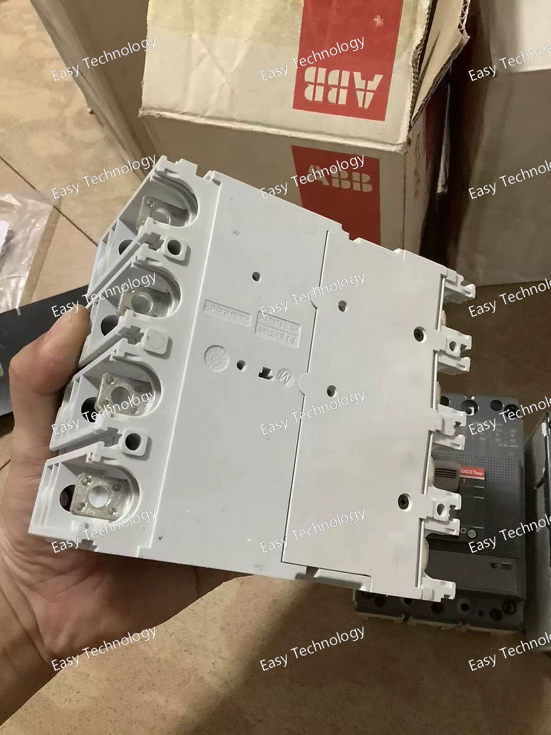
Technical Specifications Parameter Specification Part Number / Model 1SDA067048R1 Product Type Molded Case Circuit Breaker (MCCB) Series / Family Tmax XT2N Trip Unit / Release Magnetic (MF) Number of Poles 3 poles (3P) Rated Current (In) 12.5 A Rated Uninterrupted Current (Iu) 160 A Rated Instantaneous Short‑Circuit Setting (Ii) 175 A Rated Operational Voltage (Ue) Up to 690 V AC / 500 V DC Rated Insulation Voltage (Ui) 1000 V Rated Impulse Withstand Voltage (Uimp) 8 kV Rated Service Short‑Circuit Breaking Capacity (Ics) Up to 65 kA at lower AC voltages / 36 kA at 380–440 V AC / 10 kA at 690 V AC Breaking Capacity (Icu) Same as Ics across rated voltages Terminal Type Front terminals (bolt) Connection Capacity Busbar/cable compatible (typically 32.5–100 mm²) Mechanical Durability ~25,000 operations Electrical Endurance ~8,000 operations Standards Compliance IEC 60947‑2 Mounting Fixed installation Typical Dimensions Width ~90 mm; Height ~130 mm; Depth ~82.5 mm Weight (approx.) ~1.1–1.2 kg
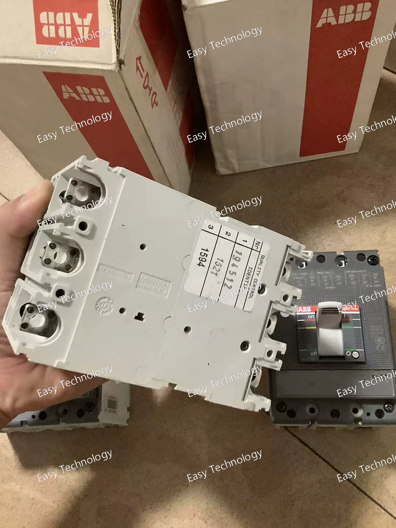
Technical Specifications Parameter Specification Part Number / Model 1SDA067047R1 Product Type Molded Case Circuit Breaker (MCCB) Series / Family Tmax XT2N Trip Mechanism / Release Type Magnetic (MF) Number of Poles 3 (3P) Rated Current (In) 8.5 A Rated Frame Current (Iu) 160 A Adjustment Range of Magnetic Release (Im) 120 A Rated Operational Voltage (Ue) up to 690 V AC / 500 V DC Rated Insulation Voltage (Ui) 1000 V Rated Impulse Withstand Voltage (Uimp) 8 kV Rated Short‑Circuit Breaking Capacity (Icu) 36 kA at 400 V AC Rated Service Short‑Circuit Breaking Capacity (Ics) up to 36 kA Terminal Type Front bolt terminals Connection Capacity Cable/busbar connections (32.5–100 mm²) Mechanical Durability ~25,000 operations Electrical Endurance ~8,000 operations Standards Compliance IEC 60947‑2 Degree of Protection IP20 Weight ~1.2–1.4 kg Dimensions (approx.) Width ~90 mm Typical Applications Protection of three‑phase feeders Short‑circuit and overcurrent protection in industrial panels Power distribution systems in industrial and commercial buildings Motor feeder protection and general circuit protection
 TEL: Grace +86 13600179521
  Mail: info@hongkongeasy.com jilineasyyi@outlook.com
 Q Q:615739355
 ADDRESS:Unit 12, 20th Floor, Good View Commercial Centre, 2-16 Garden Street, Mong Kok, Hong Kong
 whats app


