
Industrial Controller
All product are in stock,guaranteed delivery within 3-7 days.


PRODUCT
PICTURE
BRAND
DESCRIBE
STOCK
DOWNLOAD
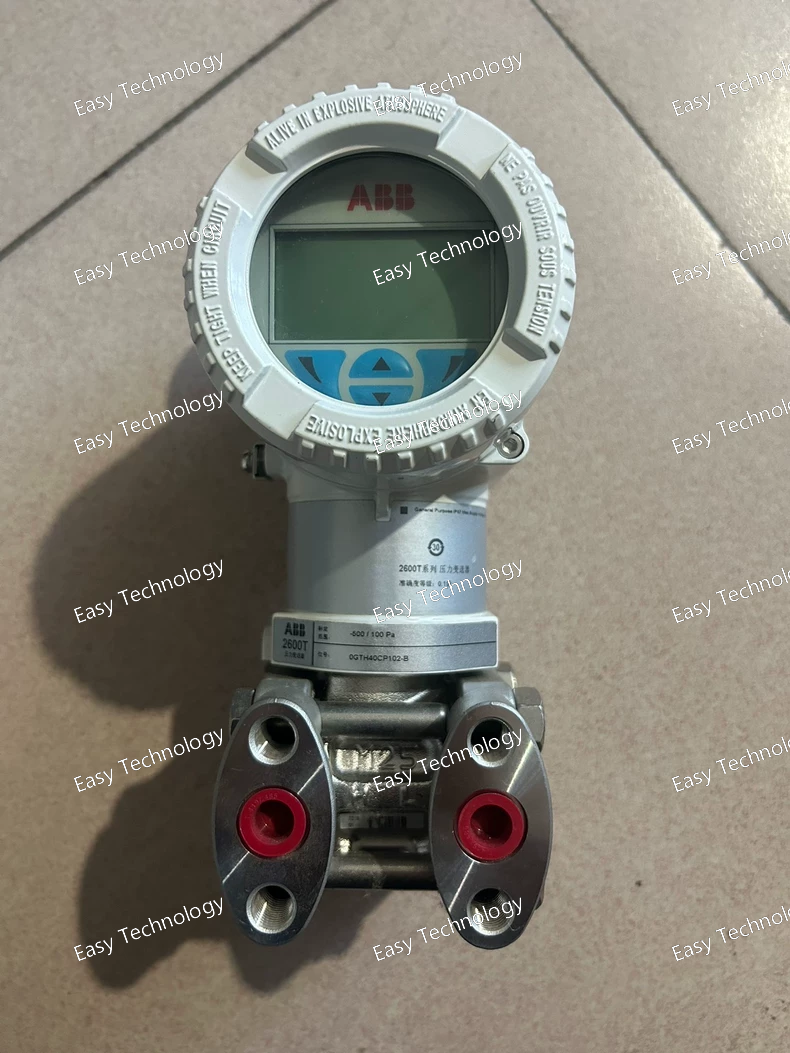
Parameters Category Parameter Specification / Interpretation for 266DSH BSHA1B2L1TB General Model Series 2600T Series (DST - Differential Pressure Smart Transmitter) Type Smart dP Transmitter with Local Operator Interface Output 4-20 mA DC, Two-wire, HART Protocol. Measurement Performance Measured Variable Differential Pressure (dP) Calibrated Span (BSHA1) Defined by core code. Example: 0 to 40 kPa (0.4 bar). Must be verified from official datasheet. Reference Accuracy ±0.075% of calibrated span (Typical). Long-Term Stability ±0.1% of URL per year. Turndown Ratio Up to 100:1 (Software configurable). User Interface Local Display (L1) Backlit LCD. Local Controls Push Buttons (for configuration and navigation). Electrical Supply Voltage 10.5 to 45 V DC (Two-wire). Load Limit R_L ≤ (Vs - 10.5V) / 0.022 A (Ω). Communication HART Protocol (Bell 202 FSK). Process Connections & Materials Wetted Parts (BSH) Isolating Diaphragms & Process Connections: 316L Stainless Steel (Standard). Fill Fluid Silicone Oil (Standard) or Inert Fluorocarbon (for O2/aggressive service). Pressure Ports 1/4" NPT or G1/2" female (Common). Static Pressure Rating Up to 16 MPa (2320 psi). Mechanical & Environmental Housing Stainless Steel, Flameproof (Ex d) enclosure. Protection Degree IP66 / IP67 / NEMA 4X. Process Temperature -40°C to +120°C (Standard fill fluid). Ambient Temperature -40°C to +85°C. Certifications & Safety Explosion Protection (TB) ATEX / IECEx: Ex d IIC T4/T6 Gb (Flameproof) & Ex ia IIC T4/T6 Ga (Intrinsic Safety) - Dual Certification. Functional Safety SIL 2/3 capable.
Parameters Category Parameter Specification / Interpretation for 266DSHBSHA1B2 V1L1B1TB General Model Series 2600T Series (DST - Differential Pressure Smart Transmitter) Type Smart dP Transmitter with Steam Flow Option & Local Display Output 4-20 mA DC, Two-wire, HART Protocol. Measurement & Computation Primary Measurement Differential Pressure (dP) Calibrated dP Span (BSHA1) Defined by core code. Example: 0 to 100 kPa (1 bar). Must verify from datasheet. Reference Accuracy (dP) ±0.075% of calibrated span (Typical). Steam Flow Option (V1) On-board IAPWS-IF97 steam properties. Output can be configured as Mass Flow Rate (e.g., kg/h, lb/h). Output Characterization (B1) Selectable: Linear (for pressure/level) or Square Root (for flow with primary element). With V1, output is linearized flow. Options & Features Local Display (L1) LCD Local Indicator. Certification Package (TB) ATEX / IECEx: Ex d IIC T4/T6 Gb (Flameproof) & Ex ia IIC T4/T6 Ga (Intrinsic Safety) certificates. Electrical Supply Voltage 10.5 to 45 V DC (Two-wire). Communication HART Protocol. Process Connections & Materials Wetted Parts (BSH) Isolating Diaphragms: 316L SST or similar alloy. Fill Fluid Silicone Oil or Inert Fluorocarbon. Pressure Ports 1/4" NPT or G1/2" female. Mechanical & Environmental Housing Stainless Steel, Flameproof. Protection Degree IP66 / IP67 / NEMA 4X. Process Temperature -40°C to +120°C. Ambient Temperature -40°C to +85°C.
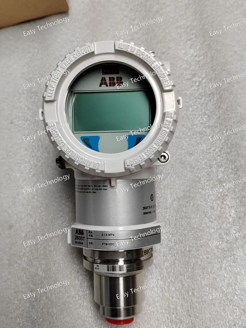
Parameters Category Parameter Specification / Interpretation for 266HDHHRMA7+LSTB General Model Series 2600T Series (PGT - Pressure Gauge/Absolute Transmitter) Type Smart Absolute Pressure Transmitter with Local Operator Interface Output 4-20 mA DC, Two-wire, HART 7 Digital. Measurement Performance Measured Variable Absolute Pressure Calibrated Span (HDHHRMA7) Defined by core code. Example: 0 to 400 kPa abs (4 bar abs). Must be verified from official datasheet. Reference Accuracy ±0.055% to ±0.075% of calibrated span (Typical for this performance grade). Long-Term Stability ±0.1% of URL per year. Options & Features (+LSTB) Local Operator Interface Backlit Graphical LCD Display. Infrared (IR) Push Buttons (for Ex ia certified local operation). Certification Package ATEX / IECEx: Ex d IIC T6 Gb (Flameproof) & Ex ia IIC T6 Ga (Intrinsic Safety) - Dual Certification. Electrical Supply Voltage 10.5 to 45 V DC (Two-wire). Communication HART 7 Protocol. Process Connections & Materials Process Connection 1/2" NPT female or G1/2" (typical). Wetted Parts 316L Stainless Steel (standard). Other alloys (Hastelloy, Monel) available with different suffix. Mechanical & Environmental Housing Stainless Steel, Flameproof (Ex d) enclosure. Protection Degree IP66 / IP67 / NEMA 4X. Process Temperature -40°C to +120°C (standard fill fluid). Ambient Temperature -40°C to +85°C.
Parameters Category Parameter Specification / Interpretation for 266HSHQKBA7 General Model Series 2600T Series (FMT - Flow Multivariable Transmitter) Type Smart Multi-Variable Flow Transmitter with Corrosion-Resistant Wetted Parts Measured Variables Differential Pressure (ΔP), Static Pressure (Ps), Temperature (T). Measurement Performance ΔP Span Range Defined by suffix "QKBA7". Indicates a specific calibrated span. Example: 0 to 100 kPa (1 bar). Must verify from datasheet. Static Pressure (Ps) Range High Range, e.g., 0 to 16 MPa (2320 psi). Temperature (T) Range Integrated RTD: -40°C to +125°C. Reference Accuracy (Flow) ±0.15% of reading (typical for compensated flow). Long-Term Stability ±0.1% of URL per year. Computation & Output Calculated Variable Mass Flow or Volumetric Flow (density-compensated). Fluid Database Pre-loaded with common gas & steam properties. Primary Element Support Orifice, Venturi, Nozzle, Wedge, Pitot Tube (per ISO/AGA). Analog Output 4-20 mA, two-wire. Primary Variable = Flow. Digital Output HART 7 Protocol. Process Connections & Materials (Key Feature) Wetted Parts (QK) Isolating Diaphragms: Hastelloy C-276 or equivalent nickel-based alloy. Process Flanges/Connections: 316L SST or matching alloy. Fill Fluid Silicone oil or Inert Fluorocarbon (specify for O2 service). Pressure Ports 1/4" NPT or G1/2" female (typically in 316L SST). Mechanical & Environmental Housing Stainless Steel. Protection Degree IP66 / IP67 / NEMA 4X. Process Temperature -40°C to +120°C (wetted parts). Ambient Temperature -40°C to +85°C. Certifications Explosion Protection Base design supports ATEX/IECEx: Ex ia IIC T4/T6 Ga & Ex d IIC T4/T6 Gb (as an ordered option). Material Certs 3.1 Material Certificate typically provided for the Hastelloy wetted parts.
Parameters Category Parameter Specification / Interpretation for 266HSHMSBA7 General Model Series 2600T Series (FMT - Flow Multivariable Transmitter) Type Smart Multi-Variable Flow Transmitter (4-20mA HART 7) Measured Variables Differential Pressure (ΔP), Static Pressure (Ps), Temperature (T). Measurement Performance ΔP Span Range Defined by suffix "MSBA7". Indicates a specific calibrated span. Example: 0 to 25 kPa (0.25 bar). Must verify from datasheet. Static Pressure (Ps) Range High Range, e.g., 0 to 16 MPa (2320 psi). Temperature (T) Range Integrated RTD: -40°C to +125°C. Reference Accuracy (Flow) ±0.15% of reading (typical for density-compensated flow). Long-Term Stability ±0.1% of URL per year. Computation & Output Calculated Variable Mass Flow or Volumetric Flow (density-compensated). Fluid Database Pre-loaded with common gas & steam properties. Primary Element Support Orifice, Venturi, Nozzle, Wedge, Pitot Tube (per ISO/AGA). Analog Output 4-20 mA, two-wire. Primary Variable = Flow. Digital Output HART 7 Protocol. Electrical Supply Voltage 10.5 to 42 V DC (Two-wire loop). Communication HART 7 (Bell 202 FSK). Process Connections & Materials ΔP Ports 1/4" NPT or G1/2" female. Ps & T Port Integrated, with 1/2" NPT process connection. Wetted Parts (MSB) Suffix "MSB" indicates materials: Likely standard 316L SST isolating diaphragms and process connections. Mechanical & Environmental Housing Stainless Steel. Protection Degree IP66 / IP67 / NEMA 4X. Process Temperature -40°C to +120°C (wetted parts). Ambient Temperature -40°C to +85°C. Certifications Explosion Protection Base design supports ATEX/IECEx: Ex ia IIC T4/T6 Ga & Ex d IIC T4/T6 Gb (as an ordered option). Safety Integrity SIL 2/3 capable.
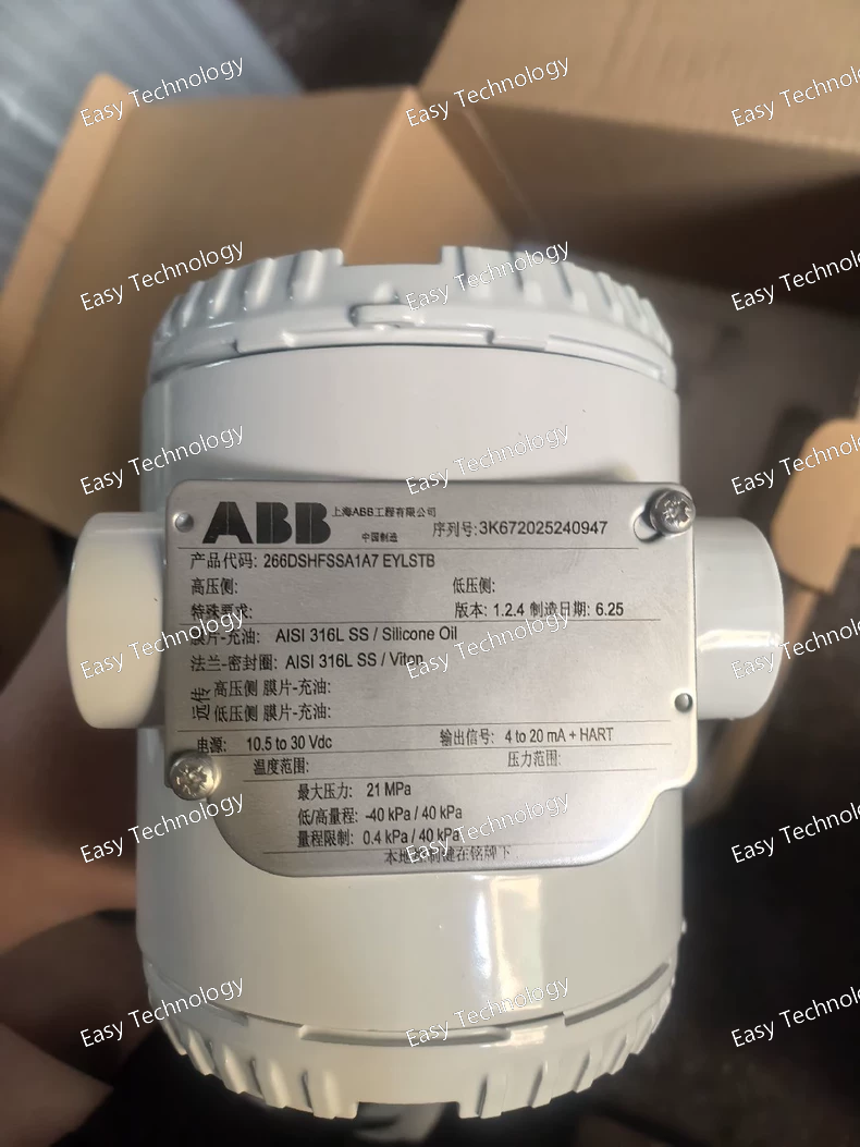
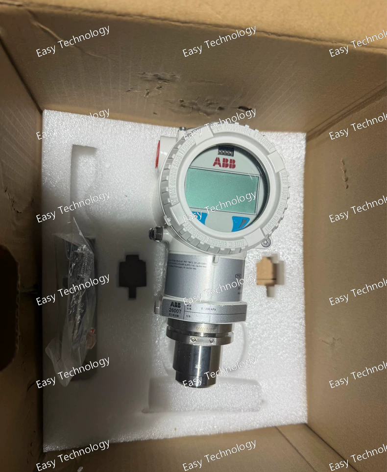
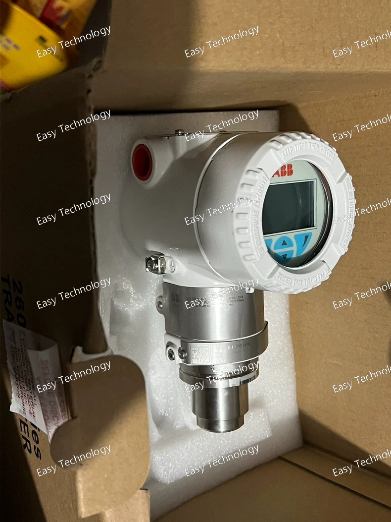
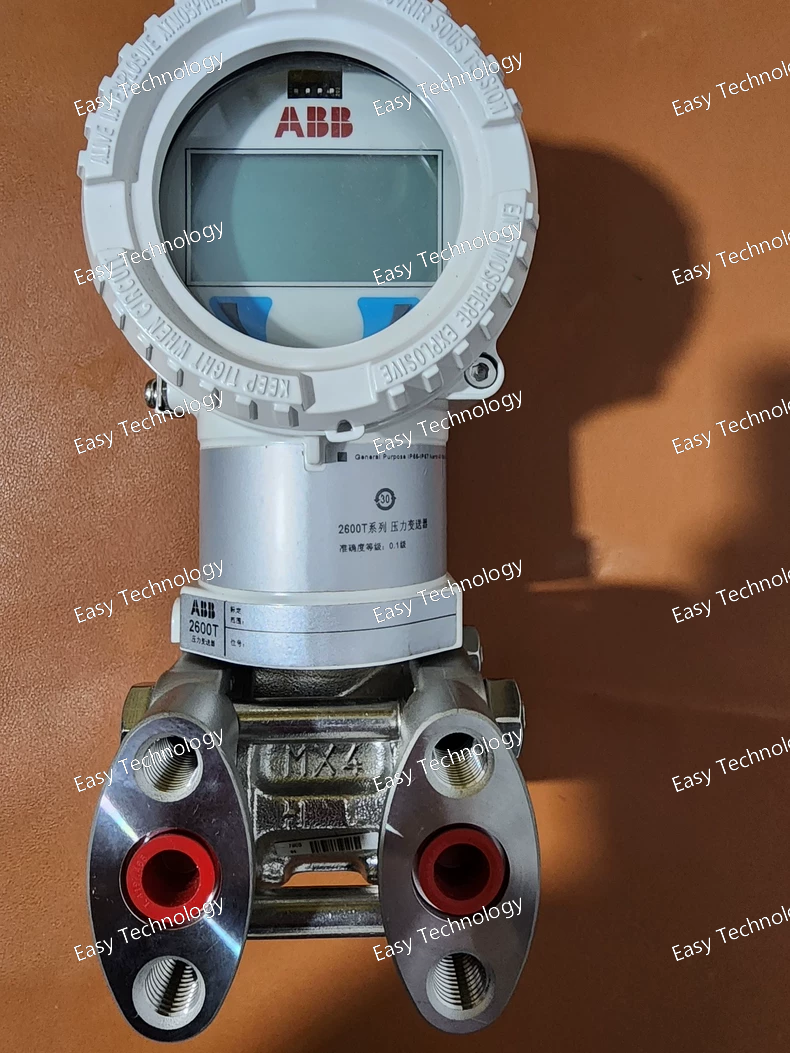
Parameters Category Parameter Specification / Interpretation for 266DSH FSSAIA7/EY/LS/TB General Model Series 2600T Series (DST - Differential Pressure Smart Transmitter) Type Smart dP Transmitter with Remote Diaphragm Seals & Local Interface Output 4-20 mA DC, Two-wire, HART 7 Digital. Measurement Performance Measured Variable Differential Pressure (dP) Calibrated Span (FSSAIA7) Defined by core code. Example: 0 to 40 kPa (0.4 bar). Must be verified from datasheet. Reference Accuracy ±0.055% to ±0.075% of calibrated span (Typical for this grade). Long-Term Stability ±0.1% of URL per year. Options & Features Remote Diaphragm Seals (/EY) Material: 316L SST, Hastelloy, Tantalum, etc. (Specified separately). Capillary Length: Custom (e.g., 1m, 3m, 5m). Fill Fluid: Silicone oil, Inert fluid (matched to process temp.). Local Operator Interface (/LS) Graphical LCD Display. Infrared Push Buttons for Ex ia certified local operation. Certification Package (/TB) ATEX / IECEx: Ex d IIC T6 Gb (Flameproof) & Ex ia IIC T6 Ga (Intrinsic Safety) certificates. May include SIL documentation. Electrical Supply Voltage 10.5 to 45 V DC (Two-wire). Communication HART 7 Protocol. Process Connection (via Seals) Seal Process Connection Flanged (e.g., DIN, ANSI, JIS) or Threaded (e.g., 1/2" NPT). Defined with /EY order. Transmitter Pressure Ports For capillary connection (e.g., 1/4" NPT). Mechanical & Environmental Transmitter Housing Stainless Steel, Flameproof (Ex d) enclosure. Protection Degree IP66 / IP67 / NEMA 4X. Ambient Temperature (Tx) -40°C to +85°C. Process Temperature (Seals) Depends on seal fill fluid. Can exceed +400°C with appropriate seals/fluid.

Parameters Category Parameter Specification / Interpretation for 266DSHFSHB1A7TB General Model Series 2600T Series (DST - Differential Pressure Smart Transmitter) Type Smart dP Transmitter with Local Operator Interface (LOI) Output 4-20 mA DC, Two-wire, HART 7 Digital. Measurement Performance Measured Variable Differential Pressure (dP) Calibrated Span (FSHB1) Defined by suffix "FSHB1". This indicates a specific sensor range. Example: 0 to 400 kPa (4 bar) or 0 to 1 MPa (10 bar). Must be verified from datasheet. Reference Accuracy ±0.055% to ±0.075% of calibrated span (Typical for this performance grade). Long-Term Stability ±0.1% of URL per year. Turndown Ratio Up to 100:1 (Software configurable). User Interface Display Backlit LCD (Local readout of pressure, current, percentage, etc.). Local Controls Push Buttons (for local configuration and navigation). Electrical Supply Voltage 10.5 to 45 V DC (Two-wire). Load Limit R_L ≤ (Vs - 10.5V) / 0.022 A (Ω). Communication HART 7 Protocol. Process Connections & Materials Wetted Parts (HB) Isolating Diaphragms: Hastelloy C-276 (High corrosion resistance). Process Flanges: 316L SST. Fill Fluid Silicone Oil (Standard) or Inert Fluorocarbon (for O2/aggressive service). Pressure Ports 1/4" NPT or G1/2" female. Static Pressure Rating Up to 16 MPa (2320 psi). Mechanical & Environmental Housing Stainless Steel. Protection Degree IP66 / IP67 / NEMA 4X. Process Temperature -40°C to +120°C. Ambient Temperature -40°C to +85°C. Certifications & Safety Explosion Protection (TB) ATEX / IECEx: Ex d IIC T4/T6 Gb (Flameproof) & Ex ia IIC T4/T6 Ga (Intrinsic Safety) options. The "TB" package defines the specific certificates included. Functional Safety SIL 2/3 capable.
Parameters Category Parameter Specification / Interpretation for 266HSHPSBA1 General Model Series 2600T Series (FMT - Flow Multivariable Transmitter) Type Smart Multi-Variable Flow Transmitter (4-20mA HART) Measured Variables Differential Pressure (ΔP), Static Pressure (Ps), Temperature (T). Measurement Performance ΔP Span Range Defined by suffix "PSBA1". This indicates a specific calibrated span. Example: 0 to 250 kPa (2.5 bar). (Must verify from datasheet). Static Pressure (Ps) Range High Range, e.g., 0 to 16 MPa (2320 psi). Temperature (T) Range Integrated RTD: -40°C to +125°C. Reference Accuracy (Flow) ±0.15% of reading (typical for density-compensated flow). Long-Term Stability ±0.1% of Upper Range Limit (URL) per year. Computation & Output Calculated Variable Mass Flow or Volumetric Flow (density-compensated). Fluid Database Pre-loaded with common gas & steam properties; supports user-defined fluids. Primary Element Support Orifice, Venturi, Nozzle, Wedge, Pitot Tube (configurable per ISO/AGA standards). Analog Output 4-20 mA, two-wire. Primary Variable = Flow. Digital Output HART 5/6/7 Protocol. Access to all variables (PV, SV, TV) & diagnostics. Electrical Supply Voltage 10.5 to 42 V DC (Two-wire loop powered). Communication HART (Bell 202 FSK). Process Connections & Materials ΔP Ports 1/4" NPT or G1/2" female. Ps & T Port Integrated, with 1/2" NPT process connection. Wetted Parts Suffix "PSB" indicates materials: Likely standard 316L SST isolating diaphragms and process connections. Mechanical & Environmental Housing Stainless Steel. Protection Degree IP66 / IP67 / NEMA 4X. Process Temperature -40°C to +120°C (wetted parts). Ambient Temperature -40°C to +85°C. Certifications Explosion Protection ATEX / IECEx: Ex ia IIC T4/T6 Ga & Ex d IIC T4/T6 Gb options. Safety Integrity SIL 2/3 capable.
Parameters Category Parameter Specification / Interpretation for 266DSHBSHA1B7LSB1TB General Model Series 2600T Series (DST - Differential Pressure Smart Transmitter) Type Smart dP Transmitter with Local Operator Interface (LOI) Output 4-20 mA DC, Two-wire, HART 7 Digital. Measurement Performance Measured Variable Differential Pressure (dP) Calibrated Span (A1) Defined by suffix "A1". Example: 0 to 100 kPa (1 bar). (Exact value from datasheet). Reference Accuracy ±0.055% to ±0.075% of calibrated span (Typical for this grade). Long-Term Stability ±0.1% of URL per year. Turndown Ratio Up to 100:1. User Interface Display Large, backlit Graphical LCD. Local Controls Infrared Push Buttons (for hazardous area compliance). Functions via Buttons Zero adjustment, range setting (with password), display configuration, diagnostics view. Electrical Supply Voltage 10.5 to 45 V DC (Two-wire). Load Limit R_L ≤ (Vs - 10.5V) / 0.022 A (Ω). Communication HART 7 Protocol. Process Connections & Materials Wetted Parts (BSH) Isolating Diaphragms: Hastelloy C-276 or equivalent. Process Flanges: 316L SST. Fill Fluid Silicone Oil or Inert Fluorocarbon (specify for O2/aggressive service). Pressure Ports 1/4" NPT or G1/2" female. Static Pressure Rating Up to 16 MPa (2320 psi). Mechanical & Environmental Housing Stainless Steel. Protection Degree IP66 / IP67 / NEMA 4X. Process Temperature -40°C to +120°C. Ambient Temperature -40°C to +85°C. Certifications & Safety Explosion Protection (TB) ATEX / IECEx: Ex d IIC T4/T6 Gb (Flameproof) & Ex ia IIC T4/T6 Ga (Intrinsic Safety) - Dual Certification. Local Safety (LSB1) Infrared push buttons certified for Ex ia intrinsic safety, allowing safe operation in Zone 0/1. Functional Safety SIL 2/3 capable.
Parameters Category Parameter Specification / Interpretation for 266HSHQKBB1 General Model Series 2600T Series (FMT - Flow Multivariable Transmitter) Type Smart Multi-Variable Flow Transmitter (4-20mA HART) Measured Variables Differential Pressure (ΔP), Static Pressure (Ps), Temperature (T). Measurement Performance ΔP Span Range Wide range, model-specific. The suffix QKBB1 defines a specific range. Example: 0 to 100 kPa (1 bar). Static Pressure (Ps) Range High Range, e.g., 0 to 16 MPa (2320 psi). Temperature (T) Range Integrated RTD: -40°C to +125°C. Reference Accuracy (Flow) ±0.15% of reading (typical for compensated flow). Long-Term Stability ±0.1% of URL per year. Computation & Output Calculated Variable Mass Flow or Volumetric Flow (density-compensated). Fluid Database Pre-loaded with common gas & steam properties; user-definable. Primary Element Support Orifice, Venturi, Nozzle, Wedge, Pitot Tube (per ISO/AGA). Analog Output 4-20 mA, two-wire. Primary Variable = Flow. Digital Output HART 5/6/7 Protocol. Access to PV, SV (Ps), TV (T). Electrical Supply Voltage 10.5 to 42 V DC (Two-wire loop powered). Communication HART (Bell 202 FSK). Process Connections & Materials ΔP Ports 1/4" NPT or G1/2" female. Ps & T Port Integrated, with 1/2" NPT process connection. Wetted Parts Suffix HQK indicates materials: Likely Hastelloy C-276 isolating diaphragms for superior corrosion resistance. BB1 indicates flange/connection type. Mechanical & Environmental Housing Stainless Steel. Protection Degree IP66 / IP67 / NEMA 4X. Process Temperature -40°C to +120°C (wetted parts). Ambient Temperature -40°C to +85°C. Certifications Explosion Protection ATEX / IECEx: Ex ia IIC T4/T6 Ga & Ex d IIC T4/T6 Gb options. Safety Integrity SIL 2/3 capable.
Parameters Category Parameter Specification / Interpretation for 266DSHESSA1B1 General Model Series 2600T Series (DST - Differential Pressure Transmitter) Type Smart 4-20 mA/HART Differential Pressure Transmitter Output Signal 4-20 mA DC, two-wire, with HART digital overlay. Measurement Performance Measured Variable Differential Pressure (dP) Span Limits Specific range defined by suffix. Common spans from 0.1 kPa (1 mbar) to several MPa. "ESA1" likely indicates a specific calibrated span (e.g., 0-40 kPa). Reference Accuracy ±0.065% of calibrated span (Typical for high-end 2600T). Long-Term Stability ±0.1% of URL per year (Typical). Turndown Ratio Up to 100:1 (Software configurable). Electrical Supply Voltage 10.5 to 45 V DC (Standard for two-wire loop). Load Limit R_L ≤ (Vs - 10.5V) / 0.022 A Communication HART Protocol (Bell 202 FSK). Process Connections & Materials Wetted Parts Isolating Diaphragms: 316L SST Process Flanges/Fittings: 316 SST Fill Fluid Silicone oil (standard) or Inert Fluorocarbon (for aggressive media/O2 service). Pressure Ports 1/4" NPT female or G1/2" (Common). Static Pressure Limit Up to 16 MPa (2320 psi) (Flange dependent). Overpressure Limit Up to full static pressure rating without damage. Mechanical & Environmental Housing Material Stainless Steel or Epoxy-coated Aluminum. Protection Degree IP66 / IP67 / NEMA 4X Display (Option) Local LCD indicator (Optional, not all "B1" have it). Process Temperature Limits -40°C to +120°C (Standard fill fluid). Ambient Temperature Limits -40°C to +85°C Certifications Explosion Protection ATEX / IECEx: Ex ia IIC T4/T6 Ga (Intrinsic Safety) & Ex d IIC T4/T6 Gb (Flameproof) options. Other CE, SIL 2/3 capable.
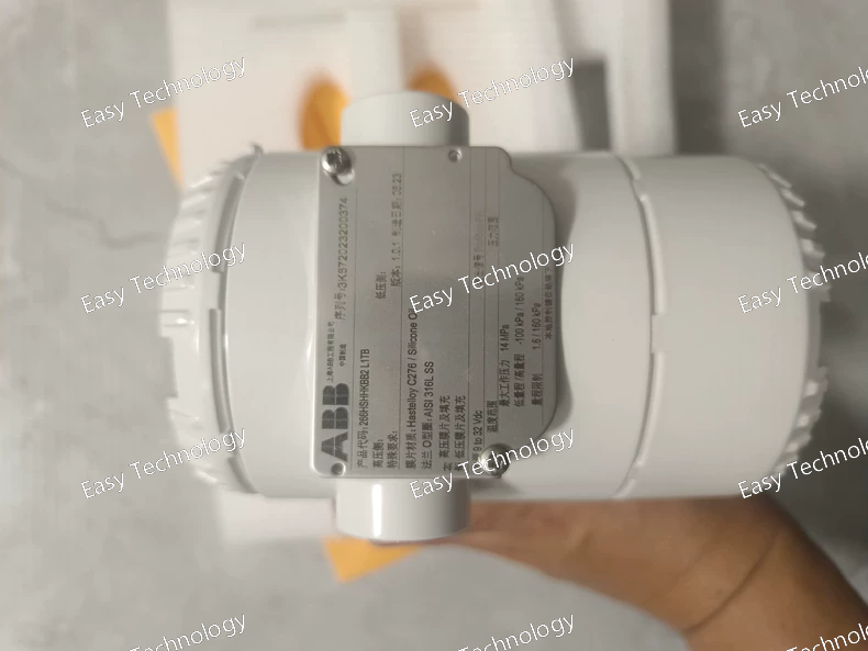
Parameters Category Parameter Specification / Interpretation for 266HSHHKBB2L1TB General Model Series 2600T Series (FMT - Flow Multivariable Transmitter) Type Smart Multi-Variable Flow Transmitter (4-20mA HART) Measured Variables ΔP (Differential Pressure), Ps (Static Pressure), T (Temperature). Measurement Performance ΔP Span Range Wide range, typically from 0.1 kPa to 3 MPa (exact min/max defined by suffix). Static Pressure (Ps) Range High Range, e.g., 0 to 16 MPa (2320 psi). Temperature (T) Range Integrated RTD, e.g., -40°C to +125°C. Reference Accuracy (Flow) ±0.15% of rate (typical for compensated flow). Long-Term Stability ±0.1% of URL per year. Computation & Output Calculated Variable Mass Flow or Volumetric Flow (compensated). Fluid Properties Pre-loaded database + user-defined. Primary Element Support Orifice, Venturi, Nozzle, Wedge, Pitot Tube (ISO/AGA). Analog Output 4-20 mA, two-wire. Primary Variable = Flow. Digital Output HART 5/6/7. Access to all variables (PV, SV, TV) & diagnostics. Electrical Supply Voltage 10.5 to 42 V DC (two-wire loop). Communication Protocol HART (Bell 202 FSK). Process Connections & Materials ΔP Ports 1/4" NPT or G1/2" female (High & Low side). Ps & T Port Integrated, with 1/2" NPT process connection. Wetted Parts (Suffix Defined) HHK: Likely indicates Hastelloy C-276 diaphragms/seals for high corrosion resistance. BB2: Likely defines flange type/rating. Mechanical & Environmental Housing Compact design, Stainless Steel or Aluminum. Protection Degree IP66 / IP67 / NEMA 4X Process Temperature -40°C to +120°C (for wetted parts). Ambient Temperature -40°C to +85°C Certifications Explosion Protection ATEX / IECEx: Ex ia IIC T4/T6 Ga (Intrinsic Safety) & Ex d IIC T4/T6 Gb (Flameproof) options. Safety Integrity SIL 2/3 capable.
 TEL: Grace +86 13600179521
  Mail: info@hongkongeasy.com jilineasyyi@outlook.com
 Q Q:615739355
 ADDRESS:Unit 12, 20th Floor, Good View Commercial Centre, 2-16 Garden Street, Mong Kok, Hong Kong
 whats app


