
Industrial Controller
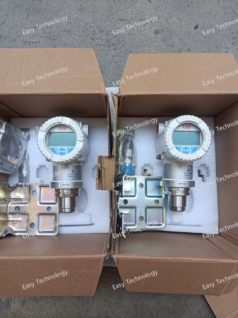
All product are in stock,guaranteed delivery within 3-7 days.


PRODUCT
PICTURE
BRAND
DESCRIBE
STOCK
DOWNLOAD
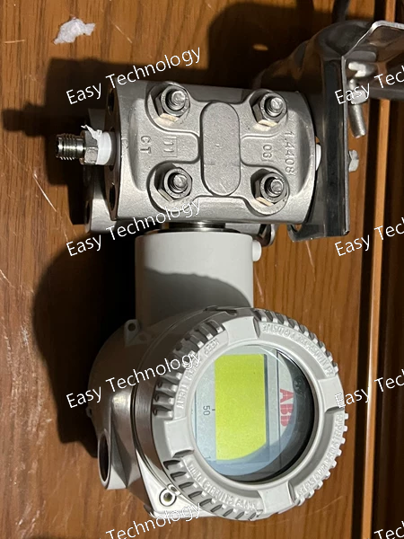
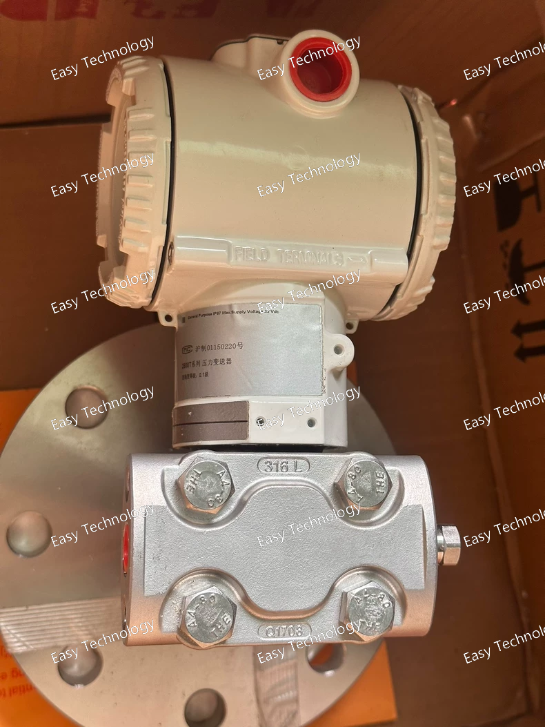
Specifications General Type: Differential Pressure Transmitter Series: ABB 266 HSH (High Static Pressure) Output: 4–20 mA, two-wire with HART protocol Sensor Type: Digital capacitive sensor with temperature compensation Measurement Performance Reference Accuracy: ±0.04% of span (depending on range) Repeatability: ±0.02% of span Turn-Down Ratio: Up to 100:1 Response Time: <100 ms (depending on damping) Long-Term Stability: ±0.1% URL over 10 years Pressure Ratings Differential Pressure Range: According to PSBB7 sensor module selection Static Pressure Limit: Up to 105 MPa (1050 bar) Proof Pressure: 1.5 × static rating Overpressure Protection: Integrated mechanical system Materials & Construction Wetted Materials: Stainless steel, Hastelloy, or optional alloys per PSBB7 code Fill Fluid: Silicone oil or inert fluid Housing: Aluminum or stainless steel (as defined by L9TB) Process Connections: High-pressure flanges or threaded adapters Electrical & Communication Power Supply: 10.5–45 VDC Signal: 4–20 mA + HART digital Load Resistance (HART): ≤600 Ω Local Configuration: Push-button or optional LCD interface Environmental Conditions Electronics Operating Temperature: –40 to +85 °C Process Temperature: Dependent on sensor and fill fluid Humidity: 0–100% RH, non-condensing Ingress Protection: IP67 / IP68 (depending on housing selection) Vibration Resistance: Up to 10 g, 10–2000 Hz Certifications / Standards Explosion Protection: Ex ia / Ex d / Ex nA options depending on code Compliance: ATEX, IECEx, PED, CE EMC & Surge Protection: Industrial-grade standards
Specifications General Type: Differential Pressure Transmitter Series: ABB 266 ASTC Output: 4–20 mA, two-wire with HART protocol Technology: Digital capacitive sensor with temperature compensation Measurement Performance Reference Accuracy: ±0.04% of span (depending on calibration) Repeatability: ±0.02% of span Turn-Down Ratio: Up to 100:1 Response Time: Typically <100 ms Long-Term Stability: ±0.1% of span over 10 years Pressure Ratings Differential Pressure Range: Configurable according to selected sensor range Static Pressure Limit: As defined by KBNB1 sensor module Overpressure Protection: Integrated mechanical system Mechanical / Materials Wetted Parts: Stainless steel (per KBNB1 selection) Fill Fluid: Silicone or inert oil (depending on configuration) Housing: Aluminum or stainless steel (per EYL1 selection) Process Connections: Standard 266 manifold or threaded connections Electrical Power Supply: 10.5–45 VDC Load Resistance: Up to 600 Ω (HART) Signal: 4–20 mA with HART digital output Local Configuration: Push-button interface if equipped Environmental Conditions Electronics Temperature Range: –40 to +85 °C Process Temperature: According to fill fluid and sensor selection Humidity: 0–100% RH (non-condensing) Ingress Protection: IP66 / IP67 depending on housing and entry options Vibration Resistance: Up to 10 g, 10–2000 Hz Certifications Explosion Protection: Ex ia / Ex d / Ex nA options depending on code Compliance: ATEX, IECEx, PED, CE Surge / EMC Protection: Per industrial standards
Specifications General Type: Differential Pressure Transmitter Series: ABB 266 DSH (High Static Pressure Differential Model) Output: 4–20 mA with HART communication Sensor Type: Digital capacitive differential sensor Configuration Code: HSSA2B7LSTB Measurement Performance Reference Accuracy: Up to ±0.04% of span (depending on calibration) Long-Term Stability: ±0.1% of URL for up to 10 years Turn-Down Ratio: Up to 100:1 (application dependent) Response Time: Fast dynamic response suitable for flow monitoring Pressure Ratings Differential Pressure Range: As per DSH high-static sensor selection Static Pressure Limit: Up to 41 MPa / 6000 psi (DSH high-static variant) Overpressure Protection: Integrated mechanical overpressure system Materials Wetted Parts: Stainless steel (per “HSSA…” code) Fill Fluid: Silicone oil Sensor Body: High-strength stainless steel Housing: Aluminum housing with protective coating Process & Mechanical Process Connections: Standard 266 DP/DS manifold-style connections Mounting: Compatible with ABB 266 bracket and manifold systems Environmental Protection: IP66 / IP67 depending on electrical entry Electrical & Communication Communication Protocol: HART 7 Power Supply: 10.5–45 VDC depending on loop load Electrical Entry: As defined by “B7LSTB” configuration Zero/Span Adjustment: Via HART or local interface (if equipped) Environmental Conditions Ambient Temperature: –40 °C to +85 °C (electronics) Process Temperature: According to fill-fluid limitations EMI / RFI Immunity: Industrial-grade protection Certifications / Options Surge protection Harsh-environment enclosure options Industry-standard approvals depending on configuration
Specifications General Type: Differential Pressure Transmitter Series: ABB 266 HSH (High Static Pressure Version) Output Signal: 4–20 mA with HART communication Technology: Digital capacitive sensor with advanced temperature compensation Measurement Performance Accuracy: Up to ±0.04% of calibrated span (depending on range) Long-Term Stability: Typically ±0.1% of URL for 10 years Response Time: Fast dynamic response suitable for flow applications Pressure Ratings Differential Pressure Range: According to HSH high static-pressure sensor limits Static Pressure Rating: Up to 41 MPa / 6000 psi (HSH high-static variant) Overpressure Protection: Integrated mechanical overpressure system Materials & Construction Wetted Materials: Stainless steel (per code “ESB…”) Fill Fluid: Silicone oil Housing: Aluminum housing with coating Process Connection: Standard 266 manifold-compatible connections Electrical & Communication Protocol: HART 7 Power Supply: 10.5–45 VDC (depending on load) Electrical Entry: As defined in “B6T…” portion of model code Certifications / Options Surge and transient protection Industrial environmental protection rating Mounting accessories per “L1B6TB” configuration Environmental Operating Temperature: –40 °C to +85 °C (electronics) Process Temperature: According to fill fluid limits Ingress Protection: IP66 / IP67 (depending on housing/entry selection)
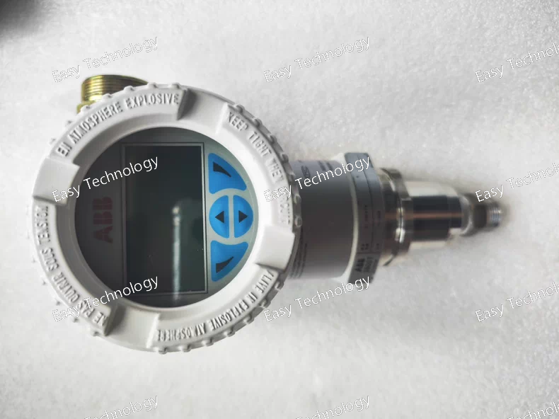
Specifications General Type: Differential Pressure Transmitter Series: ABB 266 Series Model: 266HSH – High Static Pressure DP Transmitter Output: 4–20 mA, two-wire with HART communication Measurement Performance Measured variable: Differential pressure (DP) Upper Range Limit (URL): Up to 10 MPa (depending on sensor range) Turn-down ratio: Up to 100:1 Reference accuracy: ±0.04% URL Repeatability: ±0.02% URL Long-term stability: ±0.1% URL over 10 years Response time: < 100 ms Adjustable damping: 0 to several seconds Pressure Ratings Static pressure rating: Up to 105 MPa (1050 bar) Proof pressure: 1.5 × static rating Overpressure protection: Integrated mechanical overload system Environmental Conditions Electronics operating temperature: –40 to +85 °C Process temperature: Depends on diaphragm and fill fluid selection Humidity: 0–100% RH (non-condensing) Vibration resistance: Up to 10 g, 10–2000 Hz Protection rating: IP67 / IP68 (depending on housing option) Electrical Characteristics Power supply: 10.5–45 VDC Signal: 4–20 mA + HART digital Load (HART): Up to 600 Ω Reverse polarity protection: Built-in EMC compliance: Meets IEC/EN industrial EMC standards Mechanical / Materials Wetted materials: Stainless steel, Hastelloy, or special alloys (per ESBA7 code) Process connections: High-pressure DP flanges or threaded adapters Fill fluid: Silicone oil or inert fluid (based on configuration) Housing: Aluminum or stainless steel (per LSTB selection) Mounting: Direct mount or mounting bracket options Display & Local Interface Local display: Optional LCD with bar-graph indication Local configuration: Two push-button setup Remote configuration: Via HART communicator, DTM, or EDD tools Certifications Explosion protection: Ex ia / Ex d / Ex nA (depending on selected code) Compliance: ATEX, IECEx, PED, CE Ingress protection: IP67 / IP68
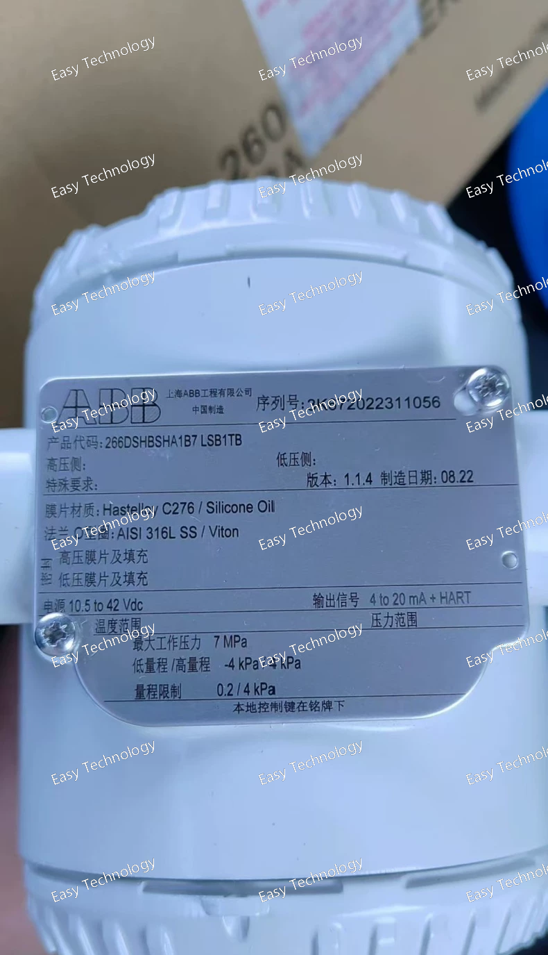
Specifications General Type: Differential Pressure Transmitter Series: ABB 266 Series Model: 266DSH – High Static Pressure DP Transmitter Output signal: 4–20 mA, two-wire with HART protocol Measurement Performance Measured variable: Differential pressure (DP) Upper Range Limit (URL): Up to 10 MPa (depending on selected sensor code) Turn-down capability: Up to 100:1 Reference accuracy: ±0.04% of URL Repeatability: ±0.02% of URL Long-term stability: ±0.1% URL over 10 years Damping: Adjustable (0 to several seconds) Response time: < 100 ms (depending on configuration) Pressure Limits Static pressure rating: Up to 41 MPa (410 bar) Proof pressure: 1.5 × static pressure rating Overpressure protection: Integrated mechanical overload system Environmental Conditions Electronics operating temperature: –40 to +85 °C Process temperature: Depends on diaphragm material and fill fluid Humidity: 0–100% RH, non-condensing Ingress protection: IP67 or IP68 (depending on housing option) Vibration resistance: Up to 10 g, 10–2000 Hz Electrical Characteristics Power supply: 10.5–45 VDC Load (HART): Max. 600 Ω Signal: 4–20 mA + HART digital Polarity protection: Built-in EMC compliance: Conforms to IEC/EN industrial EMC standards Mechanical / Materials Wetted materials: Stainless steel, Hastelloy, or optional alloys (based on BHA1B7 selection) Process connections: DP flanges or threaded high-pressure adapters Fill fluid: Silicone oil or inert fluid (per code BHA1B7) Housing: Aluminum or stainless steel (as specified in LSB1TB) Mounting: Direct mount or bracket installations Display & Local Interface Local display: Optional LCD with bar-graph and alphanumeric readout Local configuration: Two push-button interface Remote configuration: Via HART communicator or DTM/EDD tools Certifications Explosion protection: Options include Ex ia, Ex d, Ex nA (depending on device code) Compliance: ATEX, IECEx, PED, CE Ingress protection: IP67 / IP68 depending on terminal and housing type
Specifications General Type: Differential Pressure Transmitter Series: ABB 266 Series Model: 266DSH – High Static Pressure DP Transmitter Output: 4–20 mA, two-wire with HART protocol Measurement Performance Measured variable: Differential pressure (DP) Upper Range Limit (URL): Up to 10 MPa (depending on selected sensor range) Turn-down ratio: Up to 100:1 Reference accuracy: ±0.04% URL Repeatability: ±0.02% URL Stability: ±0.1% URL over 10 years Damping: Adjustable from 0 to several seconds Response time: < 100 ms (depending on configuration) Pressure Limits Static pressure rating: Up to 41 MPa (410 bar) Proof pressure: 1.5 × static rating Overpressure protection: Integrated mechanical overload system Minimum DP detectability: Based on selected range code Environmental Conditions Electronics operating temperature: –40 to +85 °C Process temperature: According to diaphragm material and fill fluid Ambient humidity: 0–100% RH (non-condensing) Vibration resistance: 10 g, 10–2000 Hz Protection rating: IP67 or IP68 (depending on housing selection) Electrical Characteristics Power supply: 10.5–45 VDC Signal: 4–20 mA + HART Load: Up to 600 Ω for HART Polarity protection: Built-in EMC compliance: Meets IEC/EN industrial EMC standards Mechanical / Materials Wetted materials: Stainless steel / Hastelloy / optional exotic alloys Process connections: Differential pressure flanges or threaded adapters Fill fluid: Silicone oil or inert fill (per ESSB1B1 code) Housing: Aluminum or stainless steel (per model code) Mounting: Direct or bracket-based installation Display & Interface Local display: Optional LCD (V1E and L1 options in code) Local configuration: Two push-button keypad Remote configuration: HART communicator or DTM/EDD software Certifications Explosion protection: Ex ia / Ex d / Ex nA (depending on configuration) Safety standards: ATEX, IECEx, PED, CE Ingress protection: IP67 / IP68 (depending on selected housing and terminals)
Specifications General Type: Differential Pressure Transmitter Series: ABB 266 Model: 266HSH (High Static Pressure Version) Output: 4–20 mA, two-wire with HART communication Measurement Performance Measured variable: Differential pressure (DP) URL (Upper Range Limit): Up to 0.62 MPa to 10 MPa depending on sensor range (HSH high-pressure module) Turn-down ratio: Up to 100:1 Reference accuracy: ±0.04% of URL Repeatability: ±0.02% URL Long-term stability: ±0.1% URL over 10 years Response time: ≤ 100 ms (configurable damping available) Pressure Limits Static pressure rating: Up to 105 MPa (1050 bar) Overpressure protection: Integrated mechanical overload system Proof pressure: 1.5 × static pressure rating Environmental Conditions Operating temperature (electronics): –40 to +85 °C Ambient humidity: 0–100% RH, non-condensing Process temperature: According to diaphragm material and fill fluid Ingress protection: IP67 or IP68 (depending on housing configuration) Vibration resistance: 10–2000 Hz, 10 g Electrical Power supply: 10.5 to 45 VDC (depending on load) Load (HART): ≤ 600 Ω Output signal: 4–20 mA + HART (linear or square-root mode) EMC compliance: Meets IEC/EN industrial EMC standards Mechanical / Materials Wetted parts: Stainless steel / Hastelloy / optional exotic materials (depending on FSBA2 selection) Process connections: Standard DP flange or threaded high-pressure connections Housing material: Aluminum or stainless steel (L1B6TB configuration defines final selection) Fill fluid: Silicone or inert oil (depending on code) Display & Local Interface Local display: Optional LCD with bar-graph and alphanumeric indication Local configuration: Two front keys for zero/span and parameter setup Remote configuration: Via HART communicator or PC-based DTM/EDD tools Certifications Explosion protection options: Ex ia, Ex d, Ex nA (depending on selected code) Safety approvals: PED, ATEX, IECEx, CE Ingress protection: IP67 / IP68 depending on housing
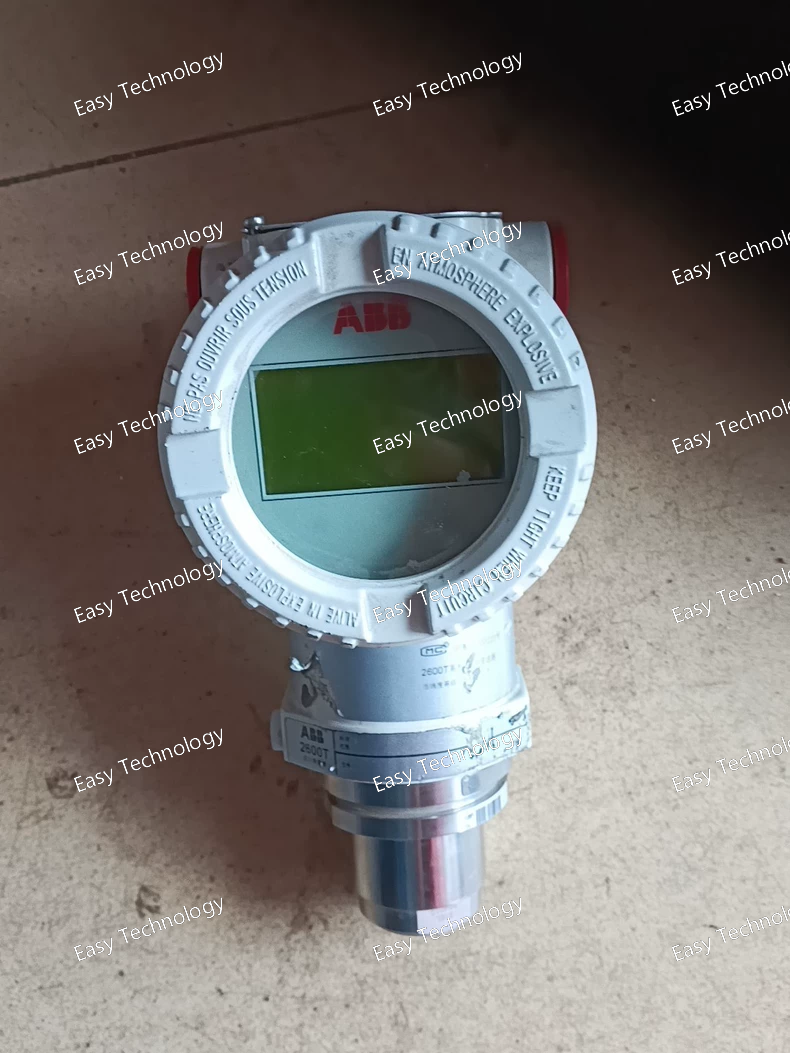
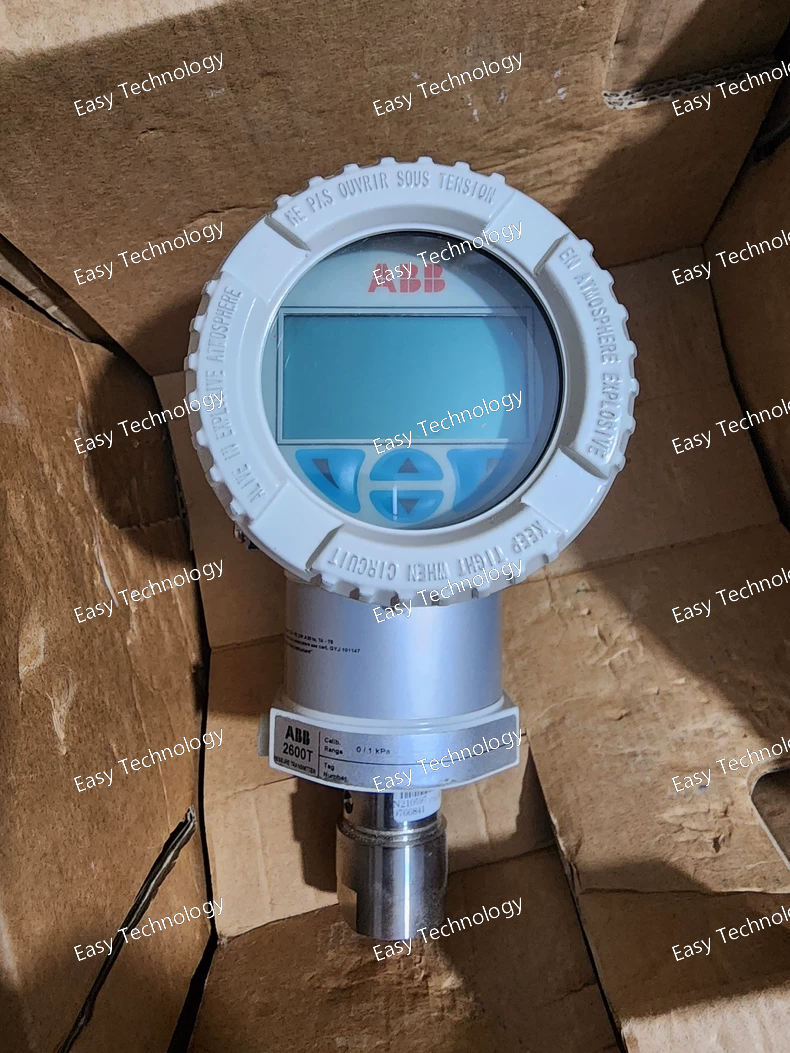
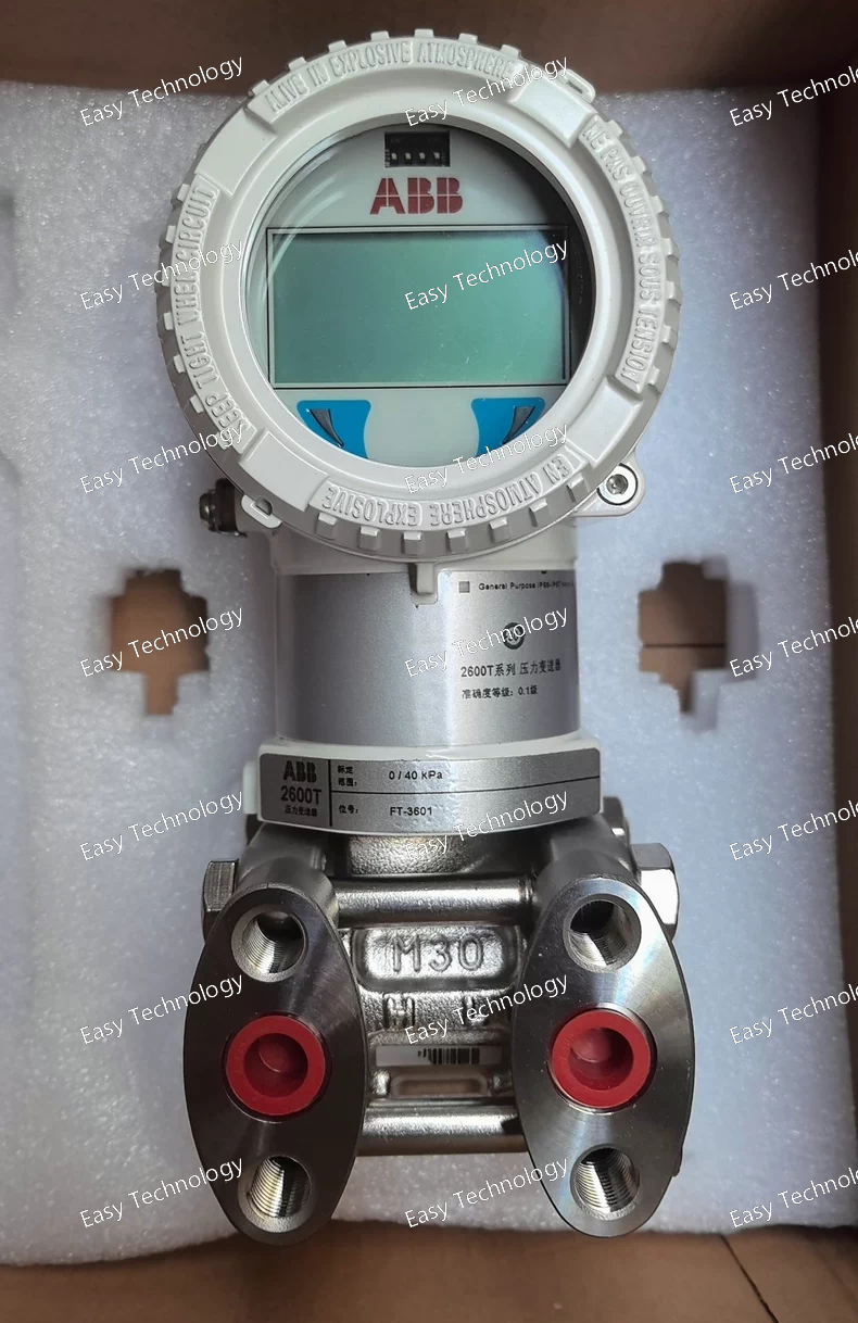
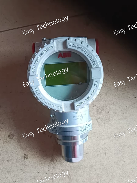
Specifications Type: Differential Pressure Transmitter Series: ABB 2600T Model: 265DS (AMKA6B1 configuration) Measurement Performance Measured variable: Differential pressure (DP) Span range: 0.05 kPa to 10,000 kPa (depending on selected sensor range) Turn-down ratio: Up to 100:1 Reference accuracy: ±0.04% of upper range limit (URL) Stability: ±0.1% URL over 10 years Long-term drift: Extremely low due to digital sensing architecture Output / Communication Output signal: 4–20 mA, two-wire Communication protocol: HART (depending on AMKA6B1 selection) Update rate: 32 ms typical Damping: Adjustable Pressure Limits Static pressure rating: Up to 41 MPa (varies per sensor module selection) Overpressure protection: Integral overload design; 1.5 × static pressure test Environmental Conditions Operating temperature: –40 to +85 °C (electronics) Process temperature: Based on wetted materials and fill fluid Humidity: 0–100% RH, non-condensing Ingress protection: IP67 or IP68 (depending on housing option) Electrical Power supply: 10.5 to 45 VDC (depending on load) Power consumption: ≤ 22 mA EMC compliance: Meets international EMC and low-voltage directives Mechanical / Materials Wetted materials: Stainless steel / Hastelloy / Tantalum (as specified in code AMKA6B1) Process connections: Standard DP flange connections or threaded adapters Fill fluid: Silicone oil or inert fluid depending on configuration Housing material: Aluminum or stainless steel housing (per model code) Display / Local Interface Local display: Optional LCD with bar-graph and alphanumeric indication Local configuration: Two push-button keypad Remote configuration: Via HART communicator or PC-based DTM software Certifications Explosion protection (options): Ex ia, Ex d, Ex nA (depending on code) Safety compliance: PED, ATEX, IECEx, CE, and other industrial standards
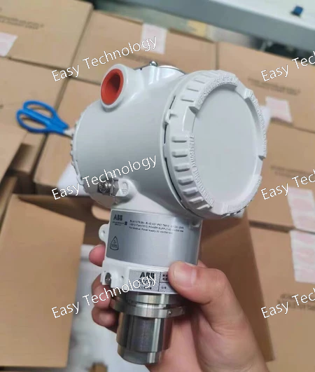
Technical Parameters Parameter Specification Measured Variable Gauge Pressure Range / Span High-range pressure (specific span depends on HSBA1 sensor) Reference Accuracy ±0.06% of span (typical) Turn-down Ratio Up to 100:1 Static Pressure Rating Up to 420 bar (depends on sensor and housing) Overload Capability Full static pressure without damage Output Signal 4–20 mA analog + HART communication Power Supply 10.5–45 VDC Wetted Parts Material Stainless Steel Housing / Enclosure Robust industrial housing (HS series) Local Display Optional (depending on configuration) Electrical Connection Terminal block or conduit entry (model dependent) Environmental Rating IP66/67 depending on installation Process Temperature –40 to +120 °C (depending on fill fluid and configuration) Ambient Temperature –40 to +85 °C Certifications HART-compatible, suitable for industrial environments
Technical Parameters Parameter Specification Measured Variable Gauge Pressure Range / Span High range (depending on MSBA8 sensor option) Reference Accuracy ±0.06% of span (typical) Turn-down Ratio Up to 100:1 Static Pressure Rating Up to 420 bar (depends on sensor and housing) Overload Capability Full static pressure without damage Output Signal 4–20 mA analog + HART communication Power Supply 10.5–45 VDC Wetted Parts Material Stainless Steel (MS) Housing / Enclosure BA8 robust housing for industrial installation Local Display LCD display with Through-The-Glass configuration (EZL1) Electrical Connection Terminal block (TB) Environmental Rating IP66/67 depending on installation Process Temperature –40 to +120 °C (depending on fill fluid and configuration) Ambient Temperature –40 to +85 °C Certifications HART-compatible, suitable for industrial environments
Technical Parameters Parameter Specification Measured Variable Differential Pressure Range / Span High or medium range depending on ESSA1B sensor selection Reference Accuracy ±0.06% of span (typical) Turn-down Ratio Up to 100:1 Static Pressure Rating Up to 420 bar (depends on sensor and housing) Overload Capability Full static pressure without damage Output Signal 4–20 mA analog + HART communication Power Supply 10.5–45 VDC Wetted Parts Material Stainless Steel Housing / Enclosure Standard industrial housing (DDH series) Local Display Optional, depends on configuration Electrical Connection Terminal block or conduit entry (model dependent) Environmental Rating IP66/67 depending on installation Process Temperature –40 to +120 °C (depending on fill fluid and configuration) Ambient Temperature –40 to +85 °C Certifications HART-compatible, suitable for industrial environments
 TEL: Grace +86 13600179521
  Mail: info@hongkongeasy.com jilineasyyi@outlook.com
 Q Q:615739355
 ADDRESS:Unit 12, 20th Floor, Good View Commercial Centre, 2-16 Garden Street, Mong Kok, Hong Kong
 whats app


