
Industrial Controller
All product are in stock,guaranteed delivery within 3-7 days.


PRODUCT
PICTURE
BRAND
DESCRIBE
STOCK
DOWNLOAD
Specifications General Type: Miniature Circuit Breaker (MCB) Series: ABB S200 Poles: Single-pole (1P) Rated Current (In): 10 A Breaking Capacity (Icn): 6 kA at 230/400 V AC Electrical Characteristics Rated Voltage: 230/400 V AC Rated Frequency: 50/60 Hz Tripping Type: B-characteristic (instantaneous trip 3–5 × In) Number of Poles: 1 Residual Current Protection: Not included (standard MCB) Mechanical & Installation Mounting: DIN rail 35 mm Terminal Type: Screw terminals Torque Rating: 2.0–2.5 Nm Dimensions (H × W × D): 80 × 17.5 × 70 mm Weight: Approx. 0.1 kg Performance & Standards Mechanical Endurance: 10,000 operations Electrical Endurance: 4,000 operations Operating Temperature: –25 °C to +40 °C Protection Class: IP20 (installed in enclosure) Standards Compliance: IEC/EN 60898-1, IEC/EN 60947-2 Safety Approvals: CE marked Features Compact and lightweight design for residential and commercial panels High breaking capacity for enhanced safety Thermomagnetic protection for both overload and short-circuit conditions Easy installation with standard DIN rail mounting
Parameters 1. Mechanical & General Specifications Type: Modular 3-Level Combination Terminal Block System: ABB UK 2.6 N Series Number of Levels: 3 Key Features: Disconnect Switch, Test Socket, Built-in Shunt Resistor Connection Technology: Screw Clamp (L) Conductor Entry: Front Entry Housing Material: Polyamide (PA), Grey (typical for 'A' marking series) Mounting: Snap-on mounting for 35mm top-hat DIN rail (EN 60715)
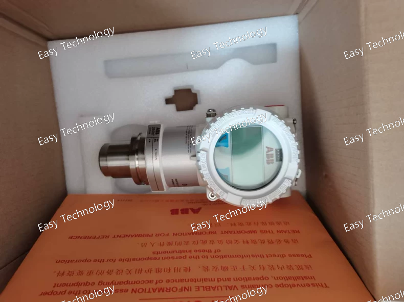
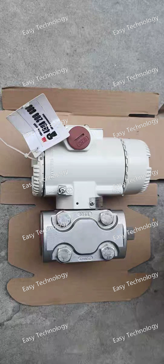
Specifications General Type: Differential Pressure Transmitter Series: ABB 266 HDHH (High Differential / High Static Pressure) Output: 4–20 mA two-wire with HART communication Sensor Technology: Digital capacitive sensor with temperature compensation Measurement Performance Reference Accuracy: ±0.04% of span Repeatability: ±0.02% of span Turn-Down Ratio: Up to 100:1 Response Time: <100 ms Long-Term Stability: ±0.1% of URL over 10 years Pressure Ratings Differential Pressure Range: Configurable per RMB1 sensor selection Static Pressure Rating: High static pressure variant, suitable for up to 105 MPa Proof Pressure: 1.5 × static rating Overpressure Protection: Integrated mechanical system Materials & Construction Wetted Materials: Stainless steel / Hastelloy / optional alloys (per RMB1 selection) Fill Fluid: Silicone or inert fluid Housing: Aluminum or stainless steel (per configuration) Process Connections: High-pressure flanges or threaded adapters Electrical & Communication Power Supply: 10.5–45 VDC Output Signal: 4–20 mA + HART digital Load Resistance (HART): ≤600 Ω Local Configuration: Optional push-button or LCD interface Environmental Conditions Electronics Operating Temperature: –40 to +85 °C Process Temperature: According to sensor and fill fluid Humidity: 0–100% RH, non-condensing Ingress Protection: IP67 / IP68 depending on housing and terminals Vibration Resistance: Up to 10 g, 10–2000 Hz Certifications / Standards Explosion Protection: Ex ia / Ex d / Ex nA (depending on configuration) Compliance: ATEX, IECEx, PED, CE
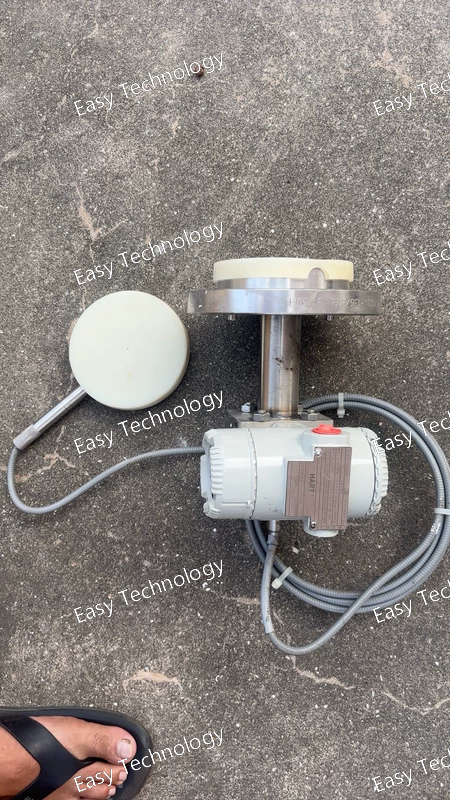
Specifications General Type: Temperature Transmitter Model: TTF300-Y0 Application: Industrial process temperature measurement Mounting: Head-mount or DIN rail (depending on configuration) Input Supported Sensors: RTDs: Pt100, Pt1000 (2-, 3-, or 4-wire) Thermocouples: Types J, K, T, E, N, R, S, B Input Range: –200 to +600 °C (depending on sensor type) Sensor Connection: Screw terminals, standard industrial wiring Output Signal: 4–20 mA two-wire Load Resistance: 0–600 Ω typical Communication: Optional HART (depending on configuration) Accuracy & Performance Accuracy: ±0.1% of span (depending on sensor and range) Response Time: <1 s (depending on sensor) Turn-Down Ratio: Up to 100:1 Long-Term Stability: ±0.1% of span per year Power Supply Voltage: 10–45 VDC two-wire loop powered Current Consumption: <20 mA Environmental Conditions Operating Temperature: –40 to +85 °C Storage Temperature: –40 to +85 °C Humidity: 0–95% RH, non-condensing Ingress Protection: IP65 / IP66 (depending on mounting) Vibration & Shock Resistance: IEC 60068 compliant Materials & Housing Housing Material: Aluminum or plastic (depending on configuration) Process Connection: Standard head-mount thermowell or direct mounting Certifications & Standards Safety & EMC Compliance: CE, IEC/EN 61326
Parameters Code Segment Parameter English Description Explanation 266 Series / Type 3-Level Feed-Through Terminal Block Indicates a modular terminal with three independent connection levels (layers): input, an intermediate potential distribution layer, and output. HSHHS Function / Configuration With Test Sockets and Bridging Points Defines the electrical layout. H = connection point with a test socket/jack. S = connection point for screw-type bridging/jumpering. The sequence H-S-H-H-S describes a complex configuration for potential distribution and measurement, commonly used in Current Transformer (CT) circuits or control circuits requiring isolation and test points. B7 Marking / Color Write-on Marking Strip, Color Code (e.g., Black/Grey) B = equipped with a write-on marking area. 7 = specific color (often black or dark grey) for housing or marker. EZL Connection Technology Spring Clamp Connection (EZ), Side Entry EZ = ABB's "Easy" spring-loaded clamp, tool-operated. L = Lateral (side) cable entry direction. ST Conductor Type For Solid or Stranded Conductors Suitable for both solid core and stranded wires without needing wire-end ferrules (unless specified by local regulations). B Mounting Snap-on Mounting for 35mm Top-Hat DIN Rail Can be snapped directly onto a standard EN 60715 35mm x 7.5mm or 35mm x 15mm DIN rail.
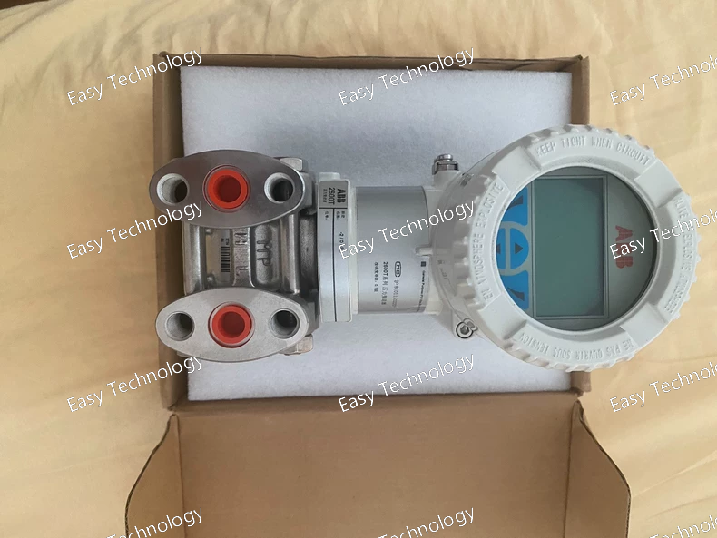
Specifications General Type: Differential Pressure Transmitter Series: ABB 266 DSH (High Static Pressure) Output: 4–20 mA two-wire with HART communication Sensor Technology: Digital capacitive sensor with temperature compensation Measurement Performance Reference Accuracy: ±0.04% of span Repeatability: ±0.02% of span Turn-Down Ratio: Up to 100:1 Response Time: <100 ms Long-Term Stability: ±0.1% of URL over 10 years Pressure Ratings Differential Pressure Range: Configurable per BSHA1A1 sensor selection Static Pressure Rating: Up to 41 MPa (DSH high-static variant) Proof Pressure: 1.5 × static rating Overpressure Protection: Integrated mechanical system Materials & Construction Wetted Materials: Stainless steel / Hastelloy / optional alloys (per BSHA1A1 selection) Fill Fluid: Silicone or inert fluid Housing: Aluminum or stainless steel (per configuration) Process Connections: Flanges or threaded high-pressure adapters Electrical & Communication Power Supply: 10.5–45 VDC Output Signal: 4–20 mA + HART digital Load Resistance (HART): ≤600 Ω Local Configuration: Optional push-button or LCD interface Environmental Conditions Electronics Operating Temperature: –40 to +85 °C Process Temperature: According to sensor and fill fluid Humidity: 0–100% RH, non-condensing Ingress Protection: IP67 / IP68 depending on housing and terminals Vibration Resistance: Up to 10 g, 10–2000 Hz Certifications / Standards Explosion Protection: Ex ia / Ex d / Ex nA (depending on configuration) Compliance: ATEX, IECEx, PED, CE EMC & Surge Protection: Industrial-grade standards
Specifications General Type: Differential Pressure Transmitter Series: ABB 266 HSH (High Static Pressure) Output: 4–20 mA two-wire with HART communication Sensor Technology: Digital capacitive sensor with temperature compensation Measurement Performance Reference Accuracy: ±0.04% of span Repeatability: ±0.02% of span Turn-Down Ratio: Up to 100:1 Response Time: <100 ms Long-Term Stability: ±0.1% of URL over 10 years Pressure Ratings Differential Pressure Range: According to SBA1 sensor selection Static Pressure Rating: Up to 105 MPa (high-static HRH/HSH variant) Proof Pressure: 1.5 × static rating Overpressure Protection: Integrated mechanical system Materials & Construction Wetted Materials: Stainless steel / Hastelloy / optional alloys (per SBA1 selection) Fill Fluid: Silicone or inert fluid Housing: Aluminum or stainless steel (depending on configuration) Process Connections: High-pressure flanges or threaded adapters Electrical & Communication Power Supply: 10.5–45 VDC Output Signal: 4–20 mA + HART digital Load Resistance (HART): ≤600 Ω Local Configuration: Optional push-button or LCD interface Environmental Conditions Electronics Operating Temperature: –40 to +85 °C Process Temperature: According to sensor and fill fluid Humidity: 0–100% RH, non-condensing Ingress Protection: IP67 / IP68 depending on housing and terminals Vibration Resistance: Up to 10 g, 10–2000 Hz Certifications / Standards Explosion Protection: Ex ia / Ex d / Ex nA (depending on configuration) Compliance: ATEX, IECEx, PED, CE EMC & Surge Protection: Industrial-grade standards
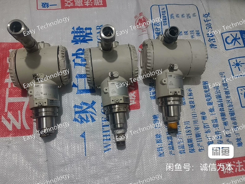
Specifications General Type: Differential Pressure Transmitter Series: ABB 266 HRH (High Pressure Differential) Output: 4–20 mA two-wire with HART communication Sensor Technology: Digital capacitive sensor with temperature compensation Measurement Performance Reference Accuracy: ±0.04% of span Repeatability: ±0.02% of span Turn-Down Ratio: Up to 100:1 Response Time: <100 ms Long-Term Stability: ±0.1% of URL over 10 years Pressure Ratings Differential Pressure Range: Configurable per PRRA7 sensor selection Static Pressure Rating: Up to 105 MPa (high-pressure HRH variant) Proof Pressure: 1.5 × static rating Overpressure Protection: Integrated mechanical system Materials & Construction Wetted Materials: Stainless steel / Hastelloy / optional alloys (per PRRA7 selection) Fill Fluid: Silicone oil or inert fluid Housing: Aluminum or stainless steel (B7TB configuration) Process Connections: High-pressure flanges or threaded adapters Electrical & Communication Power Supply: 10.5–45 VDC Output Signal: 4–20 mA + HART digital Load Resistance (HART): ≤600 Ω Local Configuration: Push-button or LCD interface (if equipped) Environmental Conditions Electronics Operating Temperature: –40 to +85 °C Process Temperature: According to sensor and fill fluid selection Humidity: 0–100% RH, non-condensing Ingress Protection: IP67 / IP68 depending on housing and terminals Vibration Resistance: Up to 10 g, 10–2000 Hz Certifications / Standards Explosion Protection: Ex ia / Ex d / Ex nA (depending on configuration) Compliance: ATEX, IECEx, PED, CE EMC & Surge Protection: Industrial-grade standards
Specifications General Type: Differential Pressure Transmitter Series: ABB 266 DSH (High Static Pressure) Output: 4–20 mA two-wire with HART communication Sensor Technology: Digital capacitive sensor with temperature compensation Measurement Performance Reference Accuracy: ±0.04% of span Repeatability: ±0.02% of span Turn-Down Ratio: Up to 100:1 Response Time: <100 ms Long-Term Stability: ±0.1% of URL over 10 years Pressure Ratings Differential Pressure Range: Configurable per SSA2B7 sensor selection Static Pressure Rating: Up to 41 MPa (DSH high-static variant) Proof Pressure: 1.5 × static rating Overpressure Protection: Integrated mechanical system Materials & Construction Wetted Materials: Stainless steel / Hastelloy / optional alloys (per SSA2B7 selection) Fill Fluid: Silicone or inert fluid Housing: Aluminum or stainless steel (EZLSB configuration) Process Connections: Flanges or threaded high-pressure adapters Electrical & Communication Power Supply: 10.5–45 VDC Output Signal: 4–20 mA + HART digital Load Resistance (HART): ≤600 Ω Local Configuration: Push-button or LCD interface (if equipped) Environmental Conditions Electronics Operating Temperature: –40 to +85 °C Process Temperature: According to sensor and fill fluid Humidity: 0–100% RH, non-condensing Ingress Protection: IP67 / IP68 depending on housing and terminals Vibration Resistance: 10 g, 10–2000 Hz Certifications / Standards Explosion Protection: Ex ia / Ex d / Ex nA (depending on configuration) Compliance: ATEX, IECEx, PED, CE EMC & Surge Protection: Industrial-grade standards
Specifications General Type: Electronic Protection Relay / Trip Unit Series: ABB S200 Series (S264) Application: Low-voltage switchgear and distribution protection Mounting: Panel or DIN rail mount Protection Functions Overcurrent Protection (Instantaneous and Time-Delayed): Configurable Short-Circuit Protection: Adjustable thresholds Earth-Fault Protection: Optional, configurable sensitivity Phase Failure / Imbalance Detection: Included Monitoring Functions: Voltage, current, active/reactive power, energy, frequency Electrical Characteristics Control Voltage: As per configuration (ES1 variant, typically 24–250 V AC/DC) Rated Current: Defined by S264 relay module Output Contacts: Trip and alarm contacts (normally open / normally closed) Communication Protocols: ABB standard communication (e.g., Modbus, PROFIBUS depending on option) Display: LCD with status indicators and menu navigation Environmental Conditions Operating Temperature: –25 to +70 °C Storage Temperature: –40 to +85 °C Humidity: 0–95% RH, non-condensing Shock & Vibration Resistance: IEC 60068 standard compliant Mechanical Housing Material: High-strength thermoplastic Ingress Protection: IP20 (panel-mounted), IP40 / IP54 options depending on enclosure Dimensions: Standard S200 relay size Certifications / Standards Standards Compliance: IEC/EN 60947-4-1, IEC/EN 60255, UL listed Safety & EMC: CE marked, IEC/EN EMC compliant
Specifications General Type: Differential Pressure Transmitter Series: ABB 266 GSH Output: 4–20 mA, two-wire with HART communication Sensor Technology: Digital capacitive differential sensor with temperature compensation Measurement Performance Reference Accuracy: ±0.04% of span (depending on calibration and range) Repeatability: ±0.02% of span Turn-Down Ratio: Up to 100:1 Response Time: <100 ms Long-Term Stability: ±0.1% URL over 10 years Pressure Ratings Differential Pressure Range: According to CKBNA1 sensor selection Static Pressure Rating: High static pressure capability (per GSH design) Proof Pressure: 1.5 × static rating Overpressure Protection: Integrated mechanical system Materials & Construction Wetted Parts: Stainless steel / Hastelloy / optional alloys (per CKBNA1) Fill Fluid: Silicone oil or inert fluid Housing: Aluminum or stainless steel (per model configuration) Process Connections: Flanges or threaded high-pressure adapters Electrical & Communication Power Supply: 10.5–45 VDC Signal: 4–20 mA + HART digital Load Resistance (HART): ≤600 Ω Local Configuration: Optional push-button or LCD interface Environmental Conditions Electronics Operating Temperature: –40 to +85 °C Process Temperature: Based on sensor and fill fluid Humidity: 0–100% RH, non-condensing Ingress Protection: IP67 / IP68 depending on housing and electrical entry Vibration Resistance: Up to 10 g, 10–2000 Hz Certifications / Compliance Explosion Protection: Ex ia / Ex d / Ex nA options depending on configuration Compliance: ATEX, IECEx, PED, CE EMC / Surge Protection: Industrial-grade standards
Specifications General Type: Differential Pressure Transmitter Series: ABB 266 HSH (High Static Pressure) Output: 4–20 mA, two-wire with HART communication Sensor Technology: Digital capacitive sensor with temperature compensation Measurement Performance Reference Accuracy: ±0.04% of span (depending on range) Repeatability: ±0.02% of span Turn-Down Ratio: Up to 100:1 Response Time: <100 ms (configurable damping available) Long-Term Stability: ±0.1% of URL over 10 years Pressure Ratings Differential Pressure Range: As per MSBA1 sensor selection Static Pressure Rating: Up to 105 MPa (1050 bar) Proof Pressure: 1.5 × static rating Overpressure Protection: Integrated mechanical overload system Materials & Construction Wetted Materials: Stainless steel / Hastelloy / optional alloys (per MSBA1 selection) Fill Fluid: Silicone or inert fluid Housing: Aluminum or stainless steel (EZTB configuration) Process Connections: High-pressure flanges or threaded adapters Electrical & Communication Power Supply: 10.5–45 VDC Output Signal: 4–20 mA + HART Load Resistance (HART): ≤600 Ω Local Configuration: Optional push-button or LCD interface Environmental Conditions Electronics Operating Temperature: –40 to +85 °C Process Temperature: According to fill fluid and sensor materials Humidity: 0–100% RH, non-condensing Ingress Protection: IP67 / IP68 depending on housing selection Vibration Resistance: 10 g, 10–2000 Hz Certifications / Compliance Explosion Protection: Ex ia / Ex d / Ex nA (per configuration) Standards Compliance: ATEX, IECEx, PED, CE EMC / Surge Protection: Industrial-grade standards
 TEL: Grace +86 13600179521
  Mail: info@hongkongeasy.com jilineasyyi@outlook.com
 Q Q:615739355
 ADDRESS:Unit 12, 20th Floor, Good View Commercial Centre, 2-16 Garden Street, Mong Kok, Hong Kong
 whats app


