
Industrial Controller
All product are in stock,guaranteed delivery within 3-7 days.


PRODUCT
PICTURE
BRAND
DESCRIBE
STOCK
DOWNLOAD
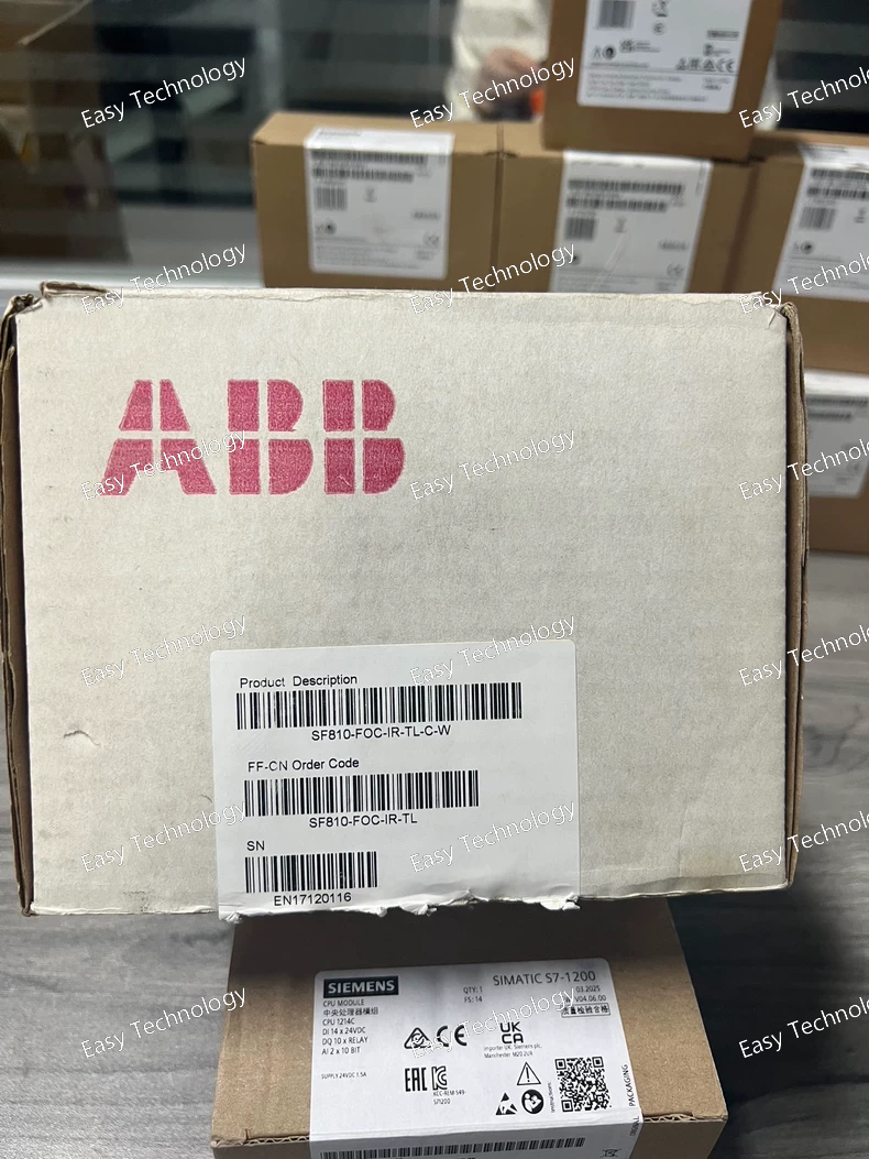
Specifications General Type: Fiber-Optic Current Sensor (FOC) Series: SF810 Model: SF810-FOC-IR-TL-C-W Application: Current measurement, monitoring, and protection Mounting: Panel or DIN rail mount, modular design Electrical Characteristics Measurement Range: 0–1000 A AC (configurable) Output Type: Fiber-optic signal proportional to measured current Accuracy Class: 0.2 / 0.5 (depending on variant) Frequency Range: 50 / 60 Hz Rated Primary Voltage: Up to 600 V AC Isolation: Full galvanic isolation via fiber-optic interface Input Type: Busbar or conductor-based measurement Mechanical & Construction Housing Material: Industrial-grade thermoplastic or epoxy Dimensions: Compact, modular for easy integration Weight: Approx. 1–2 kg Connection: Fiber-optic cable interface Protection Class: IP20 (panel mounted), optional higher IP with enclosure Environmental Conditions Operating Temperature: –25 °C to +55 °C Storage Temperature: –40 °C to +70 °C Humidity: 0–95% RH, non-condensing Standards & Certifications Standards Compliance: IEC 61869-2, IEC 60044-1 Safety & EMC: CE marked, industrial-grade EMC compliance Approvals: UL, CSA depending on region Features Contactless AC current measurement using fiber-optic and infrared (IR) technology Full galvanic isolation ensures operator and system safety Compact, modular design for easy integration in panels and switchgear High-accuracy measurement suitable for industrial and utility applications Reliable long-term performance in harsh environments Compatible with protection relays, meters, and industrial automation systems
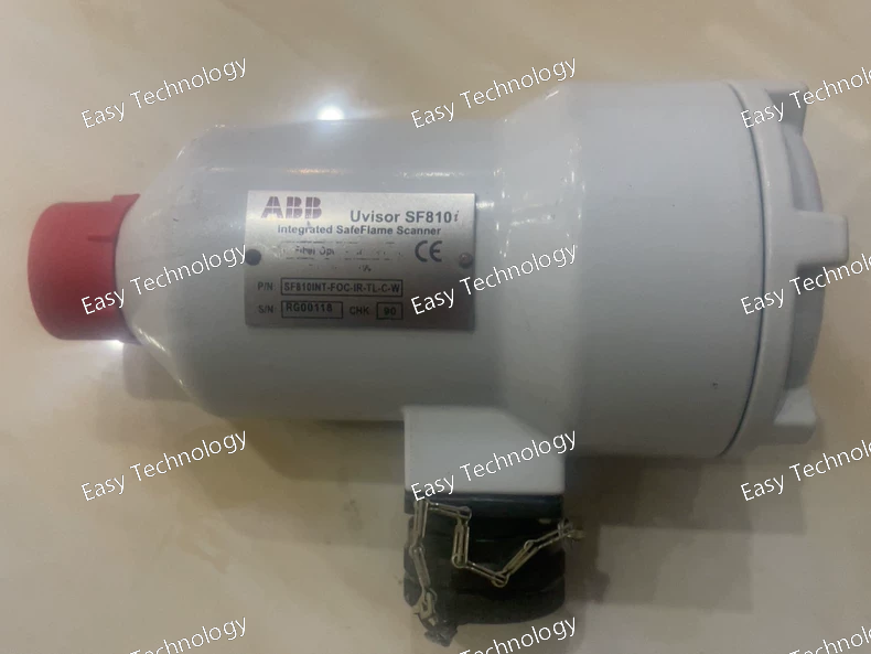
Specifications General Type: Fiber Optic Current Sensor / Uvisor SF810 Series Model: SF810 / SF810INT-FOC-IR-TL-C-W Application: Current measurement, monitoring, and protection in industrial and utility systems Mounting: Panel, DIN rail, or switchgear integration; modular design Electrical Characteristics Measurement Range: Typically 0–1000 A AC (configurable by model) Output Type: Fiber-optic signal proportional to measured current Accuracy Class: 0.2 / 0.5 (depending on variant) Frequency Range: 50 / 60 Hz Rated Primary Voltage: Up to 600 V AC (depends on installation) Isolation: Full galvanic isolation via fiber-optic interface Input Type: Direct or through busbar / conductor Mechanical & Construction Housing Material: Industrial-grade thermoplastic or epoxy resin Dimensions: Compact modular design for switchgear or panel installation Weight: Approx. 1–2 kg Connection: Fiber optic cable interface; optional integrated mounting kit Protection Class: IP20 (panel mounted); optional higher IP with enclosure Environmental Conditions Operating Temperature: –25 °C to +55 °C Storage Temperature: –40 °C to +70 °C Humidity: 0–95% RH, non-condensing Standards & Certifications Standards Compliance: IEC 61869-2, IEC 60044-1 Safety & EMC: CE marked; industrial-grade EMC compliance Approvals: UL, CSA depending on regional requirements Features High-accuracy, contactless current measurement using fiber-optic and infrared technology Full galvanic isolation ensures operator and system safety Compact, modular design for easy integration into panels and switchgear Wide measurement range suitable for industrial, commercial, and utility applications Reliable long-term performance under harsh environmental conditions Compatible with protection relays, meters, and industrial automation systems Uvisor interface provides secure and precise signal transmission
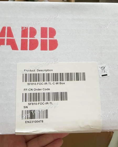
Specifications General Type: Fiber Optic Current Sensor (FOC) Series: ABB SF Model: SF810-FOC-IR-TL Application: Current measurement, monitoring, and protection Mounting: Panel or DIN rail mount, modular installation Electrical Characteristics Measurement Range: Typically 0–1000 A AC (depends on configuration) Output Type: Optical signal proportional to measured current Accuracy Class: 0.2 / 0.5 (depending on variant) Frequency Range: 50 / 60 Hz Rated Voltage: Up to 600 V AC primary circuit (depends on model) Isolation: Full galvanic isolation via fiber-optic interface Mechanical & Construction Housing Material: Industrial-grade thermoplastic or epoxy Dimensions: Compact, modular design for panel or DIN rail installation Weight: Approx. 1–2 kg Connection Type: Fiber optic cable interface Environmental Conditions Operating Temperature: –25 °C to +55 °C Storage Temperature: –40 °C to +70 °C Humidity: 0–95% RH, non-condensing Ingress Protection: IP20 (panel mounted), higher IP rating optional with enclosure Standards & Certifications Standards Compliance: IEC 61869-2, IEC 60044-1 Safety & EMC: CE marked, industrial-grade EMC compliance Approvals: UL, CSA depending on region Features Contactless current measurement using fiber-optic technology Infrared (IR) sensing for high accuracy and safety Wide measurement range suitable for industrial and utility applications Galvanic isolation ensures operator and equipment safety Compact, modular design for easy integration with protection relays and meters Suitable for power monitoring, protection, and industrial automation
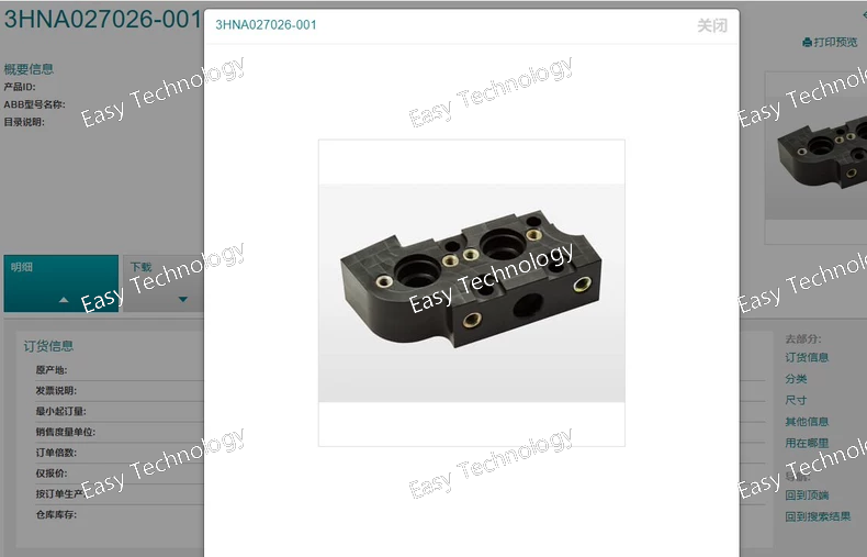
Specifications General Type: Control Relay / Auxiliary Module Series: ABB 3HNA Model: 3HNA027026-001 Application: Auxiliary signaling, interlocking, and control in low-voltage electrical systems Mounting: DIN rail or panel mount, modular installation Electrical Characteristics Rated Operational Voltage (Ue): 24–400 V AC/DC Output Contacts: Configurable NO/NC relay contacts (typical 2 NO + 2 NC) Rated Contact Current (Ie): 5–10 A depending on variant Electrical Life: 100,000 operations at rated load Coil Power Consumption: <2 W typical Mechanical & Construction Housing Material: Industrial-grade thermoplastic Mechanical Life: >1,000,000 operations Terminal Type: Screw or plug-in terminals Dimensions: Compact, modular design for panel or DIN rail installation Protection Class: IP20 (panel mounted) Environmental Conditions Operating Temperature: –25 °C to +55 °C Storage Temperature: –40 °C to +70 °C Humidity: 0–95% RH, non-condensing Standards & Certifications Standards Compliance: IEC 60947-4-1, IEC 60947-5-1 Safety & EMC: CE marked, industrial-grade EMC compliance Approvals: UL, CSA depending on region Features Modular and compact design for auxiliary control Reliable NO/NC contacts for signaling, interlocking, and control Easy snap-on or panel mounting Compatible with ABB low-voltage contactors and control devices Long mechanical and electrical service life
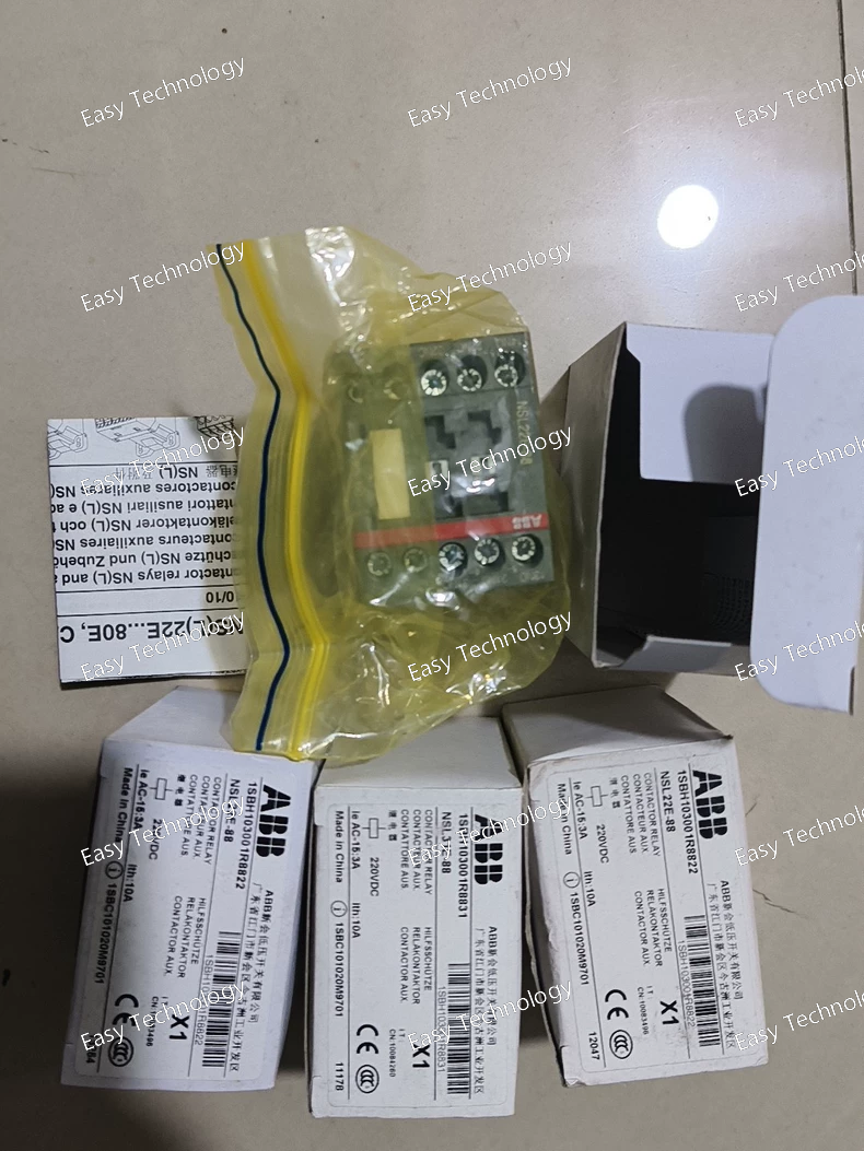
Specifications General Type: Stackable Signal Tower Light / Indicator Series: ABB NSL Model: NSL40E-88 Application: Visual signaling in industrial control and automation systems Mounting: Panel mount, pole mount, or stackable modular assembly Electrical Characteristics Rated Voltage: 24 V AC/DC, 110 V AC, or 230 V AC (depending on variant) Power Consumption: 2–6 W per module (LED), 3–5 W per module (incandescent) Light Source: LED or incandescent (depending on model) Color: Red (88 indicates red), other colors available in the NSL series Current Draw: Typically 20–50 mA (LED), higher for incandescent Mechanical & Construction Housing Material: Polycarbonate or thermoplastic Lens Type: Transparent or diffused Module Diameter: 40 mm (NSL40 series) Stackable Height: Modular, supports multiple modules stacked Protection Class: IP65 (front), IP20 (rear) Environmental Conditions Operating Temperature: –25 °C to +55 °C Storage Temperature: –40 °C to +70 °C Humidity: 0–95% RH, non-condensing Standards & Certifications Standards Compliance: IEC 60947-5-1 Safety & EMC: CE marked, industrial-grade EMC compliance Approvals: UL, CSA depending on region Features Stackable modular design for multi-level signaling High-visibility LED or incandescent options Durable construction for industrial environments Compact 40 mm module diameter for NSL40 series Easy installation and maintenance Compatible with ABB NSL series tower lights
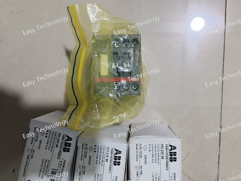
Specifications General Type: Stackable Signal Tower Light / Indicator Series: ABB NSL Model: NSL31E-88 Application: Visual signaling in industrial control, automation, and process systems Mounting: Panel mount or pole mount, stackable modular assembly Electrical Characteristics Rated Voltage: 24 V AC/DC, 110 V AC, or 230 V AC (depending on variant) Power Consumption: 1–5 W per module (LED), 3–5 W per module (incandescent) Light Source: LED or incandescent (depending on model) Color: Red (88 indicates red color), other colors available in the NSL series Current Draw: Typically 20–40 mA (LED), higher for incandescent Mechanical & Construction Housing Material: Polycarbonate or thermoplastic Lens Type: Transparent or diffused for clear visibility Module Diameter: Standard 31 mm for NSL31 series Stackable Height: Modular, up to several modules stacked Protection Class: IP65 (front), IP20 (rear) Environmental Conditions Operating Temperature: –25 °C to +55 °C Storage Temperature: –40 °C to +70 °C Humidity: 0–95% RH, non-condensing Standards & Certifications Standards Compliance: IEC 60947-5-1 Safety & EMC: CE marked, industrial-grade EMC compliance Approvals: UL, CSA depending on region Features Stackable modular design for multi-level signaling High-visibility LED or incandescent options Durable and robust construction for industrial environments Compact module size compatible with NSL31 series Easy installation and maintenance
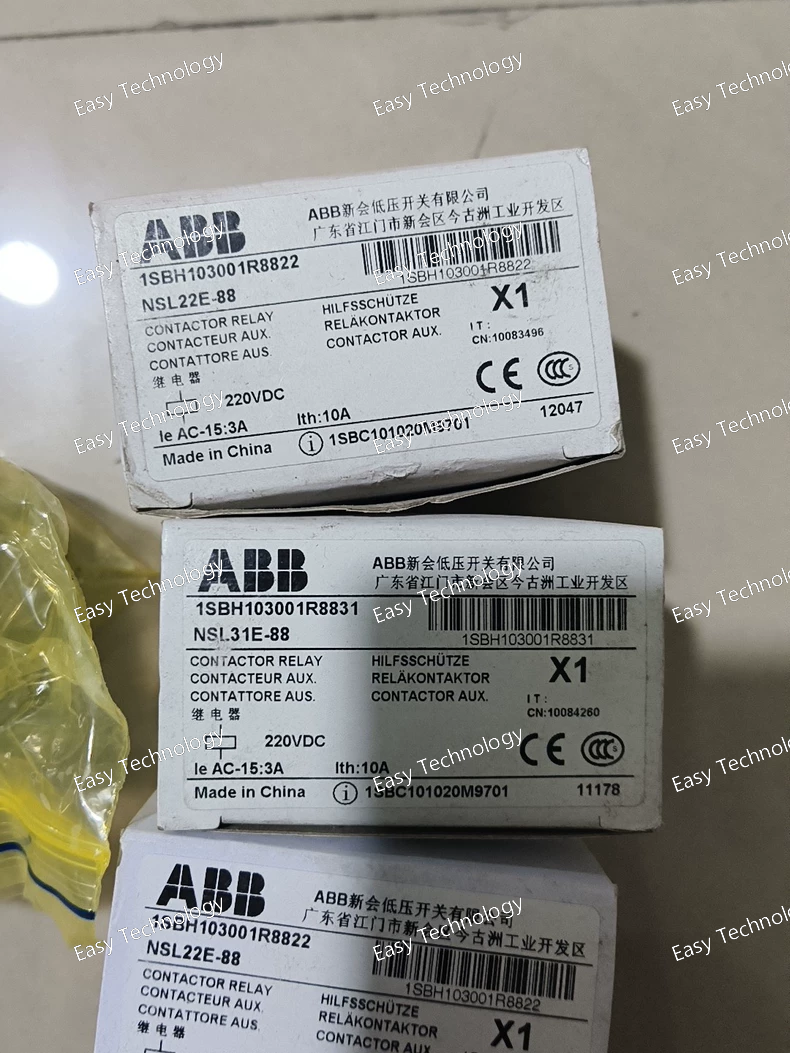
Specifications General Type: Signal Lamp / Indicator Light Series: ABB NSL Model: NSL22E-88 Application: Visual status indication in control panels and industrial systems Mounting: Front panel mount, standard cutout Electrical Characteristics Rated Voltage: 24 V AC/DC, 110 V AC, or 230 V AC (depending on variant) Power Consumption: 1–3 W (LED), 3–5 W (incandescent) Light Source: LED or incandescent (depending on model) Color: Red (88 indicates red color), other colors may be available in series Current Draw: Typically 20–30 mA (LED), higher for incandescent Mechanical & Construction Housing Material: Polycarbonate or thermoplastic Lens Type: Transparent or diffused for clear visibility Mounting Hole Diameter: Standard 22 mm cutout Dimensions: Compact and standardized for NSL series Protection Class: IP65 (front panel), IP20 (rear) Environmental Conditions Operating Temperature: –25 °C to +55 °C Storage Temperature: –40 °C to +70 °C Humidity: 0–95% RH, non-condensing Standards & Certifications Standards Compliance: IEC 60947-5-1 Safety & EMC: CE marked, industrial-grade EMC compliance Approvals: UL, CSA depending on region Features Clear visual indication for machine/process status Robust and durable construction for industrial use Compact design suitable for standard 22 mm panel cutouts Available in multiple colors and light sources (LED/incandescent) Easy installation and maintenance
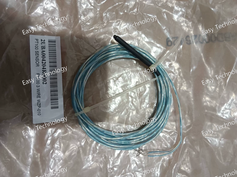
Specifications General Type: PLC I/O Module Series: ABB 2UBA Model: 2UBA004204R0002 Application: Digital input/output interface for PLC systems Mounting: DIN rail or rack mount, modular installation Electrical Characteristics Input Voltage: 24 V DC Input Type: Digital, sinking or sourcing (depending on variant) Output Type: Relay / transistor (digital switching output) Number of Channels: 4 inputs, 4 outputs Rated Current per Output: 0.5–2 A (depending on module type) Isolation: Optical or galvanic isolation between input/output and logic Mechanical & Construction Housing Material: Industrial-grade thermoplastic Dimensions: Compact modular design for PLC racks Terminal Type: Screw terminals or plug-in connectors Weight: Approx. 0.2–0.5 kg Environmental Conditions Operating Temperature: 0 °C to +55 °C Storage Temperature: –25 °C to +70 °C Humidity: 5–95% RH, non-condensing Standards & Certifications Standards Compliance: IEC 61131-2, UL 61010 Safety & EMC: CE marked, industrial-grade EMC compliance Approvals: UL, CSA depending on region Features Compact and modular design for PLC racks Reliable digital input/output for industrial control High-speed response for automation and process control Galvanic or optical isolation for system protection Compatible with ABB PLC controllers and automation systems
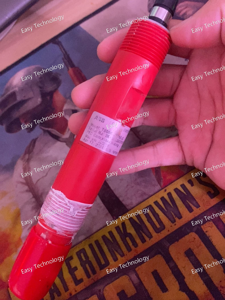
Specifications General Type: Molded Case Circuit Breaker (MCCB) Series: ABB T-series Model: TB556J2E150JS Application: Overcurrent and short-circuit protection of electrical circuits Mounting: Panel or DIN rail mount Electrical Characteristics Rated Operational Voltage (Ue): 415 / 690 V AC Rated Current (In): 150 A Number of Poles: 3-pole Breaking Capacity: 50 kA at 415 V AC Trip Unit Type: Thermal-magnetic (adjustable) Rated Frequency: 50 / 60 Hz Control Type: Manual toggle for ON/OFF Mechanical & Construction Housing Material: Thermoset / industrial-grade polymer Mechanical Life: 10,000 operations Electrical Life: 4,000 operations at rated load Terminal Type: Screw terminals for busbar or cable connection Dimensions: Compact design for panel installation Protection Class: IP20 (panel mounted) Environmental Conditions Operating Temperature: –25 °C to +55 °C Storage Temperature: –40 °C to +70 °C Humidity: 0–95% RH, non-condensing Standards & Certifications Standards Compliance: IEC 60947-2, UL 489 Safety & EMC: CE marked, industrial-grade EMC compliance Approvals: UL, CSA, IEC certified Features High breaking capacity for reliable circuit protection Adjustable thermal-magnetic trip unit for precise protection Compact design suitable for panels and motor control centers Robust housing and terminals for industrial environments Manual ON/OFF toggle with clear indication
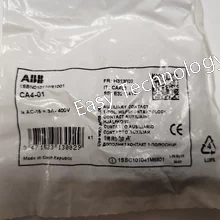
Specifications General Type: Selector / Control Switch Series: ABB CA Model: CA4-01 Application: Manual switching and control of electrical circuits Mounting: Panel mount, front panel cutout Electrical Characteristics Rated Operational Voltage (Ue): 600 V AC max Rated Operational Current (Ie): 10 A Number of Poles: 1-pole or 2-pole depending on variant Contact Configuration: SPDT or DPDT (depending on model) Insulation Voltage (Ui): 660 V Mechanical Life: 50,000 operations typical Electrical Life: 10,000 operations at rated load Mechanical & Construction Housing Material: Industrial-grade thermoplastic Actuator: Rotary knob or lever with clear ON/OFF indication Terminal Type: Screw terminals Dimensions: Standard panel cutout compatible with CA series Protection Class: IP40 (front), IP20 (rear) Environmental Conditions Operating Temperature: –25 °C to +55 °C Storage Temperature: –40 °C to +70 °C Humidity: 0–95% RH, non-condensing Standards & Certifications Standards Compliance: IEC 60947-3, UL 508 Safety & EMC: CE marked Approvals: UL, CSA depending on region Features Durable and reliable manual control switch Clear position indication for safe operation Compact design suitable for panel installation Compatible with industrial motor control and automation systems Flexible contact configurations (SPDT / DPDT)
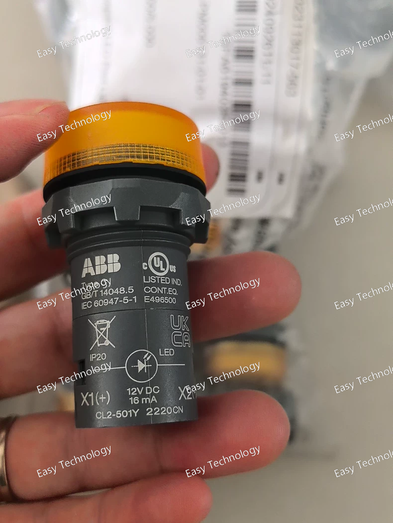
Specifications General Type: Current Transformer (CT) Series: ABB CL2 Model: CL2-501Y Application: Current measurement, monitoring, and protection Mounting: Panel or busbar mount Electrical Characteristics Primary Current Rating: 500 A Secondary Current Rating: 5 A (standard) Rated Frequency: 50 / 60 Hz Accuracy Class: 0.5 / 1.0 (depending on version) Rated Burden: Up to 10 VA (depends on application) Insulation Level: 0.72 kV / 1.2 kV (depending on version) Mechanical & Construction Housing Material: Epoxy resin or thermoplastic Terminal Type: Screw terminals or busbar connection Dimensions: Compact and easy to install Weight: Approx. 0.5–1 kg Environmental Conditions Operating Temperature: –25 °C to +55 °C Storage Temperature: –40 °C to +70 °C Humidity: 0–95% RH, non-condensing Ingress Protection: IP20 (panel mounted) Standards & Certifications Standards Compliance: IEC 61869-2, IEC 60044-1 Safety Approvals: CE marked, industrial-grade standards Applications: Compatible with ABB protection relays, meters, and monitoring devices Features High accuracy for protection and metering applications Compact and robust design for easy installation Reliable long-term performance in industrial and commercial environments Suitable for integration with relays, meters, and monitoring systems
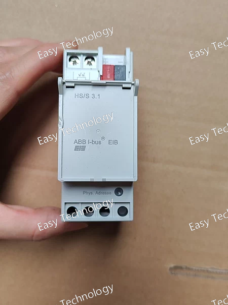
Specifications General Type: Safety / Manual Disconnect Switch Series: ABB HS/S Model: 3.1 Application: Isolation and manual switching of low-voltage circuits Mounting: Panel mount, front cutout Electrical Characteristics Rated Operational Voltage (Ue): 690 V AC max Rated Operational Current (Ie): 32–63 A (depending on variant, typical for 3.1) Number of Poles: 3-pole Short-Circuit Rating: 10 kA (depends on model and installation) Control Type: Manual rotary or toggle handle Mechanical & Construction Housing Material: Industrial-grade thermoplastic or metal Actuator: Rotary handle with ON/OFF position indication Mechanical Life: 10,000 operations Terminal Type: Screw or busbar connection Dimensions: Compact design for panel installation Protection Class: IP20 (panel mounted), IP65 optional enclosure Environmental Conditions Operating Temperature: –25 °C to +55 °C Storage Temperature: –40 °C to +70 °C Humidity: 0–95% RH, non-condensing Standards & Certifications Standards Compliance: IEC 60947-3, UL 508 Safety & EMC: CE marked Approvals: UL, CSA depending on region Features Robust and durable design for industrial safety applications Clear ON/OFF position indication for safe operation Manual rotary handle for quick isolation of circuits Compact form factor suitable for panel or switchboard installation Compatible with auxiliary modules for signaling or interlocking
 TEL: Grace +86 13600179521
  Mail: info@hongkongeasy.com jilineasyyi@outlook.com
 Q Q:615739355
 ADDRESS:Unit 12, 20th Floor, Good View Commercial Centre, 2-16 Garden Street, Mong Kok, Hong Kong
 whats app


