
Industrial Controller
All product are in stock,guaranteed delivery within 3-7 days.


PRODUCT
PICTURE
BRAND
DESCRIBE
STOCK
DOWNLOAD
Technical Parameters Parameter Value / Detail Model / Part Number SDCS‑IOB‑23 Function External isolated digital I/O interface board for ABB drives / control units Supply / Signal Voltage 230 VAC I/O Channels Digital inputs and outputs; number of points depends on configuration Isolation / Insulation Galvanically isolated inputs/outputs to improve noise immunity and safety Compatibility Add-on I/O board for ABB drive systems to replace internal I/O and provide isolated external I/O Environmental / Protection Options Coated version available for enhanced robustness against dust, moisture, and electrical noise Typical Applications Industrial automation: connecting sensors and actuators, external I/O expansion for drives, process control, system integration in harsh environments
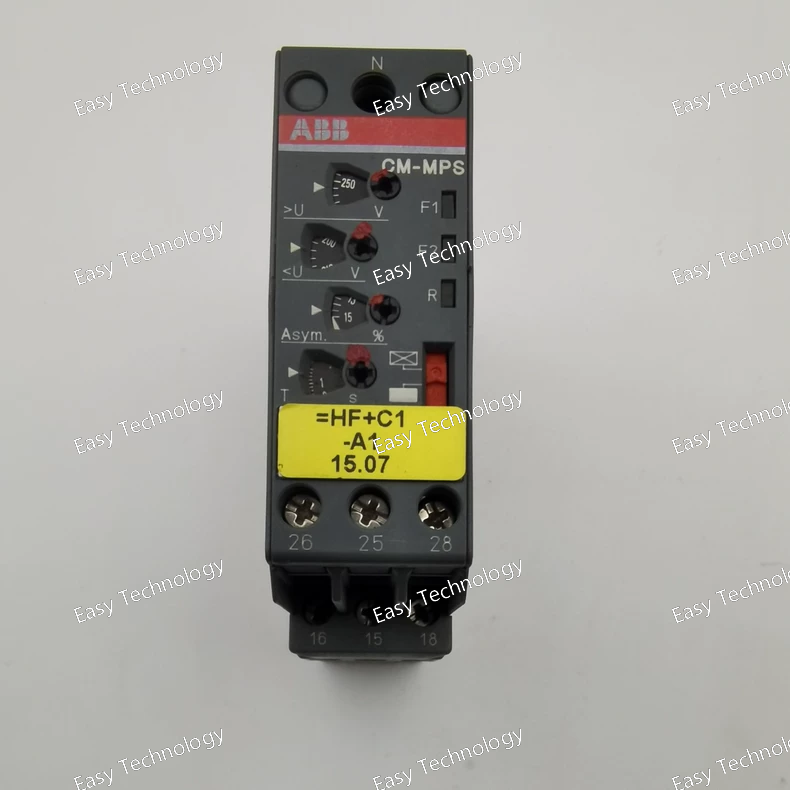
Technical Parameters Parameter Value / Range Rated Supply Voltage 180–280 V AC (line-to-neutral) Frequency 50 / 60 Hz Monitored Conditions Phase failure, Phase sequence, Over-voltage, Under-voltage, Phase unbalance (optional: neutral interruption) Adjustable Thresholds Over-/under-voltage and asymmetry (unbalance) thresholds adjustable Tripping Delay Start-up delay 200 ms; tripping delay adjustable 0.1–30 s Output Contacts 2 changeover contacts (SPDT) Contact Rating AC‑12 (230 V): 4 A; AC‑15 (230 V): 3 A; DC‑12 (24 V): 4 A; DC‑13 (24 V): 2 A; Minimum 24 V / 10 mA Insulation / Surge Withstand Input → output: 600 V; output circuits: 300 V; Impulse withstand: input 6 kV, output 4 kV Protection Housing: IP50; Terminals: IP20; Pollution degree 3; Overvoltage category III Wiring / Terminals Screw-type, double-chamber cage connection; accepts rigid or flexible wire up to 4 mm² Mounting / Dimensions / Weight DIN-rail (TH35‑7.5 or TH35‑15); 22.5 mm × 85.6 mm × 103.7 mm; ~0.146 kg Operating / Storage Temperature Operating: −25 °C … +60 °C; Storage: −40 °C … +85 °C Indicators 3 LEDs for supply and fault status Standards / Approvals Conforms to IEC/EN/UL/CSA standards for measuring and monitoring relays
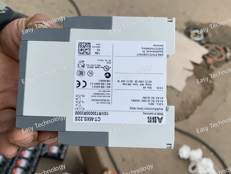
Technical Parameters Parameter Value / Range Control Supply Voltage (Us) 24–48 V DC or 24–240 V AC Time Range (adjustable) 0.05 s – 300 h (via 2 × 10 time ranges) Timing Functions Asymmetrical ON-/OFF‑delay, Impulse ON/OFF, Pulse generator (ON or OFF start), Single pulse generator, ON/OFF function Output Contacts 2 c/o (SPDT) contacts Contact Rating 250 V / 4 A (AC), 24 V / 4 A (DC) for resistive loads Minimum Switching Capacity 12 V / 10 mA Insulation / Surge Withstand Rated insulation voltage: input vs output = 500 V; output circuits = 300 V. Rated impulse withstand voltage: input circuit 4 kV; outputs 4 kV Connection Terminals Screw terminals, double-chamber cage type; accepts rigid or flexible wire (0.5–4 mm²) Dimensions (W × H × D) 22.5 mm × 85.6 mm × 103.7 mm Weight ~0.142 kg Mounting DIN‑rail (TH35‑15 or TH35‑7.5 per IEC 60715) Operating Temperature –25 °C … +60 °C Degree of Protection Housing: IP50, Terminals: IP20 Standards / Approvals IEC/EN 61812‑1, UL 508, CAN/CSA C22.2 No.14, CE (RoHS compliant) Other Features Two status-indication LEDs (control supply/timing & output relay), possibility to seal timer settings with a transparent cover
Technical Specifications Parameter Value / Description Product / Model CT‑MVS.23S multifunction electronic time relay Part Number 1SVR730021R2300 Control / Supply Voltage (Us) 380–440 V AC Time Range 0.05 seconds … 300 hours (selectable among 10 ranges) Timing Functions Supported ON‑delay (delay‑on‑make), OFF‑delay (delay‑on‑break), symmetrical ON/OFF delay, Impulse‑ON, Impulse‑OFF, Pulse generator, Star‑Delta change‑over (star‑triangle), Pulse former, Basic ON/OFF (instant) Output Contacts 2 × change‑over contacts (2 C/O, SPDT) Contact Ratings 250 V AC / 4 A (general/AC‑12); 230 V AC / 3 A (inductive / motor‑control AC‑15); 24 V DC / 4 A (DC‑12); 24 V DC / 2 A (DC‑13) Minimum Switching Capacity 12 V, 10 mA (i.e. supports small‑signal loads) Insulation & Withstand Ratings Input/Output rated for 500 V insulation voltage; output circuits rated up to 300 V. Impulse withstand / surge withstand per standard. Wiring / Terminals Screw‑terminal (double‑chamber cage type); wire capacity: flexible up to 2.5 mm² (with ferrule), rigid up to 4.0 mm²; tightening torque 0.6–0.8 N·m. Mounting / Dimensions DIN‑rail (TH35) mountable. Module width: 22.5 mm; Overall dimensions: ~22.5 mm (W) × 85.6 mm (H) × 103.7 mm (D). Operating / Environmental Conditions Ambient temperature: –25 °C … +60 °C; Storage: –40 °C … +85 °C. Pollution degree 3, Overvoltage category III. Housing protection: IP50; Terminals: IP20. Durability Electrical durability (AC‑12): ~100,000 cycles; Mechanical life up to ~30,000,000 operations. Other Features Double change‑over contacts for flexible wiring logic; ten selectable time‑ranges; front‑face selector and fine‑adjust potentiometer for time setting; optional sealable transparent cover to protect settings; control input is voltage‑related (non-floating trigger).
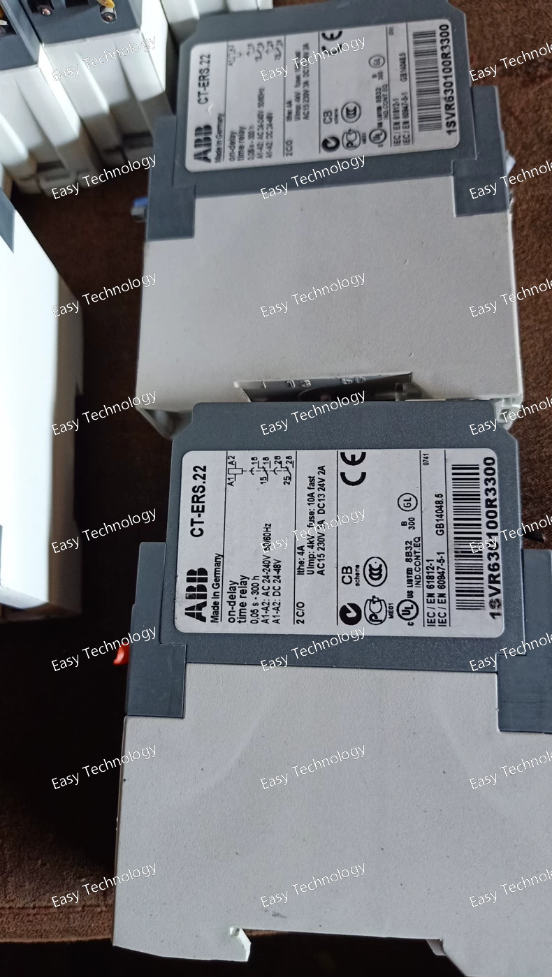
Technical Specifications Parameter / Item Value / Description Product / Model CT‑ERS.22 ON‑delay Timer Relay Part Number 1SVR630100R3300 Supply / Control Voltage (Us) 24–48 V DC or 24–240 V AC (50/60 Hz) Function (Timer Type) Single‑function ON‑delay (delay‑on‑make) Time Range (adjustable) Ten selectable ranges: 0.05 s … 300 h (e.g. 0.05–1 s, 0.15–3 s, 0.5–10 s, 1.5–30 s, 5–100 s, 15–300 s, 1.5–30 min, 15–300 min, 1.5–30 h, 15–300 h) Reset / Recovery Time (after supply removal) < 80 ms Output Contacts 2 × change‑over contacts (SPDT / 2 c/o) Contact Ratings 250 V AC / 4 A (for general AC‑12 loads) 230 V AC / 3 A (inductive / motor‑control AC‑15 loads) 24 V DC / 4 A (DC‑12) 24 V DC / 2 A (DC‑13) Minimum Switching Capacity 12 V / 10 mA (suitable for low‑power / signal loads) Connection / Terminal Type Double‑chamber cage screw‑terminals (wired conductors: flexible 0.5–2.5 mm² or rigid up to 4 mm²) Module / Mounting Dimensions Width: 22.5 mm; nominal module; DIN‑rail mount (standard TH35); easy snap‑on / removal Overall Dimensions (W × H × D) 22.5 mm × 85.6 mm × 103.7 mm Net Weight ~ 0.121 kg Ambient Operating Temperature –25 °C … +60 °C Storage Temperature Range –40 °C … +85 °C Insulation & Withstand Ratings Rated insulation up to 500 V (input‑output); output circuit rating up to 300 V; impulse withstand voltage specified for output circuits; pollution degree 3; overvoltage category III Certifications / Approvals Compliant with IEC/EN 61812‑1; UL 508 / CAN/CSA C22.2 No.14; CE, CB, CCC etc.; housing material UL 94 V‑0 rated Indicators / Controls Front‑face rotary selector for time-range, internal fine‑adjust potentiometer for delay time; 2 LEDs for status indication (power / timing and output relay status) Other Features Wide supply‑voltage flexibility (AC or DC), selectable time-range, compact DIN‑rail mounting, screw‑terminal connections, dual SPDT outputs — suitable for broad range of timing and control applications
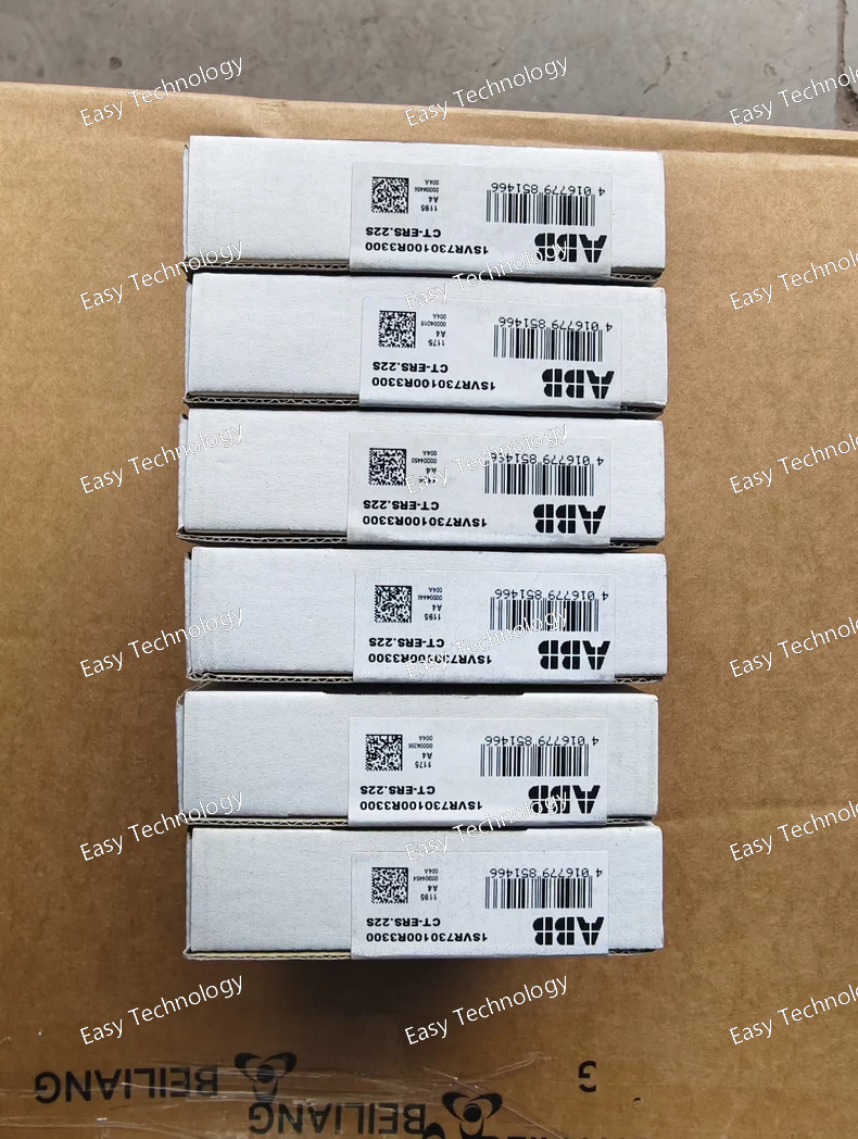
Technical Specifications Parameter / Item Value / Description Function / Timer Type ON‑delay (delay‑on‑make) single‑function electronic timer relay Part Number 1SVR730100R3300 Supply / Control Voltage (Us) 24 … 48 V DC or 24 … 240 V AC (50/60 Hz) Time Range (adjustable) 0.05 s … 300 h (ten selectable ranges) Recovery / Reset Time < 80 ms after supply removal Output Contacts 2 × change‑over contacts (SPDT / 2 c/o) Contact Ratings 250 V AC / 4 A (general load, AC‑12) 230 V AC / 3 A (inductive / motor‑control, AC‑15) 24 V DC / 4 A (DC‑12) 24 V DC / 2 A (DC‑13) Minimum Switching Capacity 12 V, 10 mA (i.e. small‑signal loads supported) Connection / Terminals Screw‑terminal type (double‑chamber cage connection); wiring capacity: flexible 0.5–2.5 mm², rigid up to 4 mm²; tightening torque 0.6–0.8 N·m Mounting DIN‑rail (e.g. TH35) snap‑on mounting — tool‑free installation / removal Module Width 22.5 mm Dimensions (W × H × D) 22.5 mm × 85.6 mm × 103.7 mm Net Weight ~ 0.121 kg Ambient Operating Temperature –25 °C … +60 °C Storage Temperature Range –40 °C … +85 °C Insulation / Impulse Withstand / Protection Rated insulation up to 500 V (input‑output); output circuits rated 300 V; impulse withstand on circuits; Housing rating IP50, terminals IP20; Pollution degree 3; Overvoltage category III Approvals / Compliance Meets standards: IEC/EN 61812‑1; UL 508, CAN/CSA C22.2 No.14; CE, CB, CCC, RoHS, etc. Adjustment / User Controls Front‑face time‑range selector + fine‑adjust potentiometer for time; optional sealable transparent cover to prevent unauthorized changes; status indication via LED(s)
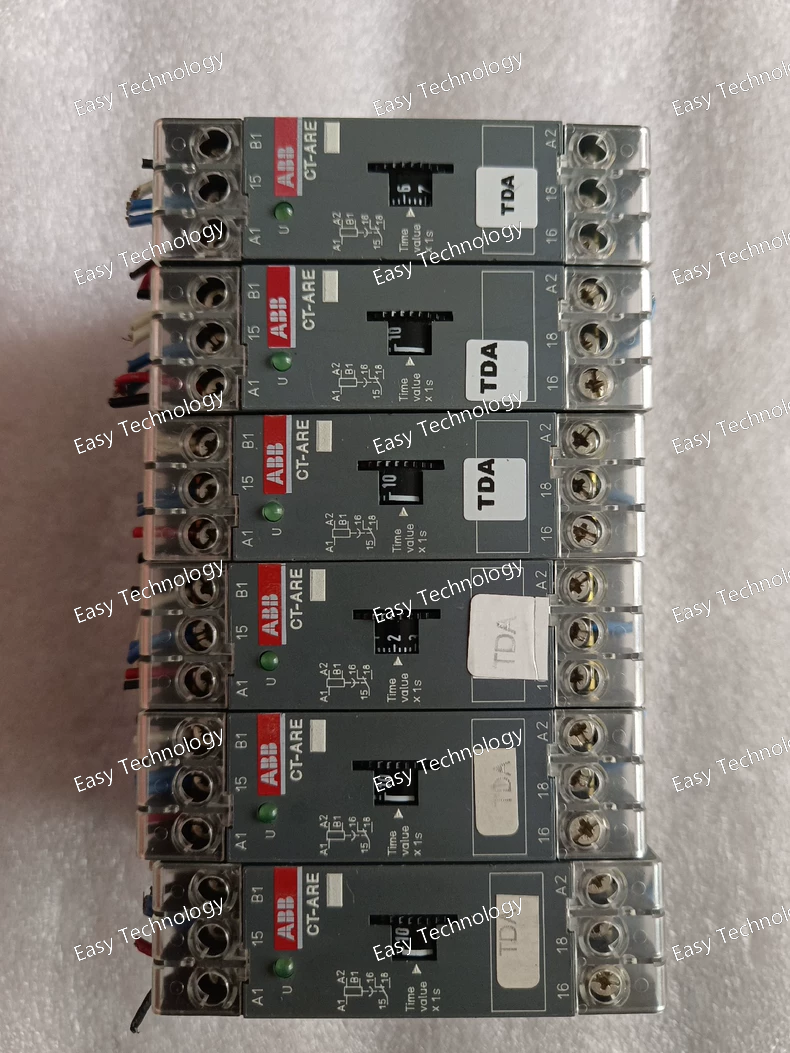
Technical Specifications Parameter / Item Value / Description Function Single‑function OFF‑delay timer (true delay on break) Control / Supply Voltage (Us) 24 V AC/DC or 220–240 V AC (for versions 24 V AC/DC & 220–240 V AC) or 110–130 V AC (alternate version) Time Range Options 0.1 … 10 s or 0.3 … 30 s (depending on version) Output Contacts 1 × change‑over (SPDT, 1 C/O) Output Contact Rating 250 V AC, 4 A (AC‑12 general load) Rated Operational Current — Output AC‑12: 4 A @ 230 V AC AC‑15 (inductive/motor-control): 3 A @ 230 V AC DC‑12: 4 A @ 24 V DC DC‑13: 2 A @ 24 V DC Width / Size / Mounting 22.5 mm wide module; DIN‑rail (TH35) mountable; suitable for side‑by‑side mounting Terminal Type / Wiring Screw‑terminal, double‑chamber cage connection; flexible wire or rigid wire per spec Minimal Energizing Time 200 ms (control supply must be applied at least this long to start timing properly) LED Indication Green LED indicates supply present / relay energized Approvals / Compliance IEC/EN 61812‑1; UL 508 / CAN/CSA C22.2 No.14; CE, CB, CCC, GOST etc. depending on version Typical Use Cases Delay‑off control of lights, motors, contactors; sequencing; ensuring minimum run‑on times; automation control tasks; simple on‑break delay logic
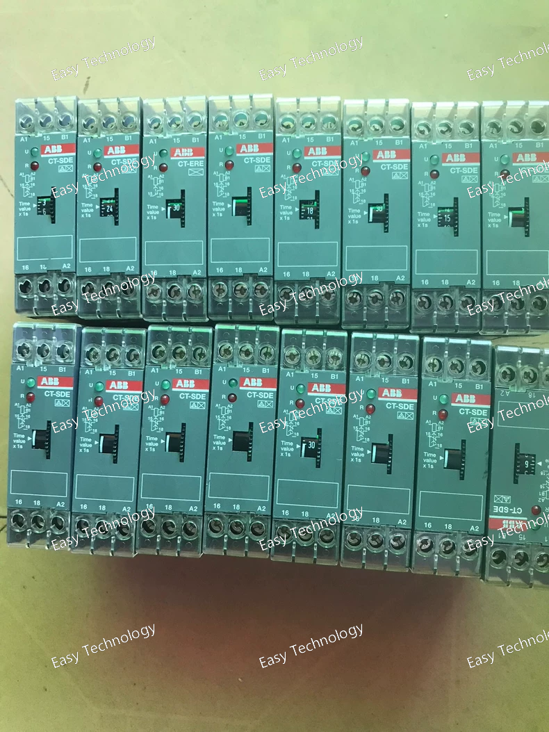
Technical Specifications Parameter / Item Value / Description Product / Model Name CT‑SDE star‑delta time relay Part Number 1SVR550217R4100 Function / Purpose Star‑delta (star‑triangle) time‑delay relay for motor start sequencing Time Range (adjustable) 0.3 … 30 seconds Control / Supply Voltage (Us) 220 … 240 V AC or 24 V AC / DC Outputs / Contacts 1 × normally‑open (NO) contact + 1 × normally‑closed (NC) contact (SPDT / change‑over) Contact Ratings AC‑12: 250 V / 4 A; AC‑15: 230 V / 3 A; DC‑12: 24 V / 4 A; DC‑13: 24 V / 2 A Terminal / Connection Type Screw‑terminals, suitable for fine-strand or rigid conductors Mounting DIN‑rail (TH35) snap‑on mounting, any orientation Dimensions (W × H × D) 22.5 mm × 78 mm × 78.5 mm Net Weight ~0.077 kg Housing / Protection Housing IP50; Terminals IP20; Plastic UL‑94 V‑0 / V‑2 rated Electrical Connection / Wire Capacity Fine-strand with ferrule: 2 × 0.75–1.5 mm²; Rigid conductors: 2 × 0.75–1.5 mm² Terminal Screw Torque 0.6–0.8 N·m Standards & Certifications IEC/EN 61812‑1, CAN/CSA C22.2 No.14, UL 508; RoHS compliant
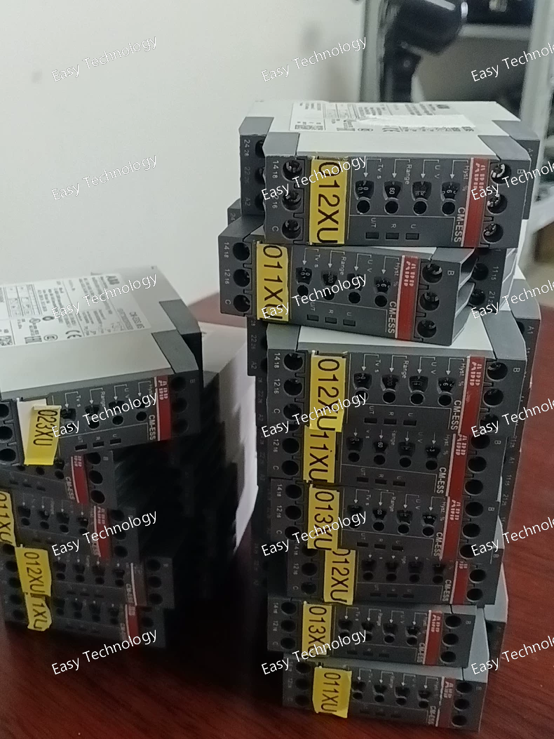
Technical Specifications Specification / Item Value / Description Product / Model CM‑ESS.MS single‑phase voltage monitoring relay Part Number 1SVR730830R0500 Function Over‑ or under‑voltage monitoring Rated Control / Supply Voltage (Us) 24 … 240 V AC or DC Measuring Range (Voltage) 3–30 V, 6–60 V, 30–300 V, 60–600 V AC/DC (selectable) Output Contacts 2 × change‑over (SPDT) Contact Ratings AC‑12: 250 V / 4 A; AC‑15: 230 V / 3 A; DC‑12: 24 V / 4 A; DC‑13: 24 V / 2 A Minimum Switching Capacity 24 V, 10 mA Trip / Delay Settings Start-up delay: 0 s (instant) Trip delay adjustable: 0.1 … 30 s or instantaneous Hysteresis / Threshold Adjustment Adjustable: 3 … 30% of threshold Terminal / Connection Type Screw terminals (double‑chamber cage‑connection) Mounting DIN‑rail (TH35) Insulation / Protection Measuring/output insulation: up to 600 V; Output: 250 V; Housing IP50; Terminals IP20; Pollution degree 3; Overvoltage category III Operating Temperature –20 °C … +60 °C Storage Temperature –40 °C … +85 °C Dimensions (W × H × D) 22.5 mm × 85.6 mm × 103.7 mm Net Weight ~0.154 kg Mechanical / Electrical Life Electrical: 100,000 cycles; Mechanical: 30,000,000 operations Wire Connection Capacity Flexible 0.5–2.5 mm²; Rigid 0.5–4 mm²; Torque 0.6–0.8 N·m Output Circuit Maximum Voltage 300 V AC
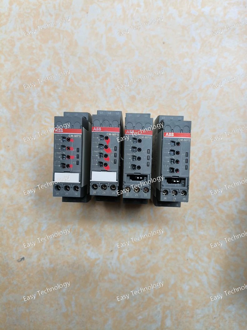
Technical Specifications Parameter / Item Value / Description Product / Model CM‑MPS.41S three‑phase monitoring relay Part Number 1SVR730884R3300 Monitored / Supply Voltage (L–L) 300 … 500 V AC, 50/60 Hz Functions / Monitoring Phase loss detection; Phase sequence (rotation) monitoring; Over‑voltage detection; Under‑voltage detection; Phase unbalance detection Output Contacts 2 × change‑over contacts (SPDT / 2 c/o) Contact Rating Up to 250 V AC / 4 A (AC‑12 general load) 230 V AC / 3 A (AC‑15 inductive / motor‑control load) 24 V DC / 4 A (DC‑12) 24 V DC / 2 A (DC‑13) Minimum Switching Capacity 24 V / 10 mA (suitable for small control signals) Trip / Delay Settings Startup / Power-on delay: 200 ms Trip delay (ON or OFF): instantaneous (0 s) or adjustable 0.1 … 30 s Terminal / Connection Type Screw‑terminal (double‑chamber cage connection) Dimensions (W × H × D) 22.5 mm × 85.6 mm × 103.7 mm Net Weight ~ 0.14 kg Insulation / Impulse Withstand Voltage Input/Output insulation: 600 V; Impulse withstand: Input 6 kV, Output 4 kV Protection / Housing Rating Housing: IP50; Terminals: IP20 Operating Ambient Temperature –25 °C … +60 °C Storage Temperature Range –40 °C … +85 °C Standards & Certifications Compliant with IEC/EN 60255‑27, IEC/EN 61000‑6-2 / 61000‑6-3, CAN/CSA C22.2 No.14, UL 508; UL/CSA contact rating B300 Pollution degree 3, Overvoltage category III

Technical Specifications Specification / Item Value / Description Product Type / Model CT‑MFS.21S multifunction electronic time relay Part Number 1SVR730010R0200 Rated Control Supply Voltage (Us) 24 … 240 V AC or DC Timing Range 0.05 seconds … 300 hours (selectable) Timing Functions ON‑delay, OFF‑delay, impulse‑ON, impulse‑OFF, symmetrical ON/OFF delay, flasher, pulse former, star‑delta changeover, accumulative ON‑delay, ON/OFF function Outputs 2 × change‑over contacts (2 c/o, SPDT) Contact Ratings Up to 250 V AC / 4 A Terminal / Connection Type Screw‑terminal, double‑chamber cage connection Optional Features Remote potentiometer connection for fine time adjustment; second contact configurable as instantaneous; sealable transparent cover available Mounting DIN‑rail (TH35) or panel/rail mounting Ambient / Operating Temperature –40 °C … +60 °C Storage Temperature –40 °C … +85 °C Wiring Capacity Flexible cable: 1 × 0.5–2.5 mm²; Rigid cable: 1 × 0.5–4 mm² Contact Utilization / Duty Pilot duty B300; suitable for general-purpose switching within rating Width / Footprint 22.5 mm Certifications / Compliance CE, UL/CSA, RoHS compliant Typical Applications Flexible timing functions for motors, pumps, fans, lighting, and machinery sequences Automation control panels and general-purpose time-based control Sequential control, delayed switching, safety delays, and flasher applications Slim DIN-rail mount design for compact installation in control cabinets Remote potentiometer for on-the-fly adjustment without opening the enclosure Dual SPDT outputs for main load control and auxiliary signaling or logic
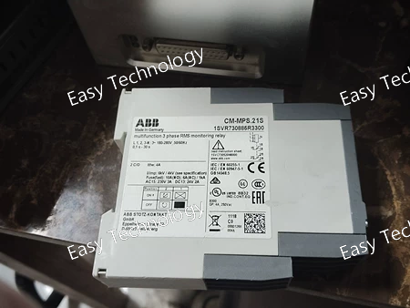
Technical Specifications Specification Value / Description Product / Model CM-MPS.21S three-phase monitoring relay Part Number 1SVR730885R3300 Function Phase failure detection, phase sequence monitoring, over-/under-voltage detection, phase unbalance detection, interrupted-neutral detection Measured / Supply Voltage 3 × 180 … 280 V AC (phase-to-neutral) Frequency 50 / 60 Hz Output Contacts 2 × change-over (SPDT / DPDT) contacts Contact Ratings AC-12 (general load): 4 A @ 230 V AC AC-15 (inductive/motor-control load): 3 A @ 230 V AC DC-12: 4 A @ 24 V DC DC-13: 2 A @ 24 V DC Switching Capacity (minimum) 24 V, 10 mA Trip / Delay Settings Start-up delay: 200 ms Trip delay adjustable: 0.1 … 30 s Selectable ON-delay or OFF-delay Connection / Terminals Screw terminals; flexible 1×0.5–2.5 mm², rigid 1×0.5–4 mm² Mounting DIN-rail (TH35) or panel mounting Dimensions (W × H × D) 22.5 mm × 85.6 mm × 103.7 mm Net Weight ~0.146 kg Ambient / Operating Temperature –25 … +60 °C Storage Temperature –40 … +85 °C Insulation / Impulse Withstand Input/output insulation 600 V; impulse withstand: input 6 kV, output 4 kV Protection / Standards Housing: IP50; Terminals: IP20; IEC/EN 60255-27; UL/CSA B300 contact rating Functions Phase monitoring, adjustable thresholds, adjustable trip delay, ON/OFF delay selection
 TEL: Grace +86 13600179521
  Mail: info@hongkongeasy.com jilineasyyi@outlook.com
 Q Q:615739355
 ADDRESS:Unit 12, 20th Floor, Good View Commercial Centre, 2-16 Garden Street, Mong Kok, Hong Kong
 whats app


