
Industrial Controller
All product are in stock,guaranteed delivery within 3-7 days.


PRODUCT
PICTURE
BRAND
DESCRIBE
STOCK
DOWNLOAD
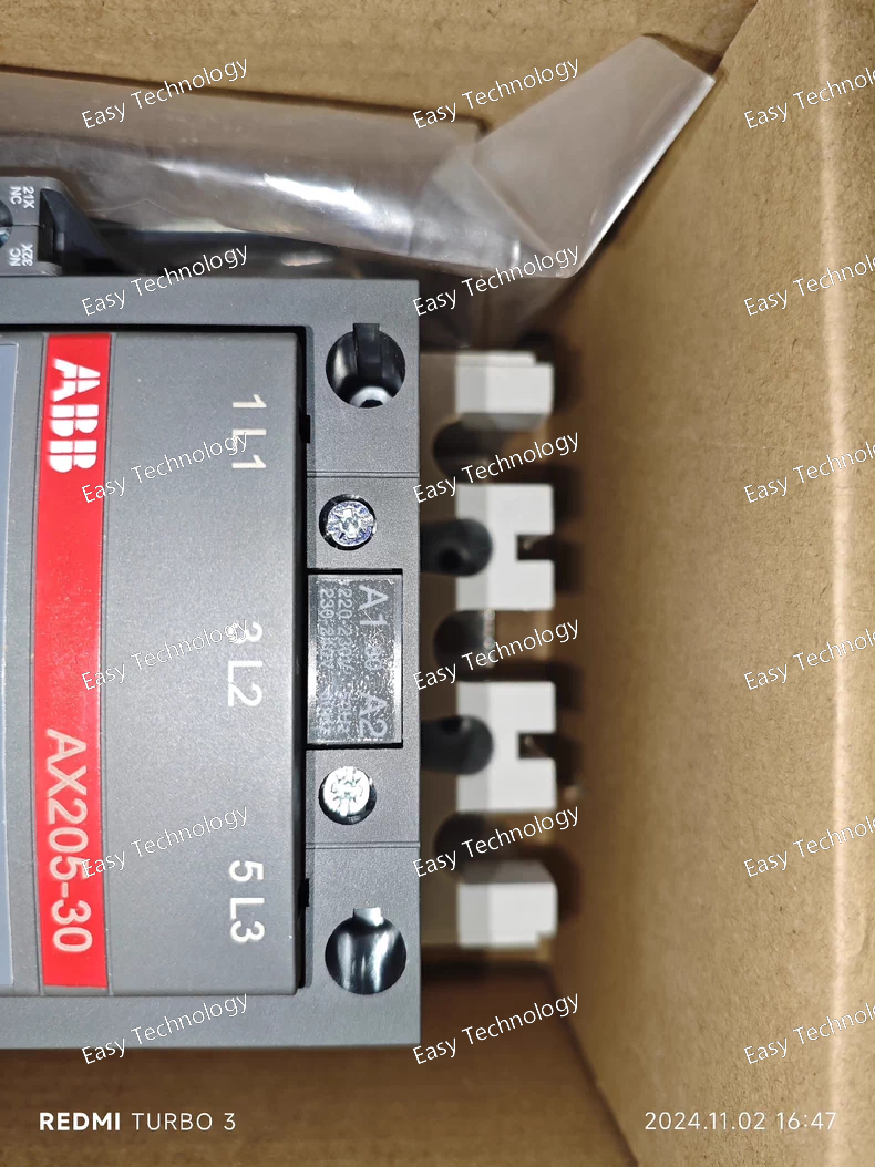
Technical Parameters Parameter / Feature Specification / Detail Model / Type ABB AX205‑30 (AX contactor series) Poles (Main Contacts) 3 poles (3‑phase) — 3 × NO main contacts Auxiliary Contacts 1 × NO + 1 × NC (auxiliary) contacts Rated Operational Current (AC‑3, Ie) 205 A at 400–415 V AC; 185 A at 440 V AC; 170 A at 500 V or 690 V AC depending on configuration Rated Operational Power (AC‑3) Up to ~ 110 kW at 400 V AC; up to ~ 132 kW at 690 V AC, depending on motor/load conditions Rated Insulation Voltage (Ui) 690 V AC (insulation rating, main circuit) Control Coil Voltage (Uc) Options vary (depending on variant) — e.g. 220–230 V AC / 230–240 V AC (50/60 Hz), or other coil voltages depending model code Rated Operational Current (AC‑1, Ie) Up to 275 A at 690 V AC (for non‑inductive / general loads) in some configurations Connection / Terminals Screw / busbar‑type terminals for main contacts; suitable for heavy wiring (e.g. up to 30 mm² conductors) Mechanical / Electrical Durability Designed for many switching cycles, suitable for frequent operation in industrial environments Ambient Operating Temperature Range Wide ambient range, e.g. –40 °C to +70 °C (depending on variant and usage conditions) Protection / Enclosure Terminals rated per standard protection class (e.g. IP20 for terminals) Use Cases / Typical Applications Three‑phase motor control and switching, heavy load switching, industrial machinery control, power distribution systems, general three‑phase AC load management

Technical Parameters Parameter / Feature Specification / Detail Product / Model AX185‑30‑11‑80 (ABB AX series contactor) Poles (Main Contacts) 3‑pole (3 main contacts, NO) Auxiliary Contacts 1 NO + 1 NC (auxiliary contact block) Coil (Control) Voltage 220–230 V AC, 50 Hz / 230–240 V AC, 60 Hz Rated Operational Current (AC‑3) 185 A at 220–240 V AC (for motor switching) Rated Operational Current (AC‑1) Up to 250 A (for resistive/general load) under appropriate conditions Rated Operational Voltage (Main Circuit) Up to 690 V AC (typical for AX series) Rated Operational Power (AC‑3) Example: 90 kW at 400 V AC (varies by voltage and load type) Number of Main Contacts (NO) 3 NO Frequency (Control Circuit) 50 / 60 Hz Coil Type AC‑operated electromagnetic coil Connection / Terminals Screw terminals / bar‑type main connections Use Case / Typical Applications Three‑phase motor start/stop control; power circuits switching; industrial load control; heavy‑duty switching applications Auxiliary Contact Use Control circuits, indicator lamps, interlocks, control logic
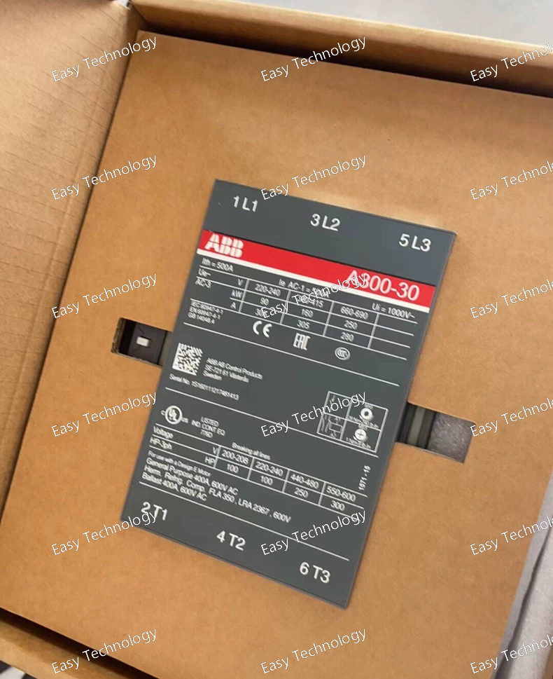
Technical Parameters Parameter / Feature Specification / Detail Model / Type A300‑30‑11‑80, A‑Line series AC contactor Poles (Main Contacts) 3 main poles (3P), normally‑open contacts for power switching Coil Voltage (Control) 230–240 VAC (50 Hz or 60 Hz) Auxiliary Contacts 1 × NO (normally‑open) + 1 × NC (normally‑closed) auxiliary contacts Rated Current (AC‑1) / General Use Up to 400 A (AC‑1) Motor‑switching Rating (AC‑3) 302 A (at specified conditions) for motor control circuits Maximum Motor / Load Capacity Up to 100 HP for single‑phase 208/240 V; higher ratings for 3‑phase at higher voltages (depending on supply) Rated Operational Voltage (Main Circuit) Up to 690 V AC (depending on application) Frame / Contactor Size A300 frame size (compact / industrial contactor) Application Use Motor starting / stopping, motor control, three‑phase power switching, general industrial load control Coil Type Electromagnetic AC coil (magnetic contactor) Termination / Connection Screw‑type terminals for main and auxiliary contacts Typical Use Case Industrial motor control, power distribution, switching of loads in industrial automation or machine control settings
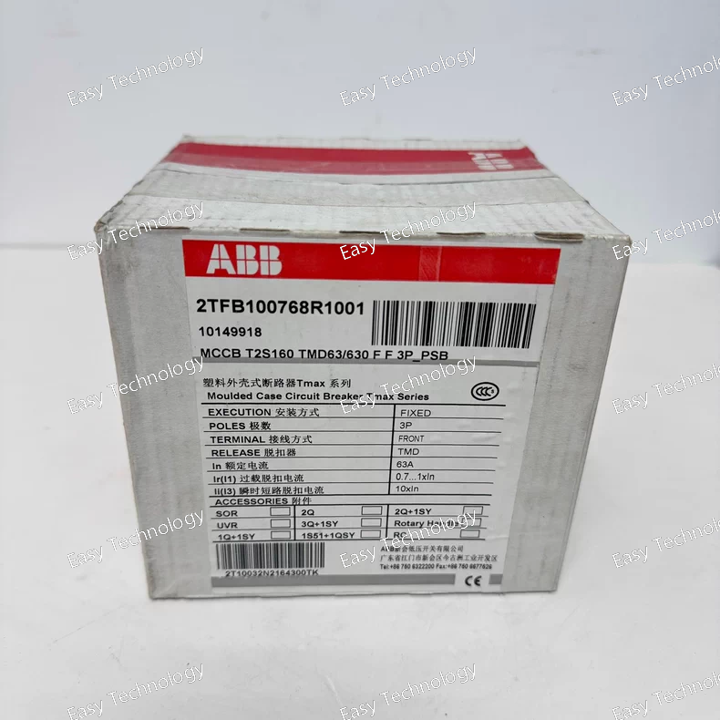
Technical Parameters Parameter / Feature Specification Model / Type T2S160 TMD63/630 FF 3P MCCB Number of Poles 3 poles (3P) Trip Unit Type Thermal‑magnetic (TMD), adjustable instantaneous setting Rated Current (In) 63 A (trip‑unit base setting) Instantaneous Setting Range Adjustable up to 630 A Rated Operational Voltage Up to 690 V AC Rated Insulation Voltage (Ui) 1000 V Rated Impulse Withstand Voltage (Uimp) 8 kV Rated Uninterrupted Current (Iu) 160 A Short‑Circuit Breaking Capacity High breaking capacity (industrial applications) Terminals / Connection Front‑terminal (FF), fixed mounting Rated Frequency 50 / 60 Hz Protection Type Overload and short‑circuit protection via thermal‑magnetic trip unit Typical Applications Industrial/commercial low‑voltage distribution, motor protection, equipment protection, branch‑circuit protection in three‑phase systems
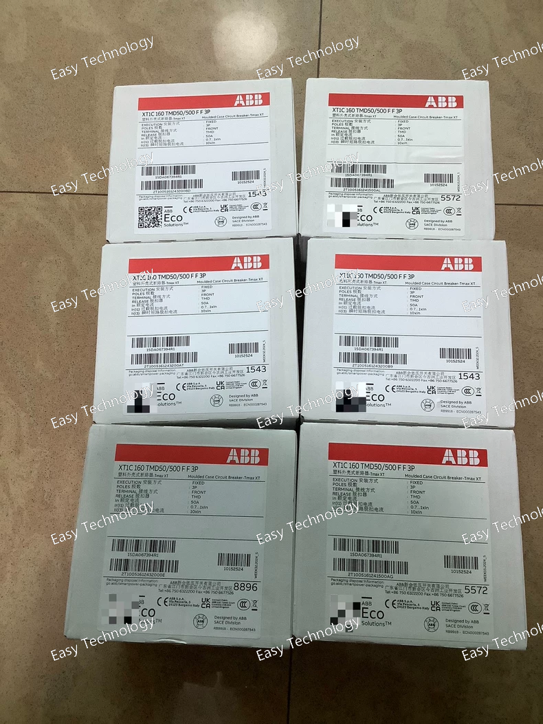
Technical Parameters Parameter / Feature Specification Model / Type XT1C160 TMD50/500 3P FF MCCB Number of Poles 3‑pole (3P) Rated Current 50 A Adjustable Current Range 50 A – 500 A Trip Unit Type Thermomagnetic (TMD), adjustable Rated Operational Voltage Up to 690 V AC Rated Insulation Voltage (Ui) 1000 V Rated Impulse Withstand Voltage (Uimp) 8 kV Short‑Circuit Breaking Capacity High breaking capacity suitable for industrial applications Connection / Terminals Front terminals (FF), fixed mounting Current Type AC / DC compatible Typical Applications Industrial power distribution, motor protection, machinery protection, branch‑circuit protection, general three‑phase load protection
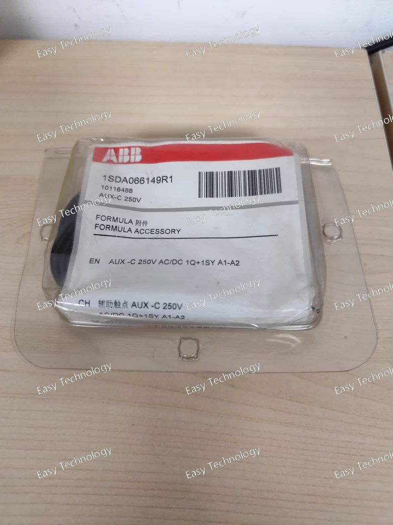
Technical Parameters Parameter / Feature Specification / Detail Product / Type Auxiliary contact module — AUX‑C 1Q+1SY (1SDA066149R1) Function Provides 1 change‑over (CO) contact for breaker ON/OFF status + 1 change‑over contact for trip/fault indication Contact Type SPDT (single‑pole double‑throw) — 2 change‑over contacts total Rated Control / Signal Voltage Up to 250 V AC or DC Suitable Breaker Poles 3‑pole (3P) or 4‑pole (4P) breakers Mounting / Integration Designed as accessory for ABB FORMULA / SACE/ DSA MCCB / circuit‑breaker family Net Weight ~ 0.086 kg Compliance / Standards IEC standard auxiliary‑contact accessory for circuit breakers; accessory classification Typical Applications Remote breaker status signalling (ON/OFF), fault/trip signalling, control panels, monitoring circuits, interlock control logic
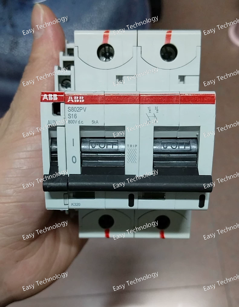
Technical Parameters Parameter / Feature Specification Model / Type S802PV S16 2P MCB Number of Poles 2‑pole (2P) Rated Current 16 A Rated Operational Voltage 240/415 V AC Trip Characteristic Type B (standard for general protection) Breaking Capacity 6 kA at 230/400 V AC Mounting DIN‑rail (35 mm standard) Wiring / Connection Screw terminals Operating Temperature -5 °C to +40 °C Compliance / Standards IEC/EN 60898‑1, CE marked Typical Applications Residential, commercial, light industrial circuits; protection of lighting, socket, and small motor circuits
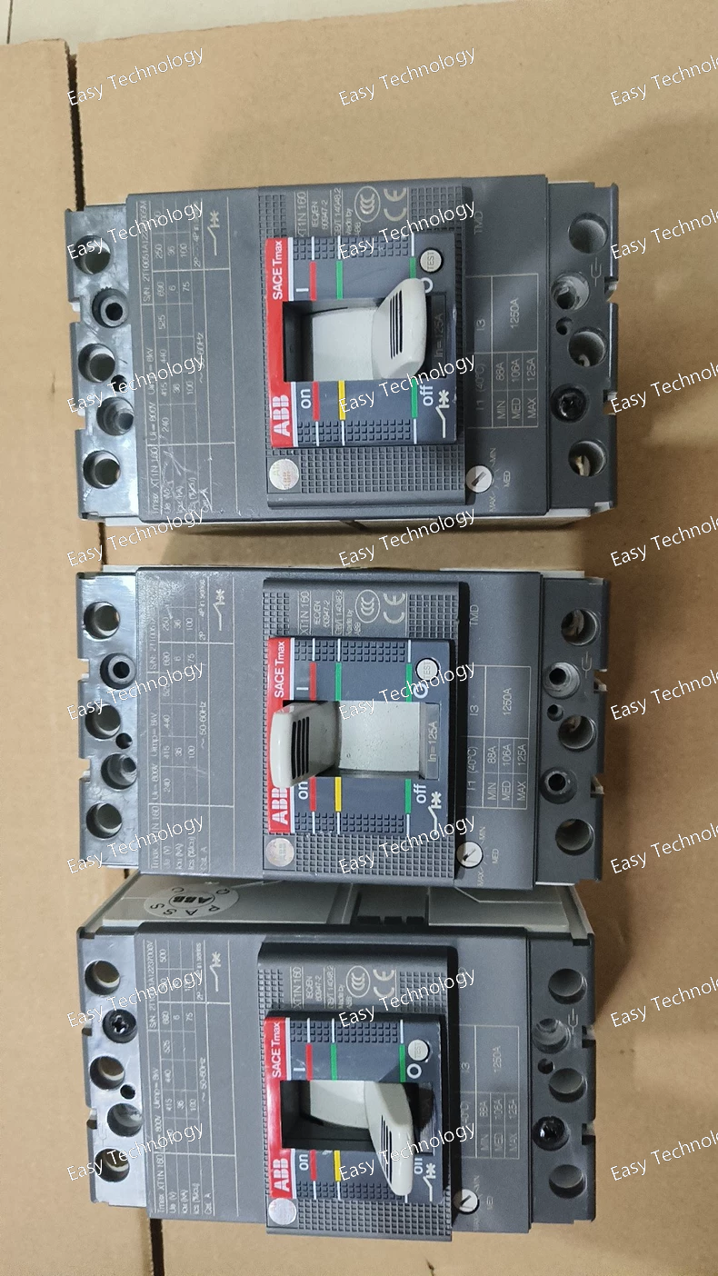
Technical Parameters Parameter / Feature Specification Model / Type XT1N 160 3P MCCB Number of Poles 3‑pole (3P) Rated Current 125 A Trip Unit Type Thermal‑magnetic (TMA) Rated Operational Voltage Up to 690 V AC Rated Insulation Voltage (Ui) 1000 V Rated Impulse Withstand Voltage (Uimp) 8 kV Short‑Circuit Breaking Capacity High breaking capacity suitable for industrial applications Terminals / Connection Front terminals, fixed mounting Current Type AC / DC compatible Typical Applications Industrial power distribution, motor protection, machinery protection, branch‑circuit protection, general three‑phase load protection
Technical Parameters Parameter / Feature Specification Model / Type XT2N160‑50A 3P MCCB Number of Poles 3‑pole (3P) Rated Current 50 A Trip Unit Type Thermal‑magnetic (TMA) Rated Operational Voltage Up to 690 V AC Rated Insulation Voltage (Ui) 1000 V Rated Impulse Withstand Voltage (Uimp) 8 kV Short‑Circuit Breaking Capacity High breaking capacity suitable for industrial applications Terminals / Connection Front terminals (FF), fixed mounting Current Type AC / DC compatible Typical Applications Industrial power distribution, motor protection, machinery protection, branch‑circuit protection, general three‑phase load protection
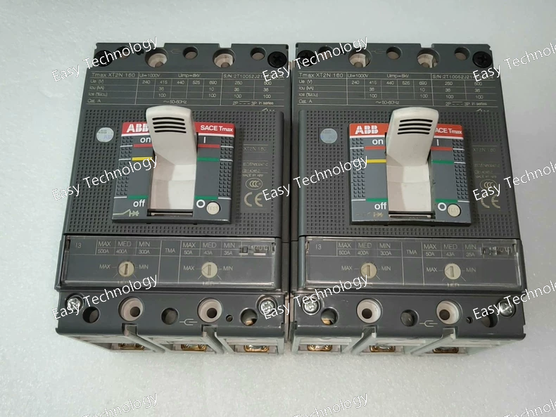
Technical Parameters Parameter / Feature Specification Model / Type XT2N160 3P MCCB Number of Poles 3‑pole (3P) Rated Current 52 A Trip Unit Type Thermal‑magnetic (TMA) Rated Operational Voltage Up to 690 V AC Rated Insulation Voltage (Ui) 1000 V Rated Impulse Withstand Voltage (Uimp) 8 kV Short‑Circuit Breaking Capacity High breaking capacity suitable for industrial use (depends on voltage rating) Connection / Terminals Front terminals (FF), fixed mounting Current Type AC / DC compatible Typical Applications Industrial power distribution, motor protection, machinery protection, branch‑circuit protection, general three‑phase load protection
Technical Parameters Parameter / Feature Specification Model / Type XT2N 160 TMA160‑1600 3P FF MCCB Number of Poles 3‑pole (3P) Trip Unit Type Thermal‑magnetic (TMA), adjustable Rated Operational Current 160 A Adjustable Current Range 160 A – 1600 A Rated Operational Voltage Up to 690 V AC Rated Insulation Voltage (Ui) 1000 V Rated Impulse Withstand Voltage (Uimp) 8 kV Short‑Circuit Breaking Capacity High breaking capacity, suitable for industrial applications (e.g., up to 50 kA–100 kA depending on voltage rating) Connection / Terminals Front terminals (FF), fixed mounting Busbar / Main Circuit Connection Suitable for large busbar connections (size depends on installation) Current Type AC / DC compatible Electrical Durability Thousands of operations at rated load (typical industrial standard) Mechanical Durability Tens of thousands of operations Typical Applications Industrial power distribution, motor protection, machinery protection, branch‑circuit protection, general three‑phase load protection
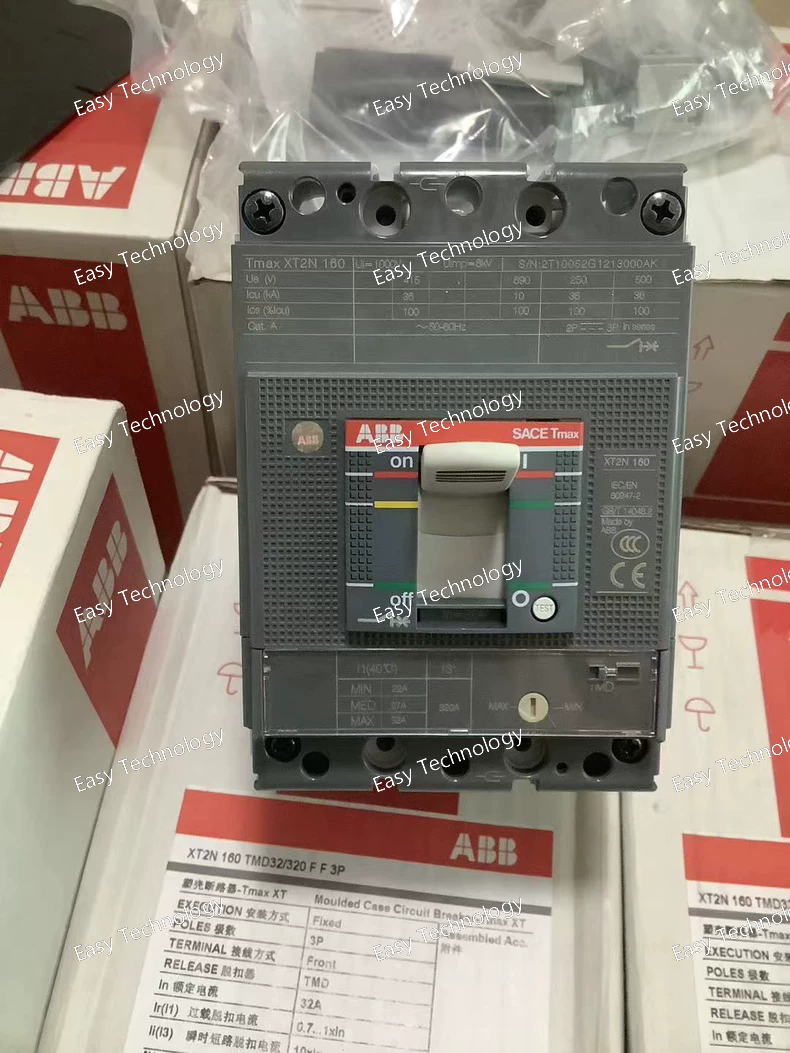
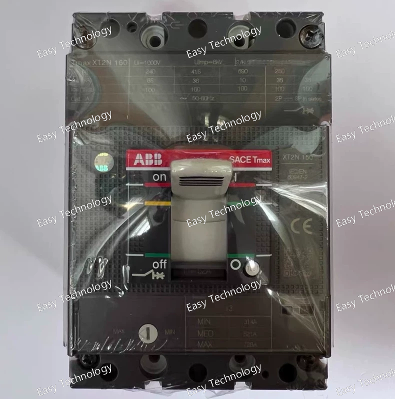
Technical Parameters Parameter / Feature Specification Model / Type XT2N160 TMD32/320 3P FF MCCB Number of Poles 3‑pole (3P) Trip Unit Type Thermomagnetic (TMD), adjustable Adjustable Current Range 32 A to 320 A Rated Operational Current 160 A Rated Operational Voltage Up to 690 V AC / 500 V DC Rated Insulation Voltage (Ui) 1000 V Rated Impulse Withstand Voltage (Uimp) 8 kV Short‑Circuit Breaking Capacity 36 kA at 380‑415 V AC; 30 kA at 500 V AC; 10 kA at 690 V AC Connection Capacity Busbar 32.5–100 mm² Current Type AC / DC compatible Electrical Durability 8,000 operations at rated load Mechanical Durability 25,000 operations Power Loss (per pole) ~2.57 W Terminals / Connection Front terminals (FF), fixed mounting Typical Applications Industrial power distribution, motor protection, equipment protection, branch‑circuit protection in AC/DC systems, general three‑phase load protection
 TEL: Grace +86 13600179521
  Mail: info@hongkongeasy.com jilineasyyi@outlook.com
 Q Q:615739355
 ADDRESS:Unit 12, 20th Floor, Good View Commercial Centre, 2-16 Garden Street, Mong Kok, Hong Kong
 whats app


