
Industrial Controller
All product are in stock,guaranteed delivery within 3-7 days.


PRODUCT
PICTURE
BRAND
DESCRIBE
STOCK
DOWNLOAD
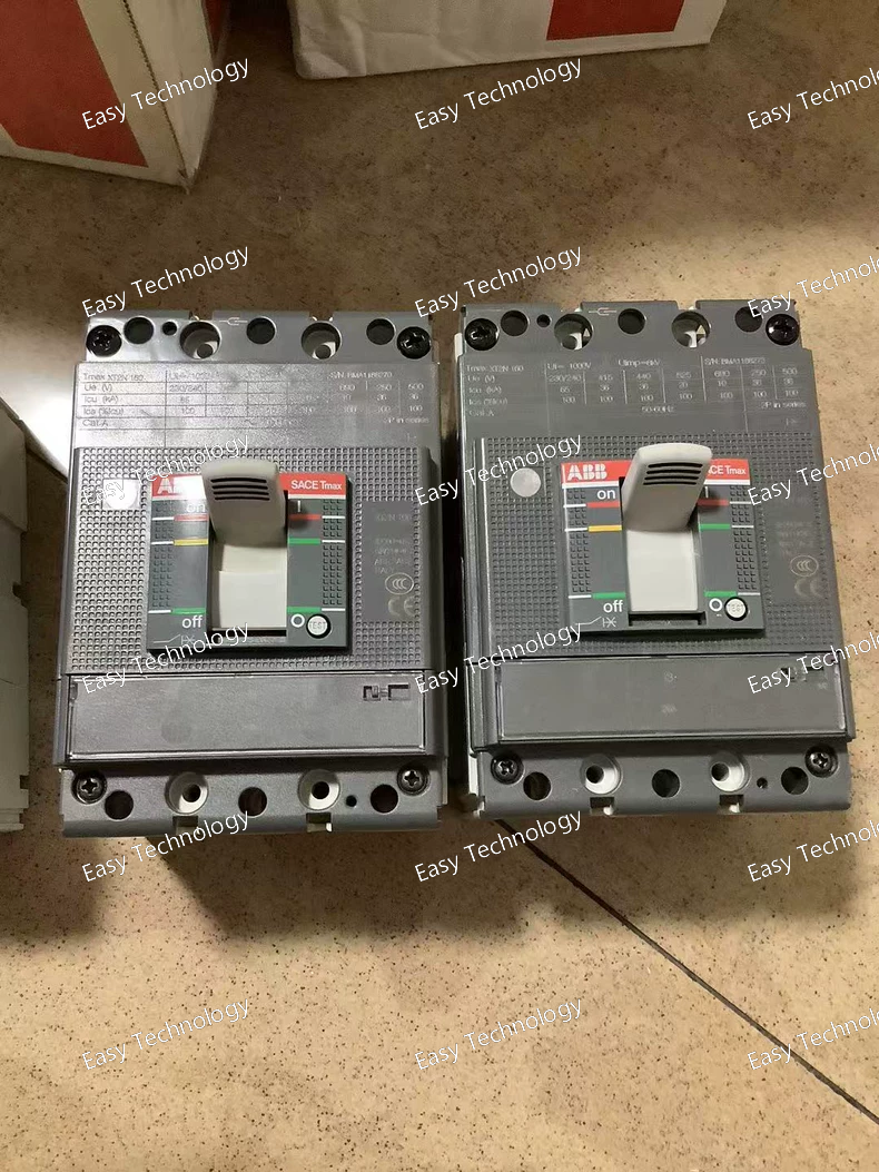
Technical Specifications Parameter Specification Part Number / Model 1SDA067045R1 Product Type Molded Case Circuit Breaker (MCCB) Series / Family Tmax XT2N Trip Unit / Release Magnetic (MF) Number of Poles 3 (3P) Rated Frame Current (Iu) 160 A Magnetic Trip Setting (Ii) 28 A Rated Operational Voltage (Ue) 690 V AC / 500 V DC Rated Insulation Voltage (Ui) 1000 V Rated Impulse Withstand Voltage (Uimp) 8 kV Rated Short‑Circuit Breaking Capacity (Icu) 65 kA @ 220–240 V AC; 36 kA @ 380–440 V AC; 10 kA @ 690 V AC Rated Service Breaking Capacity (Ics) Same as Icu Terminal Type Front bolt terminals Terminal Screw Torque ~6 N·m Mounting Fixed installation Standards Compliance IEC 60947‑2 Mechanical Durability ~25,000 operations Electrical Endurance ~8,000 operations
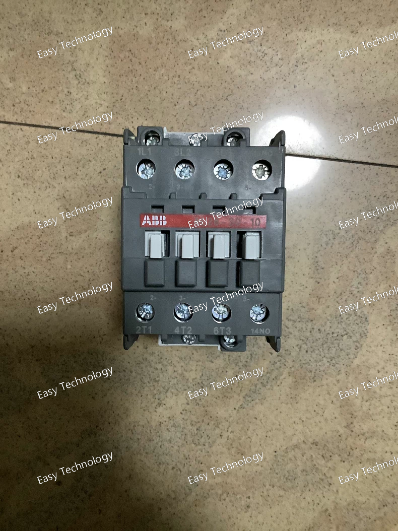
Technical Specifications Parameter Specification Product / Model ABB A26‑30‑10 380‑400V AC Contactor Type Three‑pole AC power contactor Series / Family ABB A26 series contactors (block type) Number of Main Contacts 3 Normally Open (3 NO) Auxiliary Contacts 1 Normally Open (1 NO) built‑in Control Coil Voltage (Uc) 380–400 V AC 50 Hz / 400–415 V AC 60 Hz Rated Operational Voltage – Main Circuit Up to 690 V AC Conventional Free‑Air Thermal Current (Ith) ~45 A (at 40 °C free air) Rated Operational Current (AC‑1) ~45 A (690 V AC, 40 °C) Rated Operational Current (AC‑3) ~26 A at 380–440 V AC (typical) Rated Operational Power (AC‑3) ~11 kW at 380–400 V AC Rated Insulation Voltage (Ui) 1000 V (IEC) Rated Impulse Withstand Voltage (Uimp) 8 kV Rated Breaking/Making Capacity (AC‑3) 8× / 10× Ie Short‑Time Withstand Current (Icw) 210–400 A depending on duration Switching Frequency (Electrical) AC‑1: 600 cycles/h; AC‑3: 1200 cycles/h Mechanical Durability ~10,000,000 operations Terminal Type Screw terminals Mounting Panel / DIN‑rail compatible Degree of Protection IP20 Coil Consumption ~3–12 VA holding, with pull‑in values per IEC Application Motor control, power switching, lighting & general loads
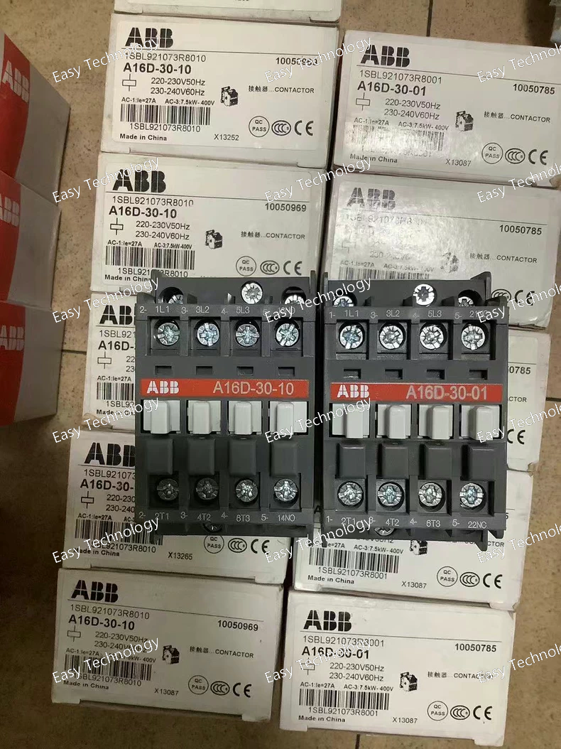
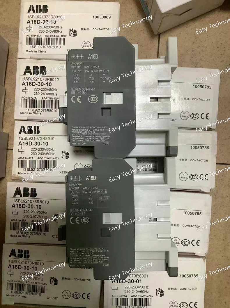
Technical Specifications Parameter Specification Part / Model ABB A12‑30‑01 220‑230 V AC Contactor (e.g., 1SBL161001R8001) Product Type Three‑pole AC power contactor Number of Main Contacts 3 Normally Open (3 NO) Auxiliary Contacts 1 (typically NC or configurable) Control Coil Voltage (Uc) 220‑230 V AC (50 Hz) / 230‑240 V AC (60 Hz) Rated Operational Voltage – Main Circuit Up to 690 V AC Conventional Free‑Air Thermal Current (Ith) ~28 A (IEC 60947‑4‑1) Rated Operational Current AC‑1 (Ie) ~27 A @ 690 V (40 °C) Rated Operational Current AC‑3 (Ie) ~12 A @ 220‑240 V AC Rated Operational Power AC‑3 (Pe) ~3 kW @ 220–240 V AC; ~5.5 kW @ 380–415 V AC Rated Operational Current AC‑15 (Ie) ~4 A @ 220‑240 V AC Rated Insulation Voltage (Ui) 1000 V IEC Rated Impulse Withstand Voltage (Uimp) 8 kV Rated Making / Breaking Capacity AC‑3: 10× / 8× Ie Switching Frequency AC‑1: ~600 cycles/hr; AC‑3: ~1200 cycles/hr Mechanical Durability ~10 million operations Coil Consumption ~8 VA holding; ~70–74 VA pull‑in Connection / Terminals Screw terminals for main and control wiring Mounting DIN‑rail / panel mount capable Standards Compliance IEC 60947‑4‑1, IEC 60947‑5‑1 Ambient Operating Temperature Range Typically −40 °C to +55 °C Typical Weight ~0.34 kg Typical Dimensions (approx.) Width ~44 mm, Height ~74 mm, Depth ~74 mm
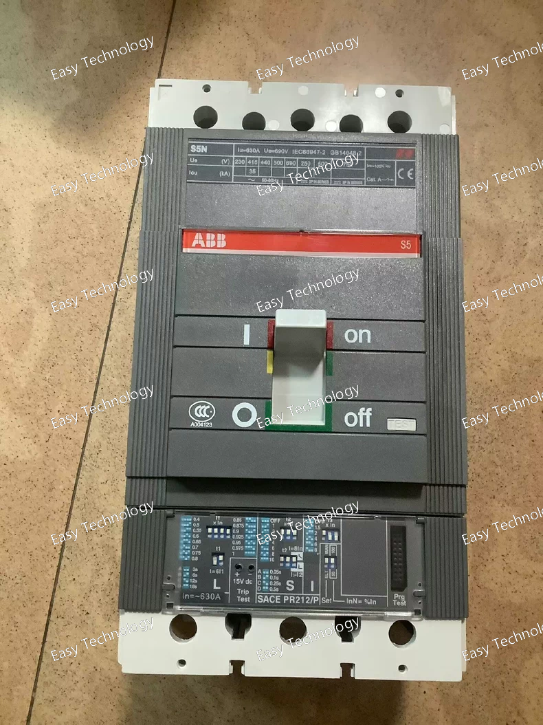
Technical Specifications Parameter Specification Part Number / Model ABB 1SDA038676R1 Product Type Molded Case Circuit Breaker (MCCB) Series / Family SACE Isomax S5 Trip Unit Type PR212‑P electronic release with LSI (Long‑Time, Short‑Time, Instantaneous) Number of Poles 3 poles (3P) Rated Current (In) 630 A Protection Functions Overload (L), Short‑Time (S), Instantaneous (I) Rated Operational Voltage (Ue) Up to 690 V AC typical Frame / Housing Fixed MCCB with front terminal connections IEC Utilization Category IEC 60947‑2 compliant Settings / Adjustments Adjustable trip parameters via PR212‑P release Auxiliary / Control Electronic trip unit for coordination and protection Mounting Panel / switchgear fixed installation Application Overload and fault protection in power distribution and industrial circuits Typical Accessories Auxiliary contacts, shunt trip, alarm contact modules (optional)
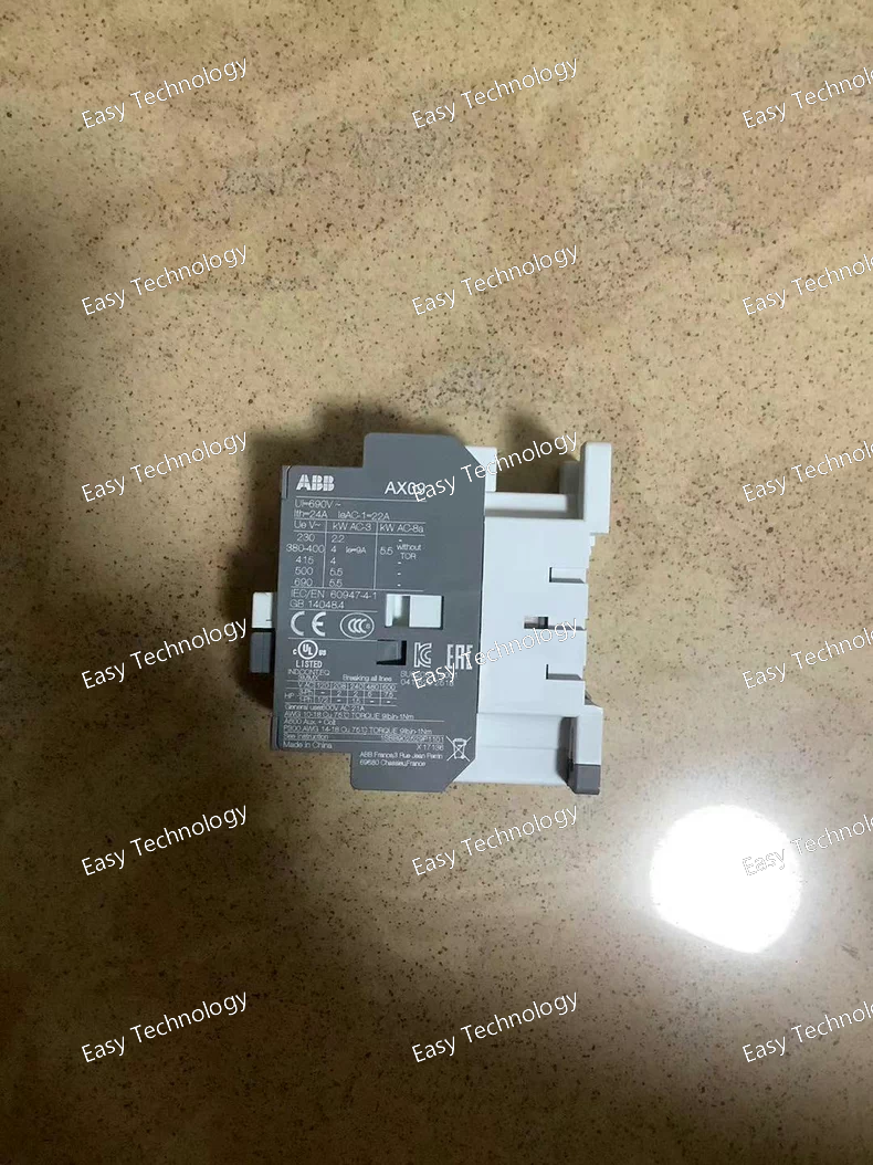
Technical Specifications Parameter Specification Part Number / Model AX09‑30‑01‑81 / 1SBL901074R8101 Product Type AC Power Contactor Series / Family AX series Control Coil Voltage 24 V AC, 50/60 Hz Number of Poles 3 main poles (3P) Main Contacts 3 Normally Open (NO) Auxiliary Contacts 1 Normally Closed (NC) built‑in Rated Operational Voltage (Main Circuit) Up to 690 V AC Rated Operational Current (AC‑1) ~22 A at 690 V AC Rated Operational Current (AC‑3) ~9 A (typical motor control duty) Rated Operational Power (AC‑3) up to ~4–5.5 kW depending on voltage Rated Insulation Voltage (Ui) 690 V (IEC 60947‑4‑1) Rated Frequency 50 / 60 Hz (main & control circuits) Conventional Free‑Air Thermal Current (Ith) 24 A Maximum Breaking Capacity ~250 A at 440 V AC; ~90 A at 690 V AC Switching Frequency (Electrical) AC‑1: 600 cycles/hour; AC‑3: 1200 cycles/hour Switching Frequency (Mechanical) 3600 cycles/hour Short‑time Withstand Current (Icw) ~100 A for 10 s (cold) Terminal Type Screw terminals Mounting DIN‑rail / panel compatible Operating Temperature Range ~‑40 °C to +70 °C Degree of Protection IP20 Dimensions (approx.) Width ~44 mm × Height ~74 mm × Depth ~74 mm Weight (approx.) ~0.33 kg
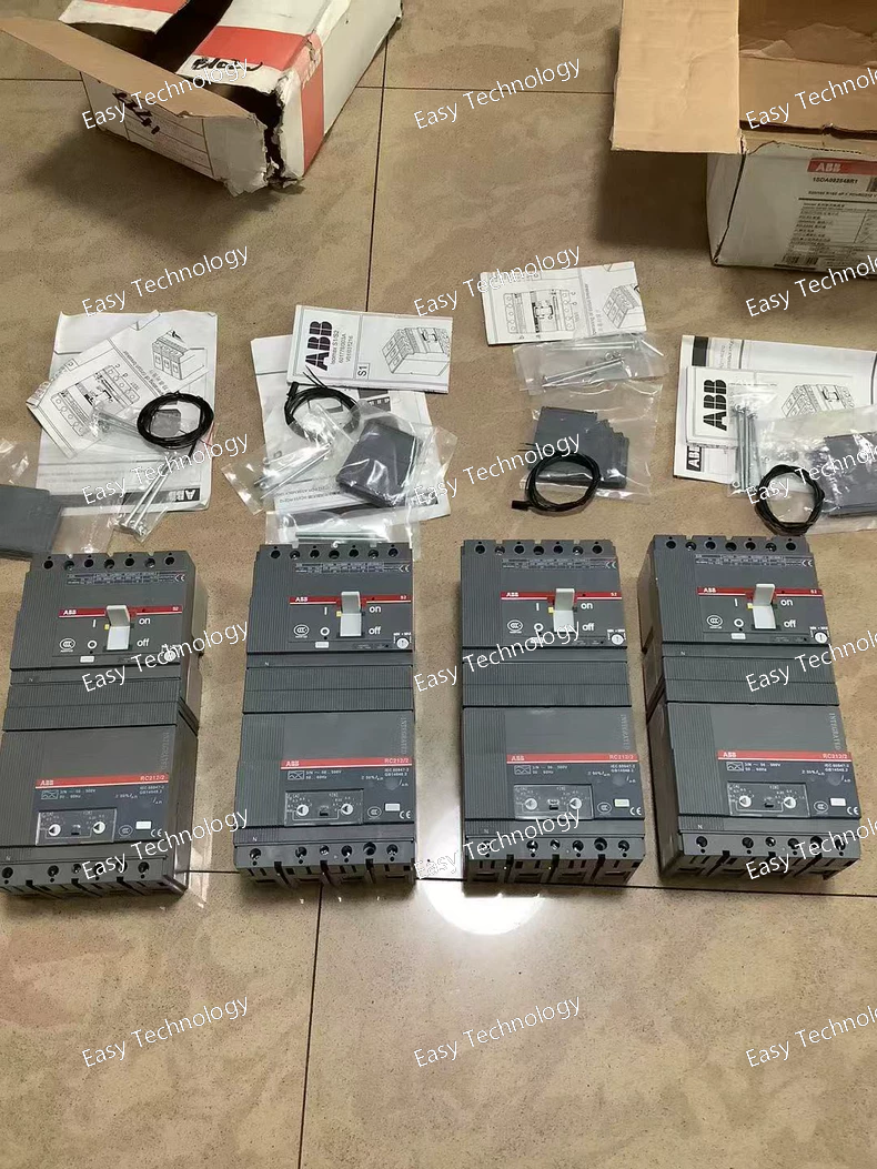
Technical Specifications Part Number / Model 1SDA092548R1 Product Type Molded Case Circuit Breaker (MCCB) Series / Family S2N / ABB Circuit Breaker Number of Poles 4 Poles (4P) Rated Current (In) 160 A Model Designation S2N160 R160 4P FFC+RC212V Trip Mechanism Thermal‑magnetic protection Frame / Housing Plastic casing for compact installation Rated Operational Voltage (Ue) Up to typical low‑voltage AC systems (e.g., 230/400 V AC) Application Overload and short‑circuit protection in distribution boards and panels Accessories May include auxiliary contacts or releases such as RC212V Mounting Panel / DIN‑rail compatible depending on enclosure Standards Compliance Designed to meet IEC and relevant low‑voltage circuit breaker standards
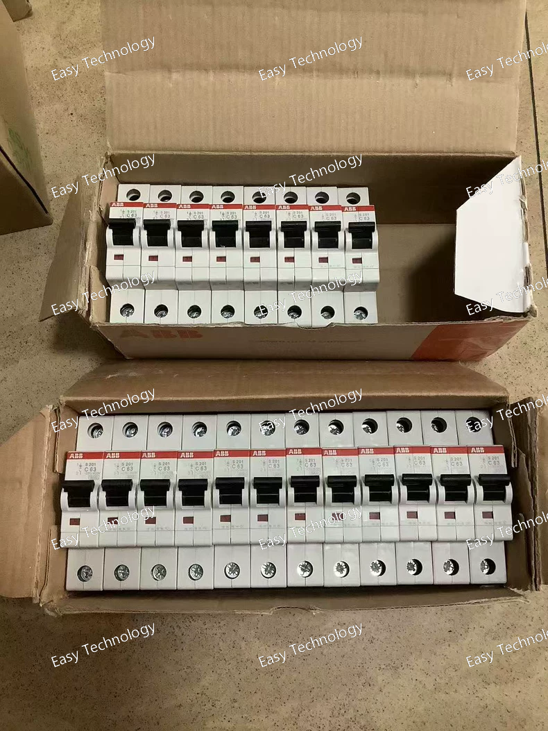
Technical Specifications Parameter Specification Part Number / Model 2CDS251001R0634 Product Name Miniature Circuit Breaker — S201‑C63 Series / Family ABB System pro M compact (S200) Configuration Single pole (1P) Tripping Characteristic Type C (general purpose) Rated Current (Iₙ) 63 A Rated Operational Voltage 230/400 V AC (IEC 60898‑1); 230 V AC (IEC 60947‑2) Rated Insulation Voltage (Uᵢ) 440 V Rated Impulse Withstand Voltage (Uᵢₘₚ) 4 kV (air altitude); higher values at sea level Operational Voltage Range 12–253 V AC; 12–72 V DC Rated Short‑Circuit Capacity (Icn) 6 kA (AC) Rated Ultimate Short‑Circuit Breaking Capacity (Icu) 10 kA at 230/400 V AC Rated Service Short‑Circuit Breaking Capacity (Ics) 7.5 kA (230 V AC) Energy Limitation Class Class 3 Overvoltage Category III Pollution Degree 3 Power Loss ~4.8 W per pole Frequency 50/60 Hz Degree of Protection IP20 Operating Ambient Temperature −25 °C to +55 °C Mounting DIN‑rail (TH35) Terminal Type Screw terminals with lifted cylindrical design Endurance Electrical ~10,000 cycles; Mechanical ~20,000 cycles Contact Position Indication Red (ON) / Green (OFF) Standards Compliance IEC/EN 60898‑1; IEC/EN 60947‑2; UL 1077 Accessories Bottom‑fitting auxiliary contacts possible
Technical Specifications Parameter Specification Part / Model AL26‑30‑10 24 V DC Contactor Product Type Power Contactor Series / Family ABB AL Series Coil Voltage (Rated Control Voltage) 24 V DC Main Contacts 3 normally open (3 NO) Auxiliary Contacts 1 normally open (1 NO) Rated Operational Voltage – Main Circuit up to 690 V AC Rated Operational Current AC‑1 (Ie) 45 A (690 V, 40 °C) / 40 A (55 °C) Rated Operational Current AC‑3 (Ie) ~26 A (220–440 V AC) / ~13 A (690 V AC) Rated Operational Power AC‑3 (Pe) up to 15 kW (440–500 V AC) / ~11 kW (380–690 V AC) Rated Making Capacity AC‑3 10 × Ie Rated Breaking Capacity AC‑3 8 × Ie Rated Operational Current DC‑13 (Ie) 6 A / 144 A (24 V DC) Conventional Free‑Air Thermal Current (Ith) 45 A Max Mechanical Switching Frequency ~3600 cycles/hour Max Electrical Switching Frequency AC‑1: ~600 cycles/hour; AC‑3: ~1200 cycles/hour Operate / Release Times Close: ~55 – 110 ms; Open: ~12 – 18 ms Terminal Type Screw terminals Rated Insulation Voltage (Ui) ~1000 V (IEC 60947‑4‑1) Rated Frequency (Main Circuit) 25 – 400 Hz Ambient Operating Temperature –40 °C to +55 °C Mechanical Durability High cycle life per IEC standards Mounting DIN‑rail / panel mounting capable Standards Compliance IEC/EN 60947‑4‑1, IEC/EN 60947‑5‑1 Weight (approx.) ~0.75 kg Dimensions (approx.) Width ~54 mm × Height ~90 mm × Depth ~110 mm
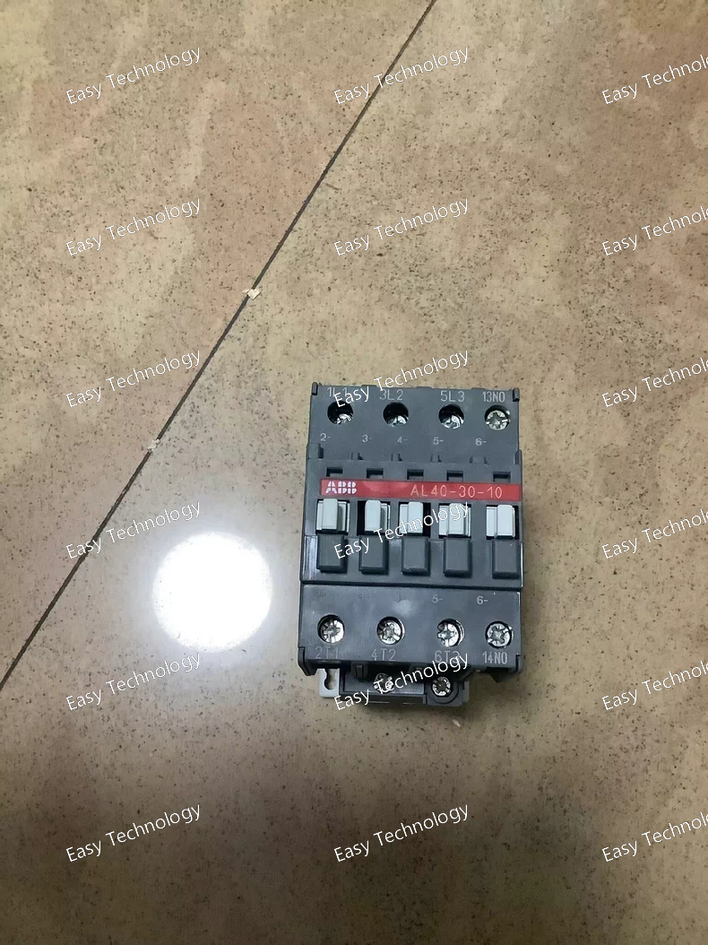
Technical Specifications Parameter Specification Part Number / Model 1SBL323001R8810 ABB Type / Code AL40‑30‑10 DC Contactor Coil Voltage 220 V DC Number of Poles 3 main poles (3 NO) Auxiliary Contacts 1 normally‑open (1 NO) Rated Operational Current – AC‑1 (Ie) 60 A at 690 V AC free‑air thermal current Rated Operational Current – AC‑3 (Ie) 37 A at 415 V AC Rated Operational Power (AC‑3) 18.5 kW at 400 V AC Control Coil Consumption ~3.5 W (low‑consumption DC coil) Rated Insulation Voltage (Ui) 1000 V Rated Short‑time Withstand Current (Icw) 400 A for 10 s Terminal Type Screw terminals Mounting Panel / DIN rail capable (block contactor design) Rated Frequency (Control) DC control Rated Frequency (Main) 25‑400 Hz Ambient Air Temperature –25 °C to +55 °C (operating) Product Class Block contactor per IEC 60947‑4‑1 Weight (approx.) 0.85 kg Product Range ABB AL Contactors
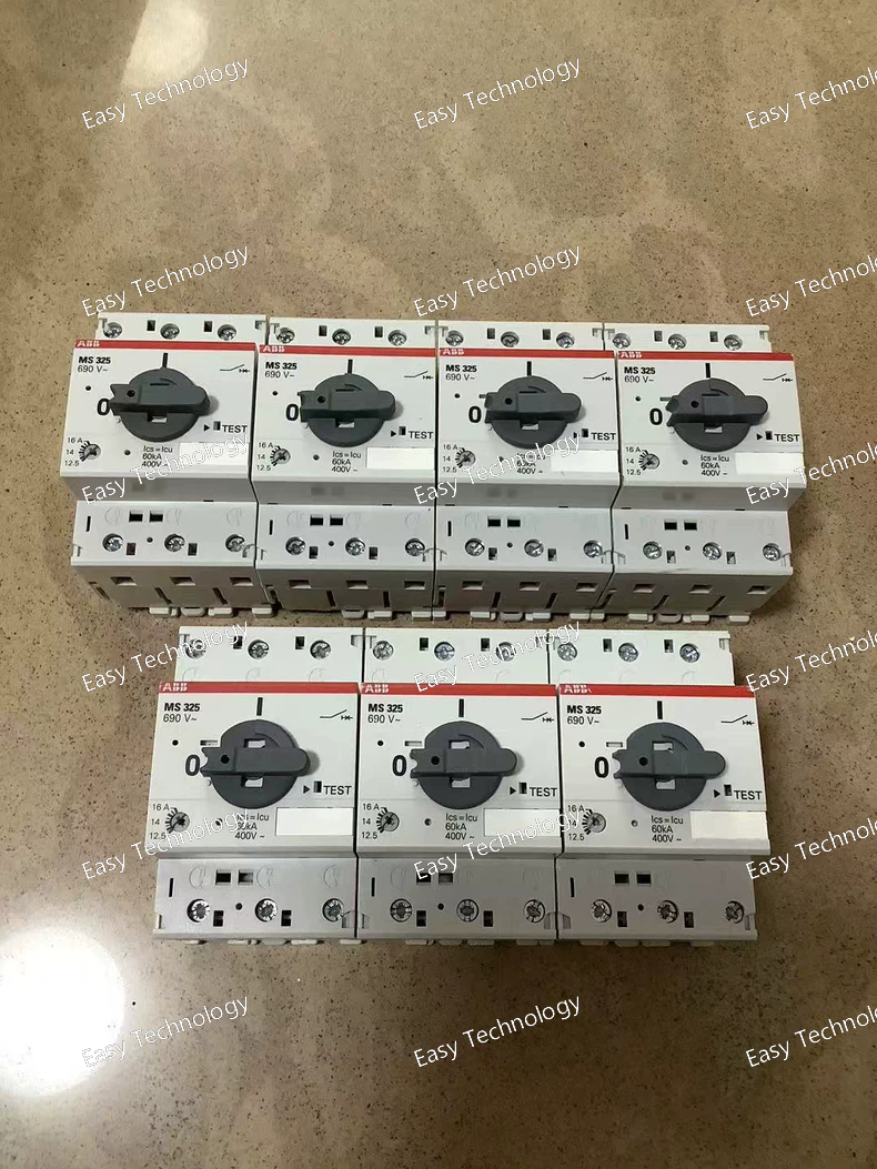
Technical Specifications Parameter Specification Product Manual Motor Starter Model / Part Number MS325‑16 Rated Operational Current (Ie) 16 A Setting Range (Overload Protection) 12.5 – 16 A Number of Poles 3 poles Rated Operational Voltage (Ue) up to 690 V AC and 440 V DC Rated Service Short‑Circuit Breaking Capacity (Ics) 100 kA at 230 V AC, 60 kA at 400 V AC, 40 kA at 440 V AC, 25 kA at 500 V AC, 4 kA at 690 V AC Rated Ultimate Short‑Circuit Breaking Capacity (Icu) Same as Ics Rated Instantaneous Short‑Circuit Current Setting (Ii) 240 A Rated Operational Power AC‑3 ~7.5 kW (400 V AC) Trip Class Class 10A Control / Handle Rotary ON/OFF handle with clear indication Functions Manual switching, overload protection, short‑circuit protection Disconnect Function Built‑in Temperature Compensation Yes Trip‑Free Mechanism Yes Poles in Series for Single‑Phase 3 poles can be used in series Auxiliary / Accessory Options Auxiliary contacts, signalling contacts, undervoltage release, shunt trip (optional) Enclosure Protection IP20 Operating Temperature Range –25 °C to +50 °C (typical) Mechanical Durability High cycle life (thousands of operations) Dimension (approx.) Width: 54 mm, Height: 87.5 mm, Depth: 75.5 mm Standards Compliance IEC/EN 60947‑4‑1 / IEC/EN 60947‑1 series
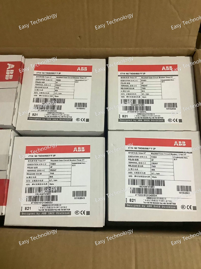
Technical Specification Parameter Specification Part / Model ABB XT1N160 TMD80‑800 FF 3P Product Type Molded Case Circuit Breaker (MCCB) Series / Family ABB Tmax XT Number of Poles 3‑pole (3P) Trip Unit Type Thermal‑magnetic (TMD), adjustable (80–800 A) Rated Current (I<sub>n</sub>) 80 A Rated Uninterrupted Current (I<sub>u</sub>) 160 A Operational Voltage (U<sub>e</sub>) 690 V AC / 500 V DC Rated Insulation Voltage (U<sub>i</sub>) 800 V Rated Impulse Withstand Voltage (U<sub>imp</sub>) 8 kV Rated Ultimate Short‑Circuit Breaking Capacity (I<sub>cu</sub>) up to 65 kA (at lower AC voltages) Rated Service Short‑Circuit Breaking Capacity (I<sub>cs</sub>) up to 50 kA (at lower AC voltages) Rated Instantaneous Short‑Circuit Setting (I<sub>i</sub>) 800 A Frequency 50/60 Hz Mounting Type Fixed installation (front terminals) Terminal Connection Front bolt connections Mechanical Durability ~25,000 operations Electrical Durability ~8,000 operations Power Loss per Pole ~4.8 W Standards Compliance IEC 60947‑2 Typical Use Power distribution protection in industrial/commercial installations
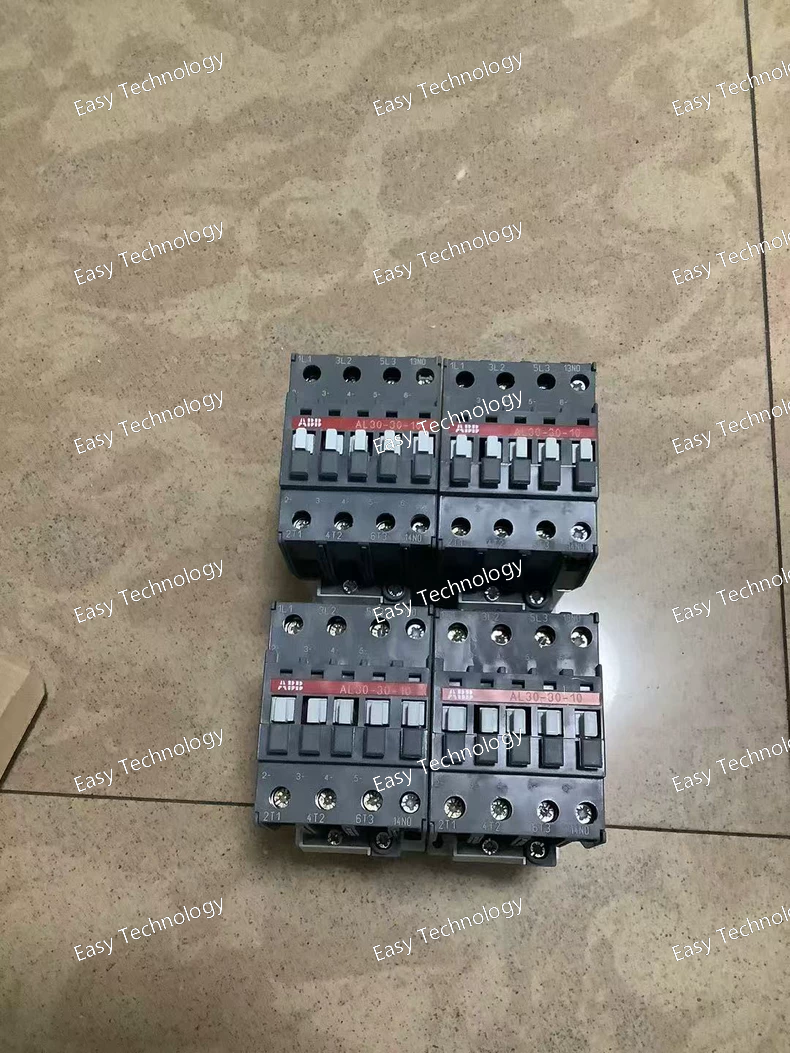
Technical Specifications Parameter Specification Part Number / Model 1SBL283001R8110 Product AL30‑30‑10 Power Contactor Contact Configuration 3 main poles + 1 auxiliary contact (1 NO) Rated Control / Coil Voltage 24 V DC Rated Operational Voltage (Main Circuit) up to 690 V AC Rated Operational Current AC‑3 (Ie) ~30–33 A (at 380–415 V AC) Rated Operational Current AC‑1 (Ie) ~55 A (at 690 V AC) Rated Operational Power AC‑3 (Pe) up to ~15 kW (at 380–415 V AC) Rated Breaking Capacity AC‑3 8 × Ie Auxiliary Contacts 1 Normally Open (1 NO) Max Switching Frequency up to ~1200 cycles/hour (AC‑3) Coil Consumption Low consumption DC coil (~3.5 W) Terminal Type Screw terminals Mounting DIN‑rail / Panel mount compatible Operating Frequency 50–60 Hz Rated Insulation Voltage (Ui) 1000 V (IEC) Rated Impulse Withstand Voltage (Uimp) 8 kV Ambient Temperature (Operating) –40 °C to +55 °C Degree of Protection IP20 Mechanical Life High mechanical durability typical for IEC 60947‑4‑1 block contactors Standards Compliance Designed to IEC 60947‑4‑1 and related industrial standards
 TEL: Grace +86 13600179521
  Mail: info@hongkongeasy.com jilineasyyi@outlook.com
 Q Q:615739355
 ADDRESS:Unit 12, 20th Floor, Good View Commercial Centre, 2-16 Garden Street, Mong Kok, Hong Kong
 whats app


