
Industrial Controller
All product are in stock,guaranteed delivery within 3-7 days.


PRODUCT
PICTURE
BRAND
DESCRIBE
STOCK
DOWNLOAD
Key Specifications (English) General Manufacturer: ABB Model / Part Number: AX150‑30‑11‑85 / 1SFL991074R8511 Product Type: 3‑Phase AC Power Contactor Series: AX Series Main Circuit Number of Main Contacts (NO): 3 Number of Main Contacts (NC): 0 Auxiliary Contacts: 1 Normally Open (NO) + 1 Normally Closed (NC) Rated Operational Voltage (Main Circuit): Up to 1000 V AC (IEC) Rated Frequency: 50 Hz / 60 Hz Conventional Free‑air Thermal Current (Ith): ~190 A @ 40 °C Rated Operational Current (AC‑1, Ie): • ~190 A @ 690 V AC (40 °C) • ~145 A @ 690 V AC (55 °C) • ~130 A @ 690 V AC (70 °C) Rated Operational Current (AC‑3, Ie): • ~150 A @ 380/400 V AC (55 °C) • ~100 A @ 440–500 V AC (55 °C) • ~82 A @ 690 V AC (55 °C) Rated Operational Power (AC‑3): • ~75 kW @ 380/400 V AC • ~59 kW @ 440–500 V AC • ~75 kW @ 690 V AC Rated Breaking Capacity (AC‑3): 8 × Ie Rated Making Capacity (AC‑3): 10 × Ie Control / Coil Rated Control Circuit Voltage (Uc): Typically 380 … 400 V AC @ 50 Hz (also suitable for 400 … 415 V AC @ 60 Hz) — designed to match typical industrial supply voltages around 380 V AC. Performance & Durability Rated Insulation Voltage (Ui): ~690 V (IEC) Rated Impulse Withstand Voltage (Uimp): ~8 kV Maximum Electrical Switching Frequency: ~300 cycles/hour Mechanical Durability: ~10 million operations Maximum Mechanical Switching Frequency: ~3600 cycles/hour Short‑time Withstand Current (Icw): • ~1320 A @ 1 s • ~800 A @ 10 s • ~350 A @ 1 min • ~160 A @ 15 min Mechanical & Environmental Main Circuit Terminals: Heavy‑duty bar connections Ambient Operating Temperature: ~‑40 °C to +70 °C (depending on installation conditions) Protection Class: Auxiliary terminals commonly IP40 Typical Uses 3‑phase motor control and switching Industrial power distribution Load isolation and control in automation systems Control panels and machinery requiring high current switching
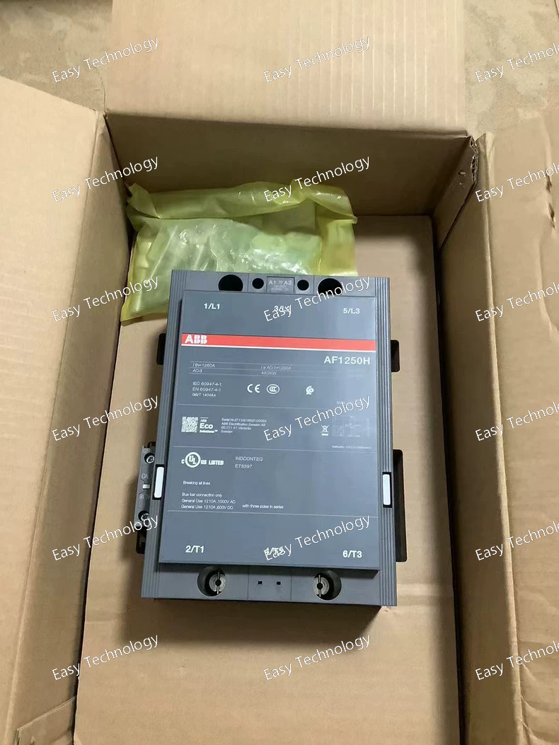
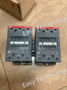
Key Specifications General / Electrical Model / Part Number: AF1250‑30‑11 / 1SFL647088R7011 Product Type: Industrial 3‑phase power contactor Number of Poles: 3 main poles (3NO) Auxiliary Contacts: Typically includes 1 normally open (NO) and 1 normally closed (NC) auxiliary contact Rated Operational Voltage (Main Circuit): Up to 1000 V AC (IEC) and 600 V AC (UL) Rated Control Circuit Voltage: 100–250 V AC/DC wide range Rated Operational Current (AC‑1): ~1260 A at 40 °C for AC main circuit Break / Make Performance: Designed for heavy power switching duties Performance Accepts a wide control voltage range (100–250 V AC or DC) for flexible control circuits Built‑in surge protection on coils for improved reliability under fluctuating supply conditions Suitable for industrial applications requiring robust switching of high currents and voltages Mechanical & Installation Connection Type: Heavy duty screw or bus bar connections for main circuit Block Format: Compact block design to allow extension with accessories or auxiliary blocks Mounting: Panel or enclosure mounting depending on system design Typical Uses Power distribution switching Motor control and bypass circuits Isolation of large loads in industrial control systems Switching circuits in automation and heavy industry
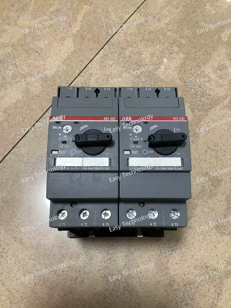
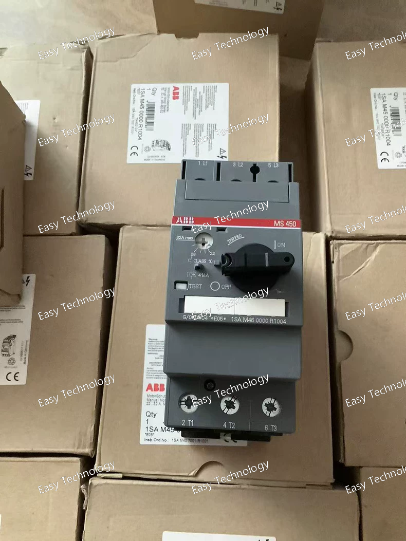
Key Specifications Electrical Ratings Model: MS132‑6.3 Function: Manual motor starter / Motor protection circuit breaker Adjustable Current Range: 4.0 – 6.3 A (thermal overload setting) Rated Operational Current (Ie): 6.3 A Rated Insulation Voltage (Ui): 690 V AC / 250 V DC Rated Operational Voltage (Ue): Up to 690 V AC (50/60 Hz) Rated Operational Power (AC‑3): ~2.2 kW @ 400 V AC (three‑phase) Breaking Capacity (Ics): 100 kA Trip Class: Class 10 (thermal trip characteristic) Protection & Functionality Overload Protection: Adjustable thermal overload to protect motors from overcurrent. Short‑Circuit Protection: Built‑in automatic short‑circuit interruption; no external fuse required. Phase Failure Sensitivity: Detects loss of phase to prevent motor damage. Disconnect Feature: Acts as a manual disconnect switch. Mechanical & Installation Poles: 3‑pole (3P) Control Type: Rotary handle with ON/OFF/TRIP indicator Handle Lockable: Yes Mounting: Standard TH35 DIN rail compatible Terminal Connections: Screw terminals Environmental & Physical Protection Rating: IP20 (finger‑safe enclosure) Operating Temperature: −25 °C to +70 °C Storage Temperature: −40 °C to +80 °C Dimensions: ~45 mm width × ~90 mm height × ~86.8 mm depth Mechanical Lifespan: ~100 000 switching cycles Typical Applications Motor control and protection in industrial automation systems Protection of small motors in pumps, fans, conveyors Manual switching and thermal protection combined in motor control panels Applications in three‑phase and single‑phase circuits where motor protection is required
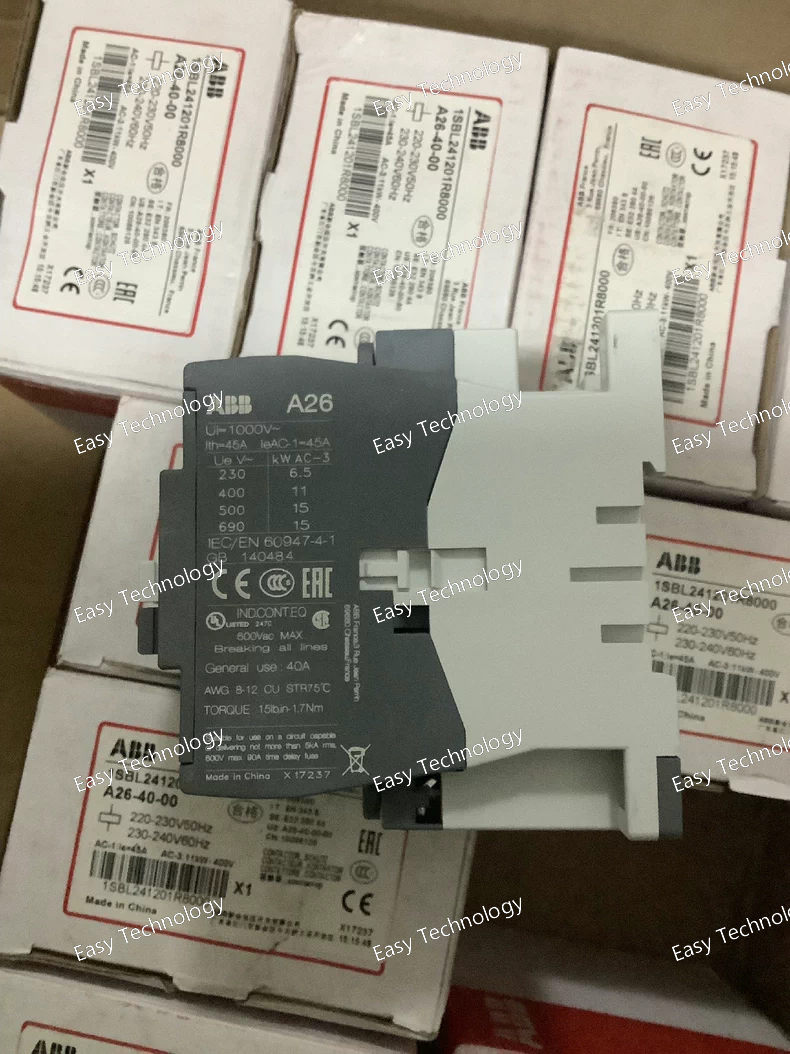
Specifications General Product type: AC Contactor Model: A26‑40‑00 Series: A Contactors Poles: 4 main poles (no auxiliary contacts by default) Control / Coil Rated control circuit voltage (Uc): 220–230 V AC @ 50 Hz; 230–240 V AC @ 60 Hz Coil Power Consumption (typical): ~12 VA holding Main Circuit Rated operational voltage (Ue): Up to 690 V AC Conventional free‑air thermal current (Ith): ~45 A (40 °C) Rated operational current (Ie AC‑3): ~26 A @ 220–240 V AC Rated operational power AC‑3: ~6.5 kW @ 220–240 V Breaking capacity (AC‑3): 8×Ie Making capacity (AC‑3): 10×Ie Performance Max. electrical switching frequency: ~1200 cycles/hour (AC‑3) Max. mechanical switching frequency: ~3600 cycles/hour Mechanical & Environmental Terminal type: Screw terminals Ambient temperature (operating): −40 °C to +70 °C Storage temperature: −60 °C to +80 °C Standards & Insulation Rated insulation voltage (Ui): ~600 V UL/CSA; ~1000 V IEC Dimensions & Weight Approx. Dimensions: ~101 mm × 115 mm × 61 mm Weight (approx.): ~0.61 kg
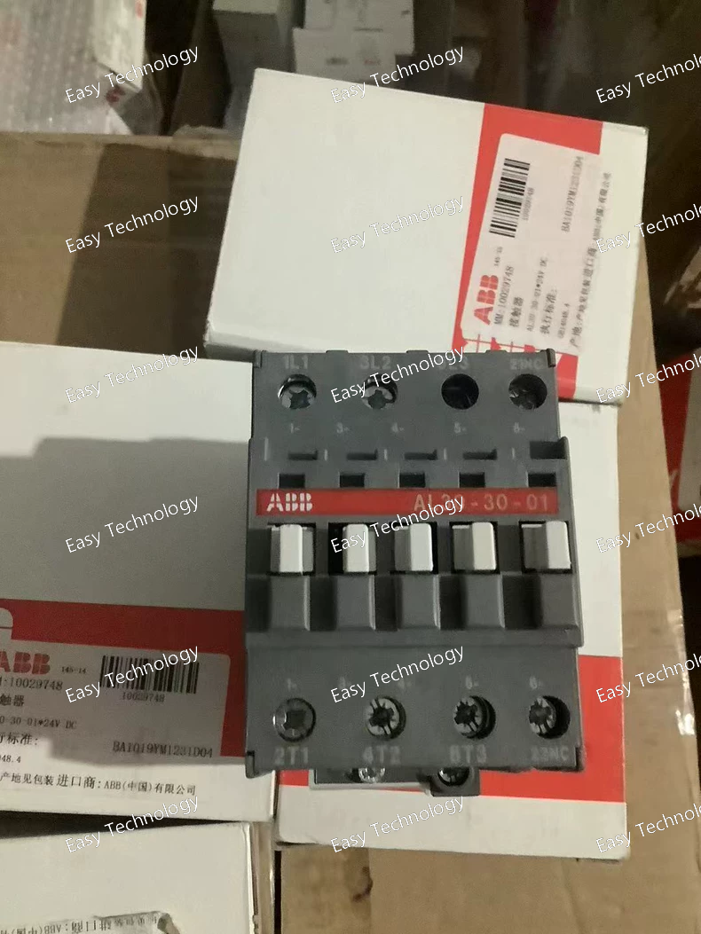
Specifications Product Type: Power Contactor Series: AL Model: AL28-30-01 (equivalent AL series designation) Rated Operational Current (Ie): 28 A (AC-3) Rated Operational Voltage (Ue): Up to 690 V AC Number of Poles: 3P Main Contact Configuration: 3 NO (Normally Open) Auxiliary Contacts: Typically 1 NO + 1 NC Control Voltage (Coil): 24 V DC Coil Type: DC operated Rated Frequency: 50 / 60 Hz Mounting Type: DIN rail or panel mounting Connection Type: Screw terminals Utilization Category: AC-3 (motor control) AC-1 (resistive loads) Typical Applications: Motor starters Industrial automation panels Pumps, fans, compressors Standards: IEC / EN 60947-4-1
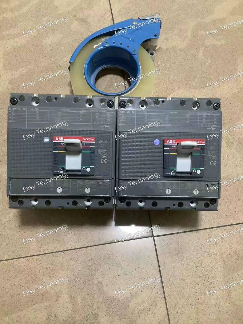
Specifications Product Type: Molded Case Circuit Breaker (MCCB) Series: Tmax XT2 Frame Size: XT2 Rated Current (In): 160 A Number of Poles: 4P Trip Unit Type: TMD (Thermal-Magnetic) Thermal Protection: Fixed setting (overload protection) Magnetic Protection: Fixed instantaneous short-circuit protection Trip Unit Setting Type: FF (Fixed Frame) Rated Operational Voltage (Ue): Up to 690 V AC Rated Frequency: 50 / 60 Hz Breaking Capacity Class: S (standard breaking capacity) Mounting Type: Fixed installation Operating Mechanism: Manual Connection Type: Screw terminals Typical Applications: Power distribution feeders Industrial and commercial electrical systems Protection of cables, transformers, and downstream equipment Standards: IEC / EN 60947-2
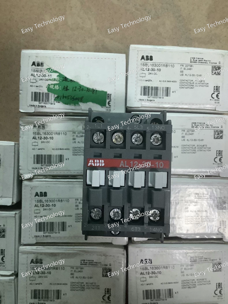
Specifications Product Type: Power Contactor Series: AL Model: AL16-30-01 (equivalent AL series designation) Rated Operational Current (Ie): 16 A (AC-3) Rated Operational Voltage (Ue): Up to 690 V AC Number of Poles: 3P Main Contact Configuration: 3 NO (Normally Open) Auxiliary Contacts: Typically 1 NO + 1 NC Control Voltage (Coil): 24 V DC Coil Type: DC operated Rated Frequency: 50 / 60 Hz Mounting Type: DIN rail or panel mounting Connection Type: Screw terminals Utilization Category: AC-3 (motor control) AC-1 (resistive loads) Typical Applications: Motor starters Industrial automation panels Pumps, fans, compressors Standards: IEC / EN 60947-4-1
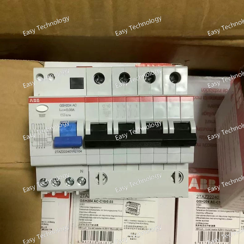
Specifications Product Type: Residual Current Circuit Breaker with Overcurrent Protection (RCBO) Series / Model: GSH204 Rated Current (In): 10 A Rated Residual Operating Current (IΔn): 30 mA Trip Type / Characteristic: C-type (instantaneous short-circuit response) Poles: 2P (Single-phase + Neutral) Rated Operational Voltage (Ue): 230 V AC Rated Frequency: 50 / 60 Hz Rated Short-Circuit Breaking Capacity (Icn / Ics): Typically 6 kA Mounting Type: DIN rail Connection Type: Screw terminals Typical Applications: Protection of circuits in residential and commercial installations Protection against earth leakage and overcurrent Lighting, socket outlets, and small appliances Standards: IEC / EN 61009-1
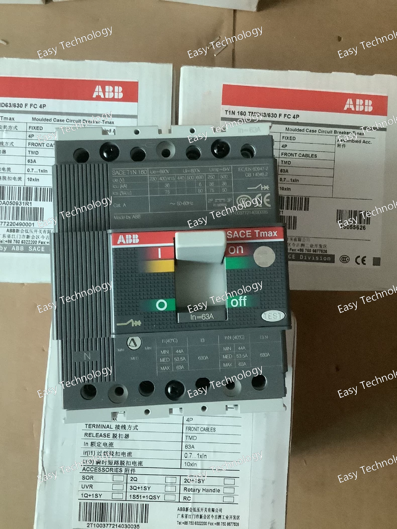
Specifications Product Type: Molded Case Circuit Breaker (MCCB) Series: T1N Frame Size: T1N160 Rated Current (In): 160 A Trip Unit Type: TMD (Thermal-Magnetic) Thermal Protection: Fixed setting (overload protection) Magnetic Protection: Fixed instantaneous short-circuit protection Magnetic Trip Range: 63 – 630 A Trip Unit Setting: FFC (Fixed Thermal / Fixed Magnetic) Number of Poles: 4P Rated Operational Voltage (Ue): Up to 690 V AC Rated Frequency: 50 / 60 Hz Mounting Type: Fixed installation Operating Mechanism: Manual Typical Applications: Power distribution feeders Industrial and commercial electrical systems Protection of cables, transformers, and downstream equipment Standards: IEC / EN 60947-2
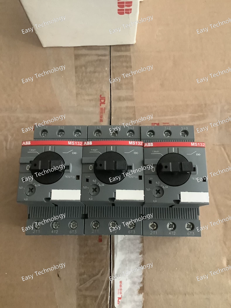
Specifications Product Type: Manual Motor Starter (MMS) Series: MS132 Rated Operational Current (Adjustable): 0.25 – 0.40 A Protection Functions: Thermal overload protection (adjustable) Magnetic short-circuit protection Phase loss sensitive Tripping Class: Class 10 Rated Operational Voltage (Ue): Up to 690 V AC Rated Insulation Voltage (Ui): 690 V Rated Frequency: 50 / 60 Hz Number of Poles: 3P Control Type: Manual ON/OFF via rotary handle Mounting Type: DIN rail or panel mounting Connection Type: Screw terminals Reset Type: Manual reset Typical Applications: Small motor protection Industrial control panels Pumps, fans, and auxiliary drives Standards: IEC / EN 60947-2, IEC / EN 60947-4-1
Specifications Product Type: Manual Motor Starter (MMS) Series: MS132 Rated Operational Current (Adjustable): 0.10 – 0.16 A Protection Functions: Thermal overload protection (adjustable) Magnetic short-circuit protection Phase loss sensitive Tripping Class: Class 10 Rated Operational Voltage (Ue): Up to 690 V AC Rated Insulation Voltage (Ui): 690 V Rated Frequency: 50 / 60 Hz Number of Poles: 3P Control Type: Manual ON/OFF with rotary handle Mounting Type: DIN rail or panel mounting Connection Type: Screw terminals Reset Type: Manual reset Typical Applications: Small motor protection Industrial control panels Pumps, fans, and auxiliary drives Standards: IEC / EN 60947-2, IEC / EN 60947-4-1
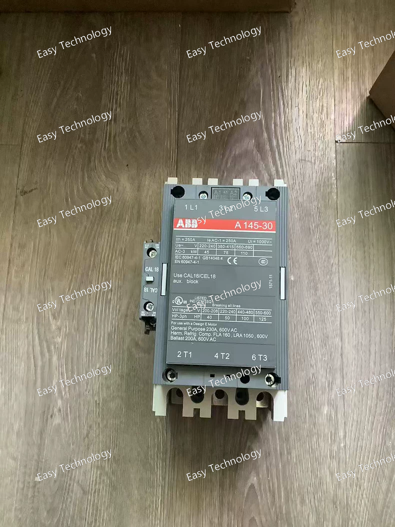
Specifications Product Type: Power Contactor Series: A Model: A145-30-11 Rated Operational Current (Ie): 145 A (AC-3) Rated Operational Voltage (Ue): Up to 690 V AC Number of Poles: 3P (main contacts) Main Contact Configuration: 3 NO Auxiliary Contacts: 1 NO + 1 NC (11) Control Voltage (Coil): 220 V AC Control Voltage Frequency: 50 / 60 Hz Utilization Category: AC-3 (motor control) AC-1 (resistive loads) Mounting Type: Panel mounting Connection Type: Screw terminals Typical Applications: Motor starters Pumps, fans, compressors Industrial automation and power distribution Standards: IEC / EN 60947-4-1
 TEL: Grace +86 13600179521
  Mail: info@hongkongeasy.com jilineasyyi@outlook.com
 Q Q:615739355
 ADDRESS:Unit 12, 20th Floor, Good View Commercial Centre, 2-16 Garden Street, Mong Kok, Hong Kong
 whats app


