
Industrial Controller
All product are in stock,guaranteed delivery within 3-7 days.


PRODUCT
PICTURE
BRAND
DESCRIBE
STOCK
DOWNLOAD
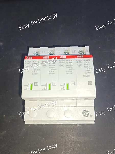
Key Technical Parameters Electrical Characteristics Surge Protection Class: Type 2 (IEC 61643‑11) Configuration: 3 phase + Neutral (3N) Nominal System AC Voltage: 400 V / 690 V AC Maximum Continuous Operating Voltage (Uc): L–PE: 440 V L–L: ~760 V L–N: 440 V N–PE: 440 V Nominal Discharge Current (8/20 µs): 20 kA Maximum Discharge Current (8/20 µs): 40 kA Impulse Current (10/350 µs): ~2 kA Voltage Protection Level (Up): L–N: ~1.8 kV N–PE: ~1.4 kV Short Circuit Withstand (Icc): 100 kA Mechanical / Functional Features Auxiliary Contact (“TS”): Potential-free NO/NC contact for remote monitoring Status Indicator: Visual indication of operation or failure Mounting: DIN rail IP Rating: IP20 Operating Temperature: −40 °C to +80 °C Modular Width: 4 modules Standards / Compliance IEC 61643‑11 (EN 61643‑11) Usage / Application Protects electrical systems against transient overvoltages in 3-phase networks (TN‑S, TT) Suitable for main distribution boards and subpanels in commercial and industrial installations TS auxiliary contact allows integration with remote alarm or building management systems
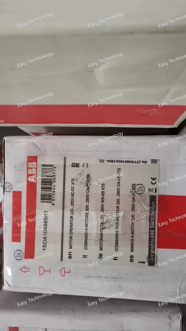
Key Specifications General Manufacturer: ABB Model / Part Number: 1SDA104885R1 (MOE XT5 220–250 V AC/DC) Product Type: Motor Operator / Motorized Circuit Breaker Actuator Series Compatibility: SACE Tmax XT series (XT5 family) Function: Provides motorized operation to open/close a compatible circuit breaker with automatic reset Control / Drive Voltage Rated Control Supply Voltage (Us): 220–250 V AC (50/60 Hz) or 220–250 V DC Drive Type: Electric motor drive for circuit breaker operation Auto‑Reset: Yes Physical / Mechanical Accessory Type: Motor operator for molded case breaker Weight: ~1.357 kg Mounting / Use: Integrated with XT5 frame breakers in distribution or control panels Approvals Standards: IEC certified, UL listed for use with suitable circuit breakers
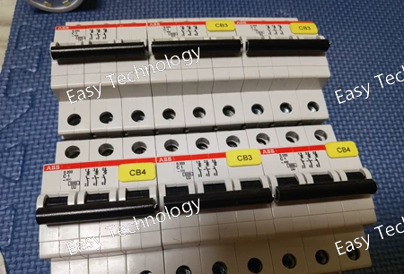
Key Specifications General Manufacturer: ABB Model / Part Number: S203‑C1 Product Type: 3‑pole miniature circuit breaker (MCB) Series: S200 series Trip Curve: C‑characteristic (general purpose) Poles: 3 poles (3P) Rated Current (In): 1 A (per pole) Modular Width: 3 modules (3 × 18 mm) Electrical Ratings Rated Operational Voltage (AC): 230/400 V AC (three‑phase system) Rated Insulation Voltage (Ui): ~440 V Rated Frequency: 50–60 Hz Thermal‑Magnetic Protection: Combined thermal overload and magnetic short‑circuit trip Breaking / Interrupting Capacity: Icu (ultimate): up to ~25 kA (IEC) at 230/400 V AC Ics (service): ~7.5–12.5 kA depending on test standards Current Limiting Class: 3 (limits let‑through energy during short bursts) Mechanical & Installation Mounting: DIN rail (TH35) mountable in distribution panels Terminal Type: Screw terminals suitable for solid and ferruled conductors Actuator/Handle: Black, sealable with ON/OFF indication Mechanical Endurance: ~20,000 cycles Electrical Endurance: ~20,000 AC cycles Operating Temperature: Approx. −25 °C to +55 °C Protection & Compliance Standards: IEC/EN 60898‑1, IEC/EN 60947‑2 (MCB isolation/protection standards) UL/CSA: Compliant versions applicable to regional markets
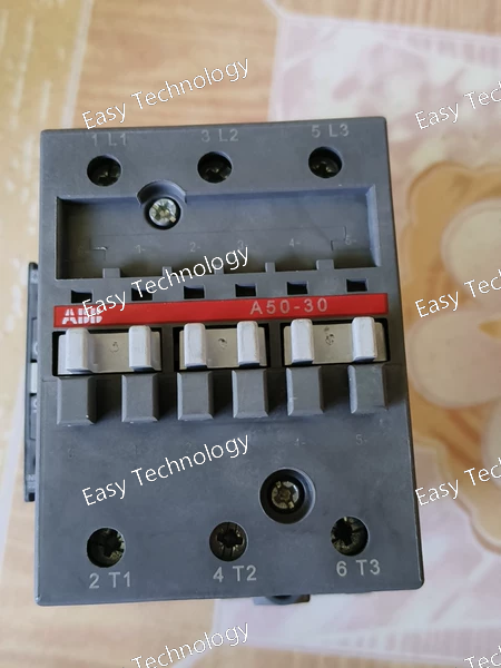
Key Specifications General / Construction Manufacturer: ABB Model / Part Number: A50‑30‑11 / 1SBL351001R8011 Product Type: 3‑Phase AC Power Contactor Series: A50 series block contactors Poles: 3 main poles (3NO) Auxiliary Contacts Built‑in: 1 Normally Open (NO) 1 Normally Closed (NC) Control Type: AC coil magnetic contactor Connection Type: Screw terminals Coil / Control Circuit Rated Control Coil Voltage (Uc): 220–230 V AC @ 50 Hz 230–240 V AC @ 60 Hz Main Circuit Ratings Rated Operational Current (AC‑3, Ie) @ 50 °C: ~50 A @ 380/400 V AC ~50–53 A @ 220–240 V AC ~45 A @ 440–500 V AC ~35 A @ 690 V AC ~23 A @ 1000 V AC Rated Operational Power (AC‑3): ~15 kW @ 220–240 V AC ~22 kW @ 380/400 V AC ~25–30 kW @ 440–500 V AC ~30 kW @ 690 V AC ~30 kW @ 1000 V AC Rated Operational Current (AC‑1, Ie): ~100 A @ 400 V AC UL/CSA General Use Rating: ~80 A @ 600 V AC Horsepower Ratings (UL/CSA): ~20 hp @ 220–240 V AC (3‑phase) ~40 hp @ 440–480 V AC (3‑phase) ~50 hp @ 550–600 V AC (3‑phase) Performance & Switching Rated Breaking Capacity (AC‑3): 8 × Ie Rated Making Capacity (AC‑3): 10 × Ie Maximum Electrical Switching Frequency: See contactor series typical industrial rates Operate / Release Times: Typical instant electromagnetic response suitable for AC control Mechanical / Environmental Impulse Withstand Voltage (Uimp): ~8 kV Mechanical Durability: Up to 10 million operations Maximum Mechanical Switching Frequency: ~3600 operations/hour Rated Insulation Voltage (Ui): ~690 V Protection Class: IP20 on enclosure/terminals Operating Temperature Range: approx. −25 °C to +60 °C (ambient) Storage Temperature Range: approx. −40 °C to +80 °C
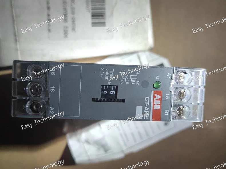
Key Specifications General Manufacturer: ABB Model / Part Number: CT‑ARE / 1SVR550127R4100 Product Type: Electronic time delay relay (OFF‑delay) Timing Function: True OFF‑delay (delay on break) Series: CT‑E timer series Mounting: DIN rail mount (TH35‑7.5 or TH35‑15) Terminal Type: Screw terminals Housing Width: ~22.5 mm Dimensions (approx): 22.5 mm (W) × 78 mm (H) × 78.5 mm (D) Weight: ~0.07 kg Operating Temperature: –20 °C to +60 °C (typical) Protection Rating: ~IP20 (front and terminals) LED Controls +1 Control / Supply Rated Control Supply Voltage (Us): 24 V AC/DC 220 – 240 V AC (50/60 Hz) The device supports multiple supply ranges so it can be used in lower voltage DC/AC circuits or mains AC control circuits. LED Controls Timing Adjustable Time Range: 0.3 s to 30 s (adjustable via front‑panel dial) Timing Function Description: When supply voltage is removed, the relay remains energized and delays switching off for the set time period. LED Controls Output Contact Configuration: 1 change‑over contact (SPDT / 1 c/o) Rated Operational Current: AC‑12: 4 A @ 230 V AC AC‑15: 3 A @ 230 V AC DC‑12: 4 A @ 24 V DC DC‑13: 2 A @ 24 V DC Contact Voltage Rating: up to 250 V AC These ratings make it suitable for controlling small contactor coils, indicator lights, and control circuits. LED Controls +1 Standards & Compliance Designed to comply with relevant IEC/EN timer relay standards (e.g., IEC/EN 61812‑1) UL 508, CAN/CSA C22.2 and other regional safety certifications RoHS compliant environmental standards
Key Specifications General Manufacturer: ABB Model / Part Number: GDA203 AC‑63/0.03 / 2TAZ812301R2630 Product Type: Residual Current Device (RCD) / Earth‑Leakage Protection Module Series: GDA200 series Poles: 3 poles (for three‑phase systems) Electrical Ratings Rated Current (In): 63 A (maximum load current carried while providing protection) Rated Residual Operating Current (IΔn): 0.03 A (30 mA) — trips when leakage ≥30 mA Type of Residual Current Detection: AC type (detects sinusoidal AC earth leakage currents) Rated Operational Voltage (Ue): ~230/400 V AC (three‑phase) Rated Insulation Voltage (Ui): ~500 V Rated Impulse Withstand Voltage (Uimp): ~4 kV Rated Frequency: 50 – 60 Hz Performance & Safety Protection Function: Detects imbalance between live conductors and trips to disconnect supply under earth‑fault conditions Safety Target: Protects against electric shock and fire risk caused by earth leakage Suitable Applications: Residential, commercial and industrial electrical distribution boards Mechanical & Environmental Number of Poles: 3 (for 3‑phase systems) Mounting: DIN‑rail mountable (standard distribution panel assembly) Operating Ambient Temperature Range: typically −25 °C to +55 °C Degree of Protection: typical IP ratings for distribution module blocks Electrical Endurance: Typical high‑cycle durability for distribution devices
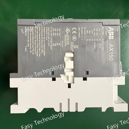
Key Specifications General Manufacturer: ABB Model / Part Number: AX150‑30‑11‑85 / 1SFL991074R8011 Product Type: 3‑Phase AC Contactor Series: AX Series Mounting: Panel or enclosure Mechanical Endurance: High industrial durability Main Circuit Number of Main Contacts: 3 Normally Open (3NO) Auxiliary Contacts: 1 Normally Open (NO) + 1 Normally Closed (NC) Rated Operational Voltage (AC‑3, Ie): ~150 A @ 380/400 V AC; ~100 A @ 440–500 V AC; ~82 A @ 690 V AC Rated Operational Power (AC‑3): ~75 kW @ 380/400 V; ~59 kW @ 440–500 V; ~75 kW @ 690 V AC Rated Breaking Capacity (AC‑3): 8 × Ie Rated Making Capacity (AC‑3): 10 × Ie Rated Operational Current (AC‑1, Ie): ~190 A @ 690 V AC Control / Coil Rated Control Voltage (Uc): 380 V AC typical Rated Frequency: 50/60 Hz Mechanical & Environmental Rated Insulation Voltage (Ui): 690 V Impulse Withstand Voltage (Uimp): 8 kV Mechanical & Electrical Durability: Long life cycle suitable for heavy-duty industrial applications Terminal Type: Heavy-duty bar terminals Operating Temperature Range: −40 °C to +70 °C (ambient, depending on installation conditions) Applications 3‑phase motor control and switching Industrial power distribution Load isolation and control in automation systems General AC power circuit control
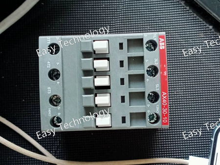
Key Specifications General / Mechanical Manufacturer: ABB Model / Part Number: AX40‑30‑10‑80 / 1SBL321074R8010 Product Type: 3‑Phase AC Power Contactor Series: AX40 (AX contactor series) Poles: 3 main poles (3NO) Auxiliary Contacts: 1 Normally Open (1NO) Main Circuit Ratings Rated Operational Voltage: Up to 690 V AC Conventional Free‑air Thermal Current (Ith): 65 A (@ 40 °C) Rated Operational Current AC‑1 (Ie): ~60 A @ 220‑240 V AC; ~60 A @ 690 V AC Rated Operational Current AC‑3 (Ie): 40 A @ 220‑240 V AC (55 °C) 40 A @ 380‑400 V AC (55 °C) 37 A @ 440 V AC 33 A @ 500 V AC 25 A @ 690 V AC Rated Operational Power (AC‑3): 11 kW @ 220‑240 V AC 18.5 kW @ 380‑400 V AC 22 kW @ 440‑500 V AC 22 kW @ 690 V AC Rated Insulation Voltage (Ui): 690 V AC Control Circuit / Coil Rated Control Circuit Voltage (Uc): 220 – 230 V AC @ 50 Hz 230 – 240 V AC @ 60 Hz
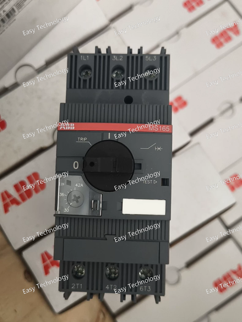
Key Specifications General Manufacturer: ABB Model / Part Number: MS165‑42 / 1SAM451000R1015 Product Type: Manual Motor Starter / Motor Protection Circuit Breaker Series: MS165 series Mounting: DIN rail (standard TH35) Electrical Ratings Rated Operational Current (Ie): 42 A Adjustable Overload Setting Range: 30 – 42 A Rated Operating Voltage: 208 – 690 V AC Rated Insulation Voltage (Ui): 1000 V Short‑Circuit Release Setting (Ii): 630 A Rated Service Short‑Circuit Breaking Capacity (Ics): 50 kA @ 230 V AC 50 kA @ 400 V AC 30 kA @ 500 V AC 10 kA @ 690 V AC Rated Ultimate Short‑Circuit Breaking Capacity (Icu): same as Ics for most voltages Rated Operational Power (AC‑3): ~22 kW @ 400 V AC Protection & Function Motor Protection: Thermal and short‑circuit protection with trip class 10 Phase Failure Sensitivity: Yes Disconnect Function: Built‑in (acts as manual disconnect) Trip‑Free Mechanism and Temperature Compensation included Handle Lockable: Yes (can be padlocked in OFF position) Mechanical & Physical Number of Poles: 3 Terminal Type: Screw terminals Degree of Protection: IP20 (housing) Mechanical Endurance: ~50,000 operations Electrical Endurance: ~25,000 operations Mounting Position: Any (DIN rail) Approx. Dimensions: ~55 mm (W) × ~142.6 mm (H) × ~122.1 mm (D) Approx. Weight: ~0.97 kg Applications Motor control and protection in industrial systems Protection of pumps, fans, compressors, conveyors Manual switching and motor overload protection
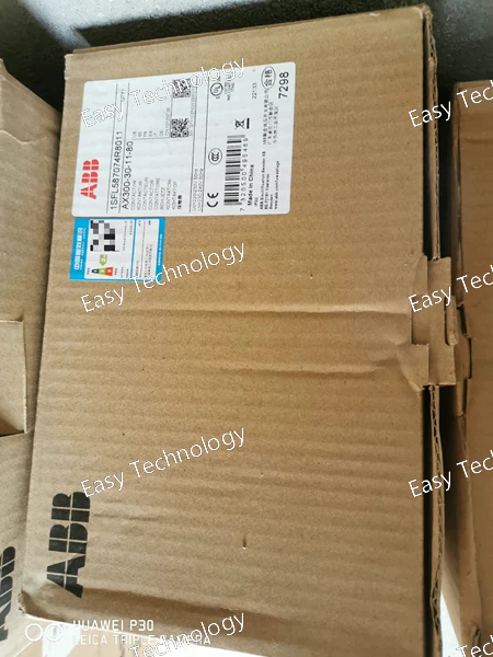
Key Specifications General / Main Circuit Manufacturer: ABB Model / Part Number: AX300‑30‑11‑80 / 1SFL587074R8011 Product Type: 3‑Phase AC Contactor (Heavy Duty) Series: AX300 Size (AX Series) Number of Main Contacts: 3 Normally Open (3NO) Auxiliary Contacts: 1 Normally Open (NO) + 1 Normally Closed (NC) Rated Operational Voltage (Main Circuit): Up to 690 V AC Rated Operational Current (AC‑3, Ie) @ 55 °C: ~305 A @ 380 400 V AC; ~290 A @ 500 V AC; ~290 A @ 690 V AC Rated Operational Power (AC‑3): ~160 kW @ 380/400 V AC ~200 kW @ 500 V AC ~250 kW @ 690 V AC ~90 kW @ 220/230/240 V AC Rated Control Circuit Voltage (Uc): ~220 … 230 V AC @ 50 Hz ~230 … 240 V AC @ 60 Hz Rated Insulation Voltage (Ui): ~690 V AC Making / Breaking: Designed for heavy switching duties with robust contact design Electrical & Mechanical Performance Rated Free‑air Thermal Current (Ith): Designed for high current applications Coil Operating Limits: 220–230 V AC @ 50 Hz; 230–240 V AC @ 60 Hz Maximum Electrical Switching Frequency: Typical industrial duty Mechanical Durability: Long life cycle suitable for industrial use Terminals: Heavy‑duty bar terminals for main circuit connections Physical / Environmental Mounting: Panel or enclosure mounting in industrial control panels Approx. Dimensions (H×W×D): ~225 mm × 140 mm × 180 mm Net Weight: ~4.7 kg Ambient Temperature Range: Typical industrial range (e.g., −40 °C to +70 °C without overload relay; −25 °C to +55 °C near thermal relay) Protection Class: Typically IP20 on auxiliary terminals and general enclosure Maximum Operating Altitude: Up to ~3000 m without derating
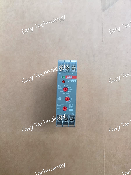
Key Specifications General Manufacturer: ABB Model / Part Number: CT‑MFE / 1SVR550029R8100 Product Type: Multifunction electronic time delay relay (timer) Timer Family: CT‑E series Mounting: DIN rail (TH35‑7.5 or TH35‑15) compatible Terminal Type: Screw terminals Weight: ~0.07 kg Dimensions (Approx): 22.5 mm (W) × 78 mm (H) × 78.5 mm (D) Control / Timing Rated Control Supply Voltage (Us): 24 – 240 V AC/DC Time Range: 0.05 s up to 100 h Timing Functions (Multifunction): ON‑Delay OFF‑Delay Impulse ON Flasher (starting with ON) Flasher (starting with OFF) Pulse Former Output Contact Configuration: 1 change‑over (SPDT / 1 c/o) output contact Rated Operational Current (AC‑12): 4 A @ 230 V Rated Operational Current (AC‑15): 3 A @ 230 V Rated Operational Current (DC‑12): 4 A @ 24 V Rated Operational Current (DC‑13): 2 A @ 24 V Contact Rating: Up to ~250 V AC, 4 A Standards & Compliance Complies with IEC/EN 61812‑1 timing relay standards Meets CAN/CSA C22.2 No. 14, UL 508 and related safety standards RoHS compliant
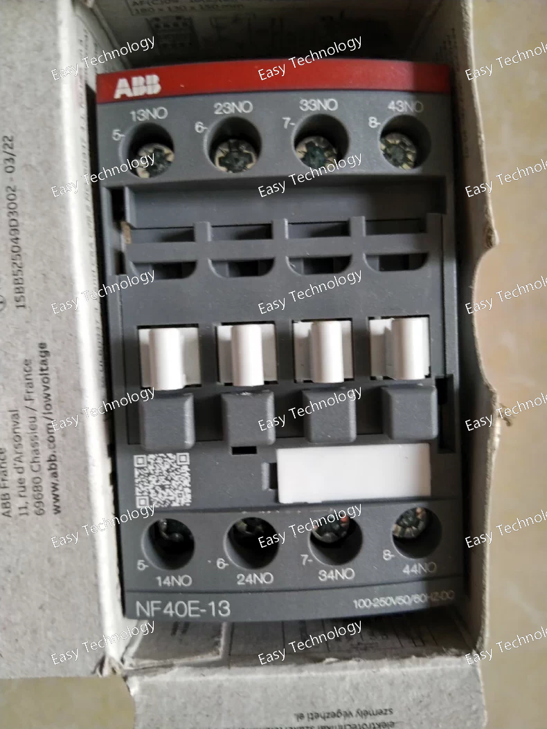
Key Specifications General / Mechanical Model / Part Number: AF26‑30‑00‑13 / 1SBL237001R1300 Product Type: 3‑Pole Power Contactor Series: AF Contactors Number of Main Contacts: 3 Normally Open (3 NO) Connection Type: Screw terminals Design: Block‑type compact contactor Dimensions (approx): 45 mm (W) × 86 mm (H) × 86 mm (D) Weight (approx): 0.31 kg Protection Class: IP20 enclosure for terminals and contactor body Mechanical Endurance: ~10 million operations Operating Temperature: Without thermal overload relay −40 °C to +70 °C; with overload relay −25 °C to +60 °C Storage Temperature: −60 °C to +80 °C Altitude: Up to 3000 m without derating Impulse Withstand Voltage: 6 kV Rated Insulation Voltage (Ui): 690 V (IEC) / 600 V (UL/CSA) Standards Compliance: IEC/EN 60947‑1, IEC/EN 60947‑4‑1, UL/CSA C22.2 Control / Coil Rated Control Circuit Voltage (Uc): 100–250 V AC or DC, 50/60 Hz Control Voltage Range: Suitable for both AC and DC operation without coil changes Main Circuit / Electrical Ratings Rated Operational Voltage (Main Circuit): Up to 690 V AC (IEC) / 600 V AC (UL/CSA) Rated Operational Current (AC‑1, Ie): 45 A @ 690 V AC (40 °C) Rated Motor Control (AC‑3, Ie): 26 A @ 400 V AC for 3‑phase motors Rated Operational Power (AC‑3): ~6.5 kW @ 230–240 V; ~11 kW @ 380–415 V; ~15 kW @ 440–500 V / 690 V AC depending on load Maximum Breaking Capacity: ~200 A at 690 V AC; ~500 A at 440 V AC Rated Power (NEMA/UL): 15 hp @ 480 V AC; 20 hp @ 550–600 V AC Operating Times: Typical operate and release times ~10–100 ms Performance Switching Frequency: Suitable for typical industrial switching tasks Suitable Loads: Motors, resistive and slightly inductive loads, general power circuits Auxiliary Contacts: Optional add‑on auxiliary contacts can be mounted for control circuits
 TEL: Grace +86 13600179521
  Mail: info@hongkongeasy.com jilineasyyi@outlook.com
 Q Q:615739355
 ADDRESS:Unit 12, 20th Floor, Good View Commercial Centre, 2-16 Garden Street, Mong Kok, Hong Kong
 whats app


